
Month: April 2021
Capacitive Touch
const int touchPin = 2;

void setup() {
  Serial.begin(9600);
  pinMode(3, OUTPUT);
}

void loop() {
  int capacitance = readCapacitivePin(touchPin);
  Serial.println(capacitance);
  if (capacitance > 3)
    digitalWrite(3, HIGH);
  else
    digitalWrite(3, LOW);
}


// readCapacitivePin
//  Input: Arduino pin number
//  Output: A number, from 0 to 17 expressing
//  how much capacitance is on the pin
//  When you touch the pin, or whatever you have
//  attached to it, the number will get higher
#include "pins_arduino.h" // Arduino pre-1.0 needs this
uint8_t readCapacitivePin(int pinToMeasure) {
  // Variables used to translate from Arduino to AVR pin naming
  volatile uint8_t* port;
  volatile uint8_t* ddr;
  volatile uint8_t* pin;
  // Here we translate the input pin number from
  //  Arduino pin number to the AVR PORT, PIN, DDR,
  //  and which bit of those registers we care about.
  byte bitmask;
  port = portOutputRegister(digitalPinToPort(pinToMeasure));
  ddr = portModeRegister(digitalPinToPort(pinToMeasure));
  bitmask = digitalPinToBitMask(pinToMeasure);
  pin = portInputRegister(digitalPinToPort(pinToMeasure));
  // Discharge the pin first by setting it low and output
  *port &= ~(bitmask);
  *ddr  |= bitmask;
  delay(1);
  uint8_t SREG_old = SREG; //back up the AVR Status Register
  // Prevent the timer IRQ from disturbing our measurement
  noInterrupts();
  // Make the pin an input with the internal pull-up on
  *ddr &= ~(bitmask);
  *port |= bitmask;

  // Now see how long the pin to get pulled up. This manual unrolling of the loop
  // decreases the number of hardware cycles between each read of the pin,
  // thus increasing sensitivity.
  uint8_t cycles = 17;
  if (*pin & bitmask) {
    cycles =  0;
  }
  else if (*pin & bitmask) {
    cycles =  1;
  }
  else if (*pin & bitmask) {
    cycles =  2;
  }
  else if (*pin & bitmask) {
    cycles =  3;
  }
  else if (*pin & bitmask) {
    cycles =  4;
  }
  else if (*pin & bitmask) {
    cycles =  5;
  }
  else if (*pin & bitmask) {
    cycles =  6;
  }
  else if (*pin & bitmask) {
    cycles =  7;
  }
  else if (*pin & bitmask) {
    cycles =  8;
  }
  else if (*pin & bitmask) {
    cycles =  9;
  }
  else if (*pin & bitmask) {
    cycles = 10;
  }
  else if (*pin & bitmask) {
    cycles = 11;
  }
  else if (*pin & bitmask) {
    cycles = 12;
  }
  else if (*pin & bitmask) {
    cycles = 13;
  }
  else if (*pin & bitmask) {
    cycles = 14;
  }
  else if (*pin & bitmask) {
    cycles = 15;
  }
  else if (*pin & bitmask) {
    cycles = 16;
  }

  // End of timing-critical section; turn interrupts back on if they were on before, or leave them off if they were off before
  SREG = SREG_old;

  // Discharge the pin again by setting it low and output
  //  It's important to leave the pins low if you want to
  //  be able to touch more than 1 sensor at a time - if
  //  the sensor is left pulled high, when you touch
  //  two sensors, your body will transfer the charge between
  //  sensors.
  *port &= ~(bitmask);
  *ddr  |= bitmask;

  return cycles;
}
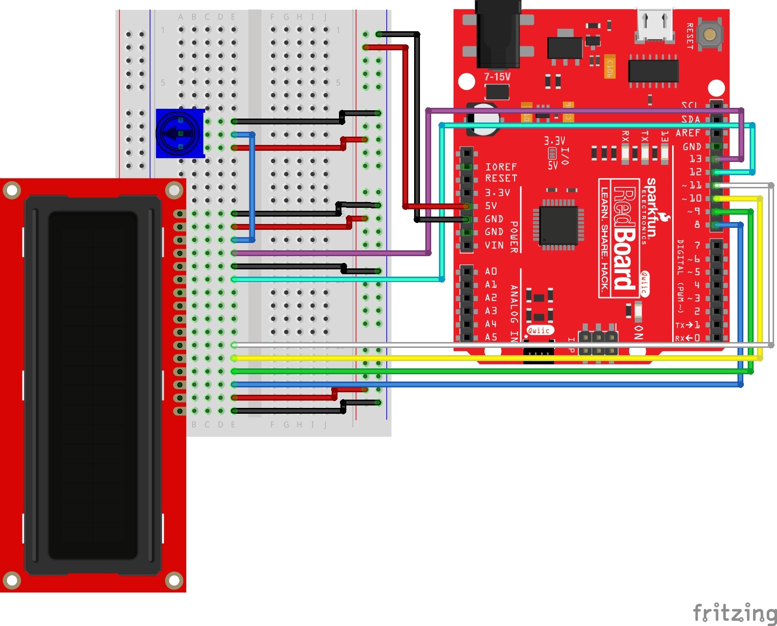
Arduino LCD Screen
This is from the Sparkfun tutorials online found here. More code examples available here.
/*
  SparkFun Inventor’s Kit
  Circuit 4A-HelloWorld

  The LCD will display the words "Hello World" and show how many seconds have passed since
  the RedBoard was last reset.

  This sketch was written by SparkFun Electronics, with lots of help from the Arduino community.
  This code is completely free for any use.

  View circuit diagram and instructions at: https://learn.sparkfun.com/tutorials/sparkfun-inventors-kit-experiment-guide---v41
  Download drawings and code at: https://github.com/sparkfun/SIK-Guide-Code
*/

#include <LiquidCrystal.h>          //the liquid crystal library contains commands for printing to the display

LiquidCrystal lcd(13, 12, 11, 10, 9, 8);   // tell the RedBoard what pins are connected to the display

void setup() {

  lcd.begin(16, 2);                 //tell the lcd library that we are using a display that is 16 characters wide and 2 characters high
  lcd.clear();                      //clear the display
}

void loop() {

  lcd.setCursor(0, 0);              //set the cursor to the 0,0 position (top left corner)
  lcd.print("Hello, world!");       //print hello, world! starting at that position

  lcd.setCursor(0, 1);              //move the cursor to the first space of the bottom row
  lcd.print(millis() / 1000);       //print the number of seconds that have passed since the last reset
}
Final project description/progress
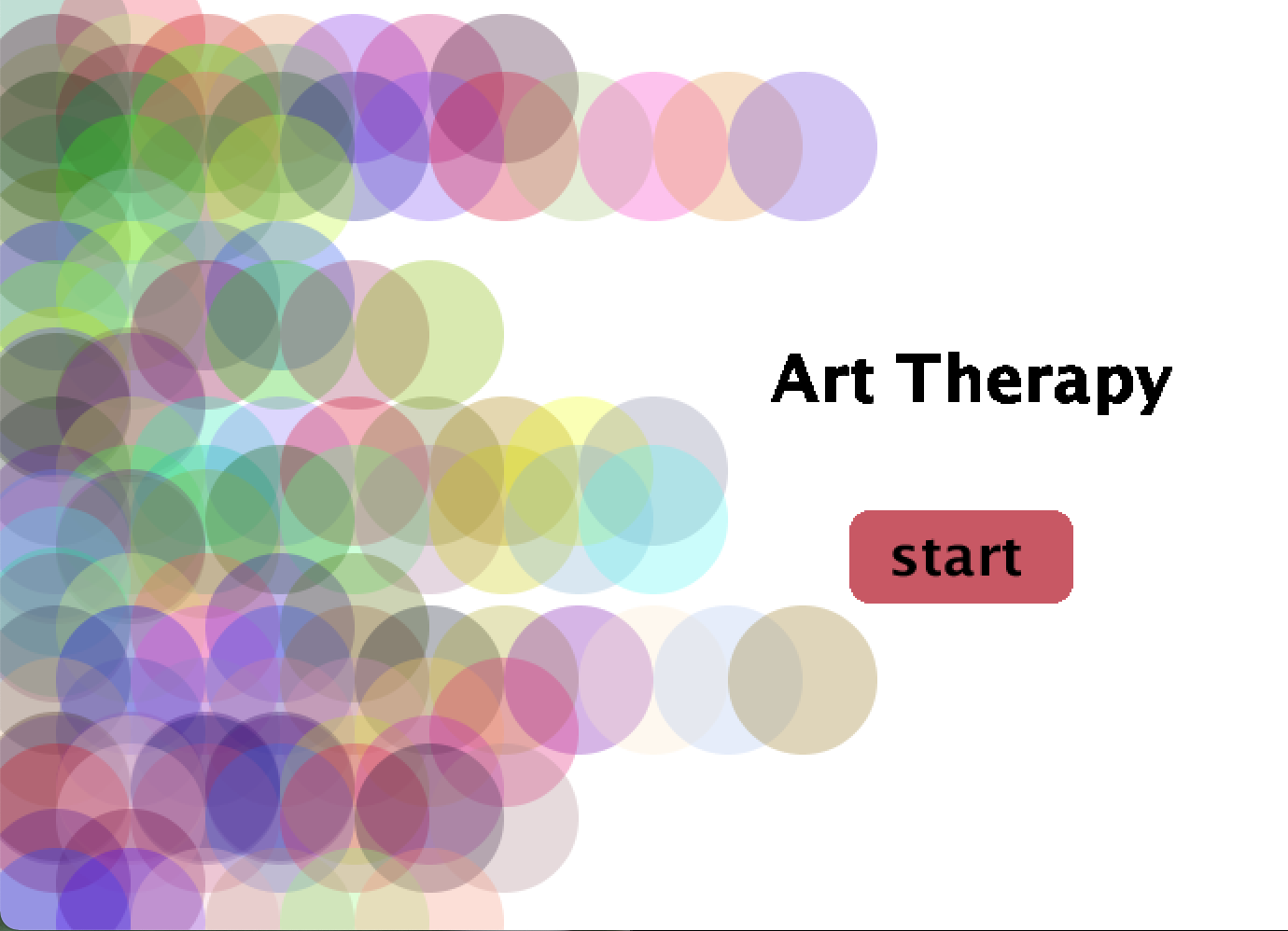
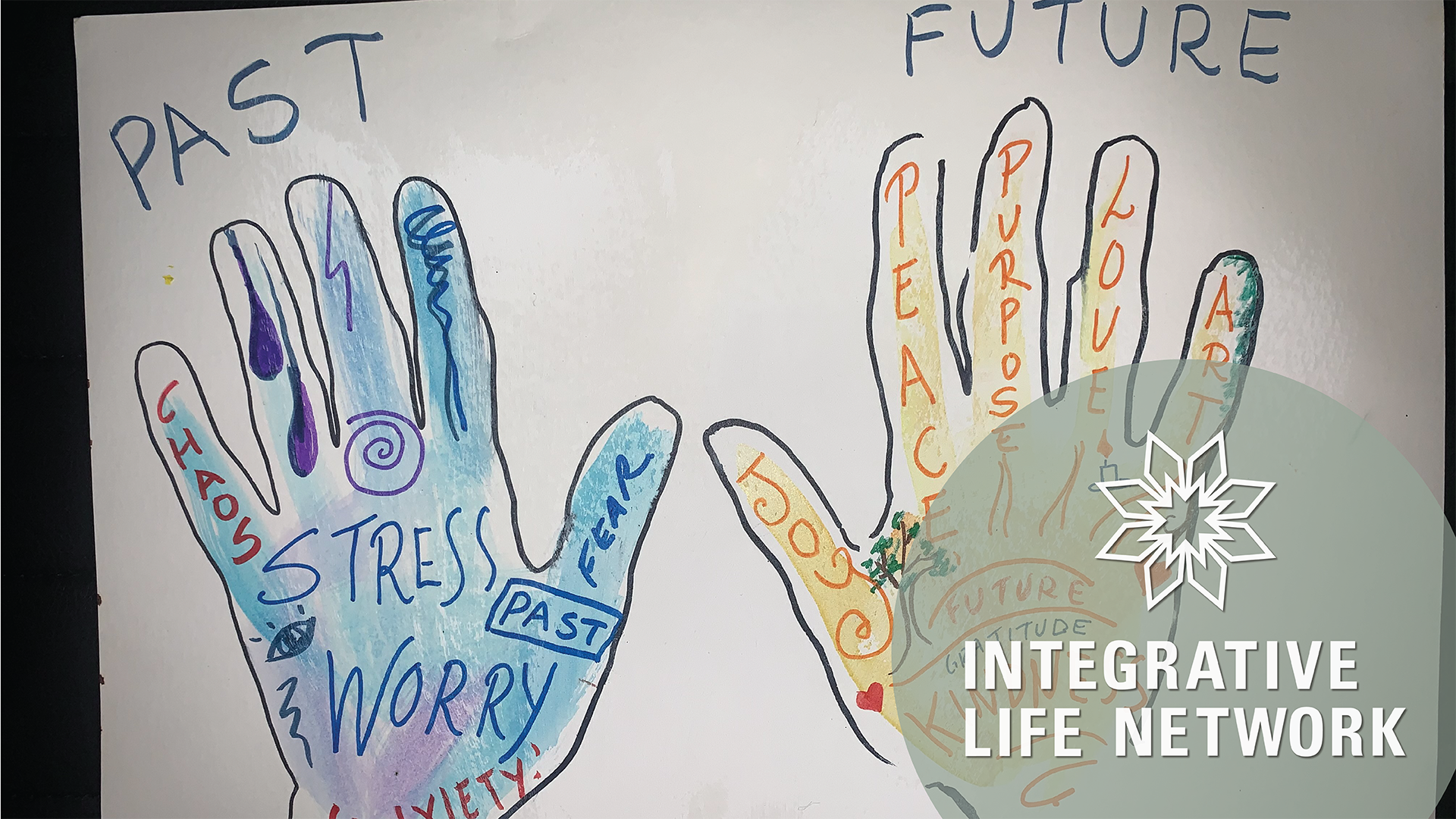
So, i decided to choose one idea for my final and started a big research. As I a little bit tired of the games and musical instruments, i want to work on generative art. I’m gonna create an art application with different modes for different users. This topic also coincides with mental health and social studies.
I found some readings about effectiveness of art therapy and results after it
Artistic resources:
In a process of creating a main screen (not final version)
Final Project Progress – Thais And Armaan
Updated Project Idea:
Our project idea has been modified a bit now and is about creating a driving experience for the user in which the user chooses a circuit in processing and uses a joystick to drive a car (made using arduino) and attempts to finish the circuit shown on their processing screens.
For this week, we managed to figure out how to make the core of our project work. We found out a way to use a joystick as an input and then send that information to processing which then communicates it to the Arduino causing a change in it which we can then use as an output. This was actually so time consuming and we had to wrap our brains around how we could make this possible but eventually we found a library on processing called Game Control Plus and G4P which allowed us to configure processing so that we can design what each button in our joystick would do and this would be stored as a separate library which we could then import into our main processing code and use within it.
Meanwhile, we also started working on our processing interface and set up the following game screens:
menu()
- Contains the main menu for the game in which the player can choose to play the game or read the instructions or change settings
choose_circuit()
- The playable component of the game wherein the player chooses the circuit they want to race their car in
instruction()
- Details game instructions
setting()
- To change game settings
gameover()
- To signify end of game
Code
The following is the code that we have written till now:
For the Joystick:
int ledPin = 4;

float brightness = 0;

void setup() {
  Serial.begin(9600);
  Serial.println("0");
  pinMode(ledPin, OUTPUT);
}

void loop() {
  while (Serial.available()) {
    //get the brightness value from processing
    brightness = Serial.parseFloat();

    if (Serial.read() == '\n') {
    //turn on the LED with the given brightness
      analogWrite(ledPin, brightness);
      Serial.println(brightness);
    }
  }
}
Arduino code to test out the effect of a joystick on an LED light and toggle it on or off
import net.java.games.input.*;
import org.gamecontrolplus.*;
import org.gamecontrolplus.gui.*;

import processing.serial.*;

Serial myPort;

ControlDevice cont;
ControlIO control;

float press;

void setup()
{


  size(360, 200);
  control = ControlIO.getInstance(this);
  cont = control.getMatchedDevice("LED_Input");

  if (cont == null)
  {
    println("not today champ");
    System.exit(-1);
  }


   printArray(Serial.list());
  String portname=Serial.list()[0];
  println(portname);
  myPort = new Serial(this, portname, 9600);
  myPort.clear();
  myPort.bufferUntil('\n');
}

void draw()
{
  background(press);
  getInput();
}

public void getInput()
{
  press = map(cont.getSlider("analog").getValue(), -1, 1, 0, 255);
  println(press);
}


void serialEvent(Serial myPort) {
  String s=myPort.readStringUntil('\n');
  s=trim(s);

  //write brightness so that Arduino can use it
  myPort.write(press + "\n");
}
We also created a library called “LED_Input” using the GCP Configurator Example of the GCP Library
Housekeeping
- We set up a notion page to better manage our work flow
- https://www.notion.so/Final-Notes-b013a1ba19a4439a9d9836da5b183881
- We sit up a github repo to better manage our coding work flow.
- https://github.com/Armaan-Agrawal/Intro_To_IM_Final
Finally, here is a short video showing the joystick and its interaction with arduino…. and also our excitement :))
Final Project Progress
For my project, I’m building some sort of contraption to accompany Zoom classes. It’s been a chaotic week and I haven’t made as much progress as I would have liked, but I’ve been playing around with the speech recognition library in P5.js.
Here’s my code thus far:
	var myRec = new p5.SpeechRec('en-US', parseResult); // new P5.SpeechRec object
	myRec.continuous = true; // do continuous recognition
	myRec.interimResults = true; // allow partial recognition (faster, less accurate)
var recordedString = "";

	var x, y;
	var dx, dy;

	function setup()
	{
		// graphics stuff:
		createCanvas(800, 600);
		background(255, 255, 255);
		fill(0, 0, 0, 255);


		// instructions:
		textSize(20);
		textAlign(LEFT);


		//myRec.onResult = parseResult; // now in the constructor
		myRec.start(); // start engine
	}

	function draw()
	{
		text(recordedString, 20,20);
	}

	function parseResult()
	{
			var mostrecentword = myRec.resultString.split(' ').pop();
			recordedString += mostrecentword;

	}
I still need to add the functionality for wrapping the string and making sure that it removes a word printed if it realizes it’s actually a different word. For instance, when saying the word “happening’, “happy” would print to the screen and then “happening.”
This week, I hope to get started on building a capacitor sensor (foil inside pillow).
Week 13 Final Project Progress
Summary:
For this week, I decided to work on planning for my project and organizing my thoughts to see if my project was achievable. Honestly, I did not. had much time this week to start the coding part of my project so I decided to think about what different things I should implement.
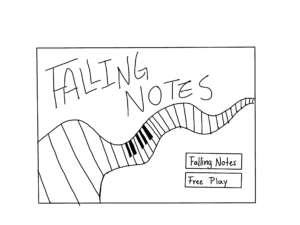
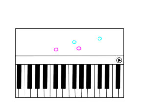
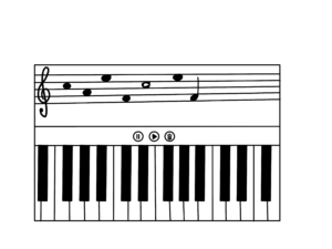
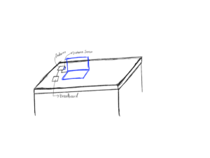
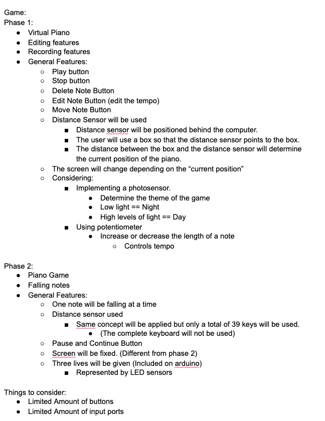
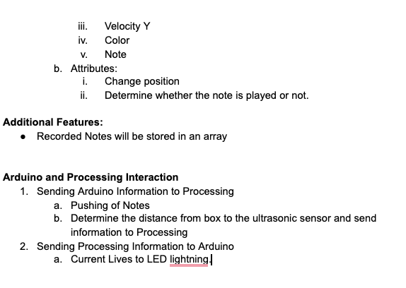
Game:
My game mainly consists of two parts. The first part will be a free piano play where the user can record, edit, delete, move notes to compose a musical piece. The second part of the game is an actual game where notes will be falling above piano tiles and the user must push the button representing the tile. For this game, I had decided to only implement buttons and the potentiometer to control the position of the piano. However, after Prof. Aaron’s suggestion about making it more interactive, I decided to implement additional features. I will be using the ultrasonic sensor and a box to represent the position of the user in the piano instead of the potentiometer. I will also use additional features such as the photosensor, LED lights, and buttons.
Progress for this week.
For this week basically, I created sketches of what my goal for my final project is. I created sketches for the basic look of the game for both phase 1 and phase 2. I also organized my thoughts and wrote down what I thought was necessary for the game. I created a document where I wrote about what different classes were needed to create this project. I also created a brief sketch of what my initial screen should look like.
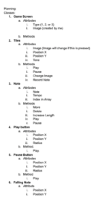
Conclusion and Reflection:
Honestly, this week I could not accomplish much on my project. I am proud that I organized my thoughts and started thinking about how Arduino and Processing should interact as well as planning what the general game should look like. I am not satisfied with this week’s progress and therefore I plan on working much more this week. For this week, my plan is to accomplish the first phase of the game and have good progress on the second part so that I can work on the aesthetic part of the game next week.
Progress in Final Project
PROGRESS
Once I’m more or less decided on my project, I went to do my little research on the many possibilities that Processing tool has to offer. I found many libraries and examples implemented in Processing, such as Mirror by Daniel Shiffman which quite literally shows ur reflection captured by webcam, or PeasyCam that transforms ur face and shows in three-dimensional space.
CHALLENGES:
I have faced an issue related to the Capture function, the camera is denying access to processing to run the program and open the webcam.
BaseSrc: [avfvideosrc0] : Device video access permission has just been denied
Could not run the sketch
(Target VM failed to initialize).
Professor later explained that this has to do with the privacy and security settings of new macOS not letting processing open the camera due to strict security restrictions.
CODE:
// daniel shiffman's library on mirror
import processing.video.*;
// Size of each cell in the grid
int cellSize = 20;
// Number of columns and rows in our system
int cols, rows;
// Variable for capture device
Capture video;


void setup() {
  size(640, 480);
  frameRate(30);
  cols = width / cellSize;
  rows = height / cellSize;
  colorMode(RGB, 255, 255, 255, 100);

  // This the default video input, see the GettingStartedCapture
  // example if it creates an error
  video = new Capture(this, width, height);

  // Start capturing the images from the camera
  video.start();

  background(0);
}


void draw() {
  if (video.available()) {
    video.read();
    video.loadPixels();

    // Begin loop for columns
    for (int i = 0; i < cols; i++) {
      // Begin loop for rows
      for (int j = 0; j < rows; j++) {

        // Where are we, pixel-wise?
        int x = i*cellSize;
        int y = j*cellSize;
        int loc = (video.width - x - 1) + y*video.width; // Reversing x to mirror the image

        float r = red(video.pixels[loc]);
        float g = green(video.pixels[loc]);
        float b = blue(video.pixels[loc]);
        // Make a new color with an alpha component
        color c = color(r, g, b, 75);

        // Code for drawing a single rect
        // Using translate in order for rotation to work properly
        pushMatrix();
        translate(x+cellSize/2, y+cellSize/2);
        // Rotation formula based on brightness
        rotate((2 * PI * brightness(c) / 255.0));
        rectMode(CENTER);
        fill(c);
        /noStroke();
        // Rects are larger than the cell for some overlap
        ellipse(0, 0, 1, random (20,100));
        popMatrix();
      }
    }
  }
}
VIDEO
Final Project Progress – by Cole and Shreya
Please read through my previous blog post if you haven’t to better follow this one 🙂
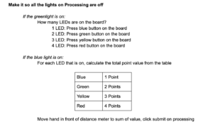
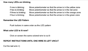
Once Cole and I had finalized our idea for the final project, the first very important thing was to finalize the instructions for bomb diffusion. We both had a preliminary idea on how our game should work – have LEDs light up to give a signal, press buttons according to that, this should give you the next task to do and a few such tasks should culminate in cutting a wire. This seemed very easy until we started making a plan. We realized, there were a lot of things to consider, and based on that, we could have many permutations of things we could do / signals and tasks we could create. So we decided on the things we will be using on our Arduino board for input and output first. Due to limited pins, we had to maximize what we could use and different signals we could create. We decided on 4 LEDs as output signals and 4 buttons (different colors), potentiometer, and distance meters as inputs. We made a complete plan on how to start, which instruction will lead to what and so. It can be found below. And I must mention, it took longer than we thought and harder than we assumed to chart this plan!
After this plan was made, Cole and I decided to first get started with some basics of our Arduino and interface on Processing.
Interface of Processing
We decided to start with the interface first because once we have the visualization, it will be easy to display the Arduino reads on the screen and check if our code/wiring is appropriate or not. Also, it is very hard to code the entire logic with no visible output. So, once we integrate Arduino with processing, we should be able to see the results on the screen.
I started with sketching the wires. I was thinking about how it could be possible to have wires disappear once they are cut. The best way I could imagine was draw these pieces individually and then display the appropriate wires based on their state (1 for uncut and 0 for uncut).
Next, I wanted to try to make the distance meter and potentiometer reading on screen. For testing purposes, I made them map to mouseX. This will be switched to Arduino readings later. The rotation of the needle was a little hard to achieve because I wanted it to pivot over a very particular point in the image. With a little trial and error and some calculations, I think I got that right!
You can find the working videos below:
I am currently working on displaying the bomb timer/countdown on the screen. This is proving to be a bit challenging. After this, I will start with the driver program for the game which is the LED sequences, and randomizing those. Based on that, the code for the rest of the game will follow. Each LED sequence needs to wait for input and update multiple flag variables and then change the sequence to give the next signal. I have charted out a plan on how this will work… implementation will hopefully follow soon 🙂
Arduino Part
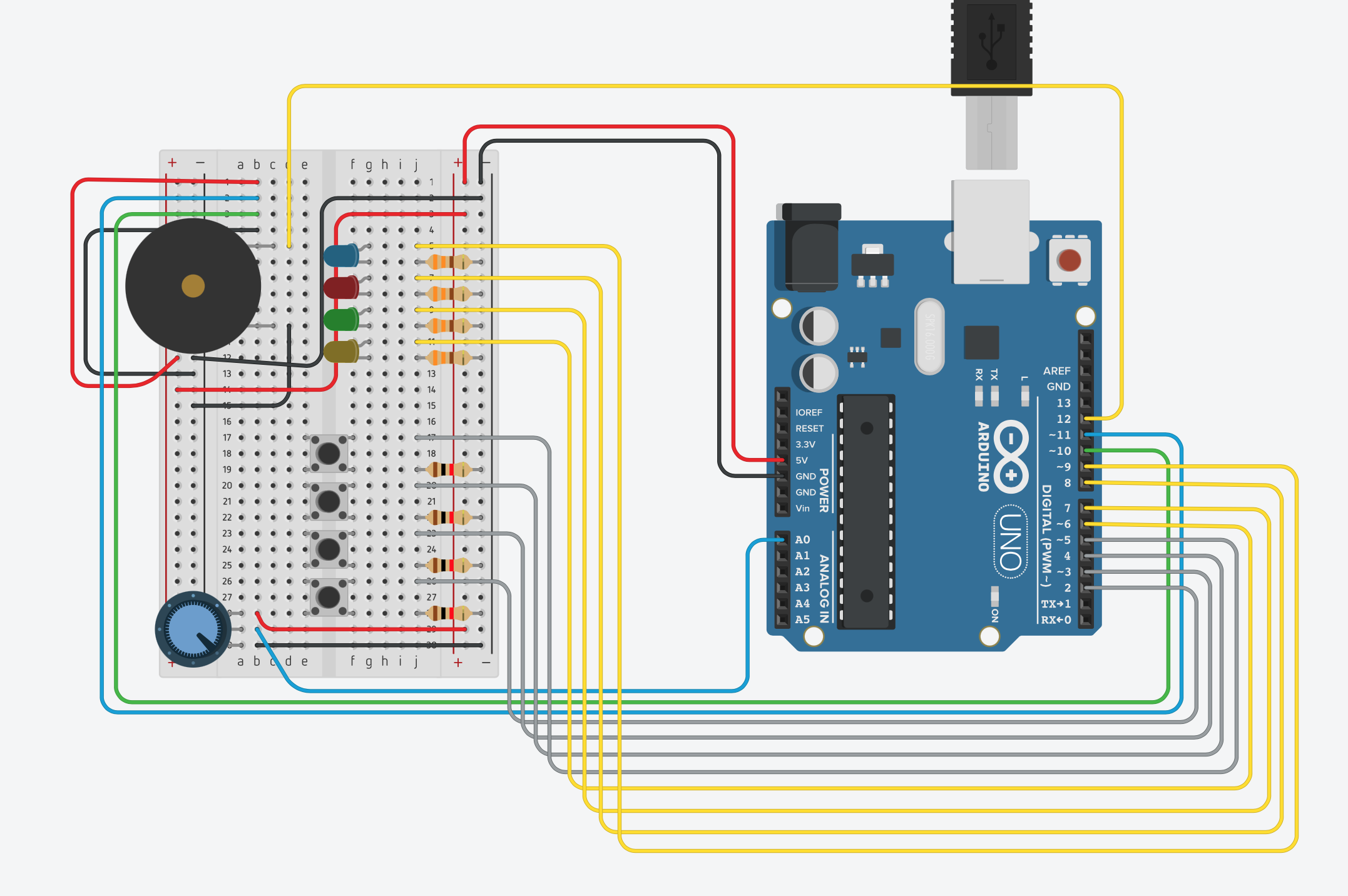
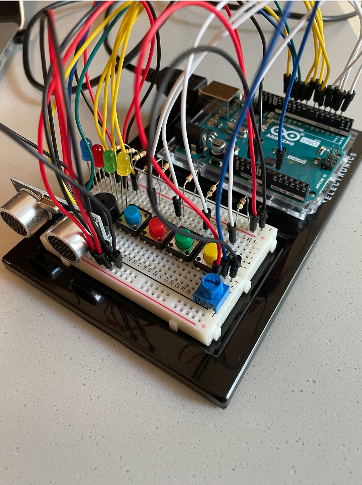
For the Arduino part, Cole finished creating the Arduino with all the wiring. On the board, we have 4 LEDs, 4 buttons with corresponding colors to the LEDs, a potentiometer, a distance sensor, and a buzzer.
We have also completed the Arduino code needed to control the whole board from Processing as well as send the inputs from the sensors back.
Here is the Arduino circuit (note the distance meter in Tinkercad is a 3 pin, not a 4 pin variant like we have so I just placed 4 wires in the top left corner where the distance meter is actually at)
Code
For the above, I have started with creating a few classes (currently have one for the wires, more are to come for the timer and LEDs). I have also broken down the into various sections and made functions based on different game stages / input we are waiting for from the bomb diffuser.
The Arduino code has also been completed by Cole as mentioned above.
For the full code (Arduino and Processing), you can follow this GitHub link.
Final Project Update
Shreya and I have been busy this week creating the set of instructions and the foundations of the bomb game. We met to create the instructions that one player will have and by doing so have defined the structure of our game and Arduino. We then created a Github and split up the tasks so we could begin.
https://github.com/crb596/IntroToIMFinal
Instructions:
Here is a link to the Google doc which defines the flow of the game and the all important instructions on how to defuse the bomb.
https://docs.google.com/document/d/1IC1wbFItw18_ripscYxjerpAAywCoYI5twqY-hYIsg0/edit?usp=sharing
Cole:
I finished creating the Arduino with all the wiring. I have on the board 4 LEDs, 4 buttons with corresponding colors to the LEDs, a potentiometer, a distance sensor, and a buzzer.
I have also created the Arduino code needed to control the whole board from Processing as well as send the inputs from the sensors back.
Here is the Arduino circuit (note the distance meter in Tinkercad is a 3 pin, not a 4 pin variant like we have so I just placed 4 wires in the top left corner where the distance meter is actually at)
I have also written the following code to control this board and talk to Processing from our game.
(Code on WordPress no longer inserting?)
//Pins
const int blueLedPin = 9;
const int redLedPin = 8;
const int greenLedPin = 7;
const int yellowLedPin = 6;
const int potentiometerPin = A0;
const int blueButtonPin = 5;
const int redButtonPin = 4;
const int greenButtonPin = 3;
const int yellowButtonPin = 2;
const int echoPin = 10; // Echo Pin of Ultrasonic Sensor
const int pingPin = 11; // Trigger Pin of Ultrasonic Sensor
const int buzzerPin = 12;
//On or off values for led
int blue = 0;
int red = 0;
int green = 0;
int yellow = 0;
//Has the bomb gone off
int alarm = 0;
//Are the buttons being pushed
int blueButton = 0;
int redButton = 0;
int greenButton = 0;
int yellowButton = 0;
void setup() {
//Setup serial communication
Serial.begin(9600);
Serial.println(“0,0”);
pinMode(blueLedPin, OUTPUT);
pinMode(redLedPin, OUTPUT);
pinMode(greenLedPin, OUTPUT);
pinMode(yellowLedPin, OUTPUT);
pinMode(blueButtonPin, INPUT);
pinMode(redButtonPin, INPUT);
pinMode(greenButtonPin, INPUT);
pinMode(yellowButtonPin, INPUT);
}
void loop() {
while (Serial.available()) {
//Read in input values in form “yellowLed,greenLed,redLed,blueLed,alarm”
yellow = Serial.parseInt();
green = Serial.parseInt();
red = Serial.parseInt();
blue = Serial.parseInt();
alarm = Serial.parseInt();
if (Serial.read() == ‘\n’) {
//Turn lights on from read in values
digitalWrite(yellowLedPin, yellow);
digitalWrite(greenLedPin, green);
digitalWrite(redLedPin, red);
digitalWrite(blueLedPin, blue);
//Read in potentiometer value and the distance meter value, convert to centimeters
int meter = analogRead(A0);
delay(1);
long duration;
int cm;
digitalWrite(pingPin, LOW); //Send a ping out with sensor
delayMicroseconds(2);
digitalWrite(pingPin, HIGH);
delayMicroseconds(10);
digitalWrite(pingPin, LOW); //Ping sent
duration = pulseIn(echoPin, HIGH); //Wait for return on echo Pin
cm = duration / 29 / 2; //Convert to cm
//Write to processsing in following form “potentiometer,distanceincm,yellowbuttonpressed,yellowbutton,greenbuttonpressed,greenbutton,redbuttonpressed,redbutton,bluebuttonpressed,bluebutton”
//Button pressed meaning if that button was just pressed and the value is now changing write 1
Serial.print(sensor);
Serial.print(‘,’);
Serial.print(cm);
Serial.print(‘,’);
int yellowButtonRead = digitalRead(yellowButtonPin)
if(yellowButtonRead == 1 && yellowButton == 0){
Serial.print(1);
}
else{
Serial.print(0);
}
yellowButton = yellowButtonRead;
Serial.print(‘,’);
Serial.print(digitalRead(yellowButtonRead));
Serial.print(‘,’);
int greenButtonRead = digitalRead(greenButtonPin)
if(greenButtonRead == 1 && greenButton == 0){
Serial.print(1);
}
else{
Serial.print(0);
}
greenButton = greenButtonRead;
Serial.print(‘,’);
Serial.print(digitalRead(greenButtonRead));
Serial.print(‘,’);
int redButtonRead = digitalRead(redButtonPin)
if(redButtonRead == 1 && redButton == 0){
Serial.print(1);
}
else{
Serial.print(0);
}
redButton = redButtonRead;
Serial.print(‘,’);
Serial.print(digitalRead(redButtonRead));
Serial.print(‘,’);
int blueButtonRead = digitalRead(blueButtonPin)
if(blueButtonRead == 1 && blueButton == 0){
Serial.print(1);
}
else{
Serial.print(0);
}
blueButton = blueButtonRead;
Serial.print(‘,’);
Serial.println(digitalRead(blueButtonRead));
}
}
}
Shreya
(From Shreya’s post about progress)
We decided to start with the interface first because once we have the visualization, it will be easy to display the Arduino reads on the screen and check if our code/wiring is appropriate or not. Also, it is very hard to code the entire logic with no visible output. So, once we integrate Arduino with processing, we should be able to see the results on the screen.
I started with sketching the wires. I was thinking about how it could be possible to have wires disappear once they are cut. The best way I could imagine was draw these pieces individually and then display the appropriate wires based on their state (1 for uncut and 0 for uncut).
Next, I wanted to try to make the distance meter and potentiometer reading on screen. For testing purposes, I made them map to mouseX. This will be switched to Arduino readings later. The rotation of the needle was a little hard to achieve because I wanted it to pivot over a very particular point in the image. With a little trial and error and some calculations, I think I got that right!
Video: https://youtube.com/watch?v=-L6e0BAwrrE&t=14s
I am currently working on displaying the bomb timer/countdown on the screen. This is proving to be a bit challenging. After this, I will start with the driver program for the game which is the LED sequences, and randomizing those. Based on that, the code for the rest of the game will follow. Each LED sequence needs to wait for input and update multiple flag variables and then change the sequence to give the next signal. I have charted out a plan on how this will work… implementation will hopefully follow soon 🙂