
All Da Colors! This fun little creation allows you to switch color to color as well as their combinations as you turn the potentiometer! Check it out in action!
The inspiration came from Orsolya Szantho’s “Colors” from the last project in which she would press two colored buttons and their combination would light up in the RGB LED. Well I thought what if we did that with the potentiometer. I initially wanted to make it so it would smoothly fade from one color to the next but that a challenge that I didn’t have enough time to tackle. So it currently jumps from one color to the next as you turn the potentiometer based on its input value. The buttons on the breadboard serve only as reference to the color you’re pointing to and nothing else.
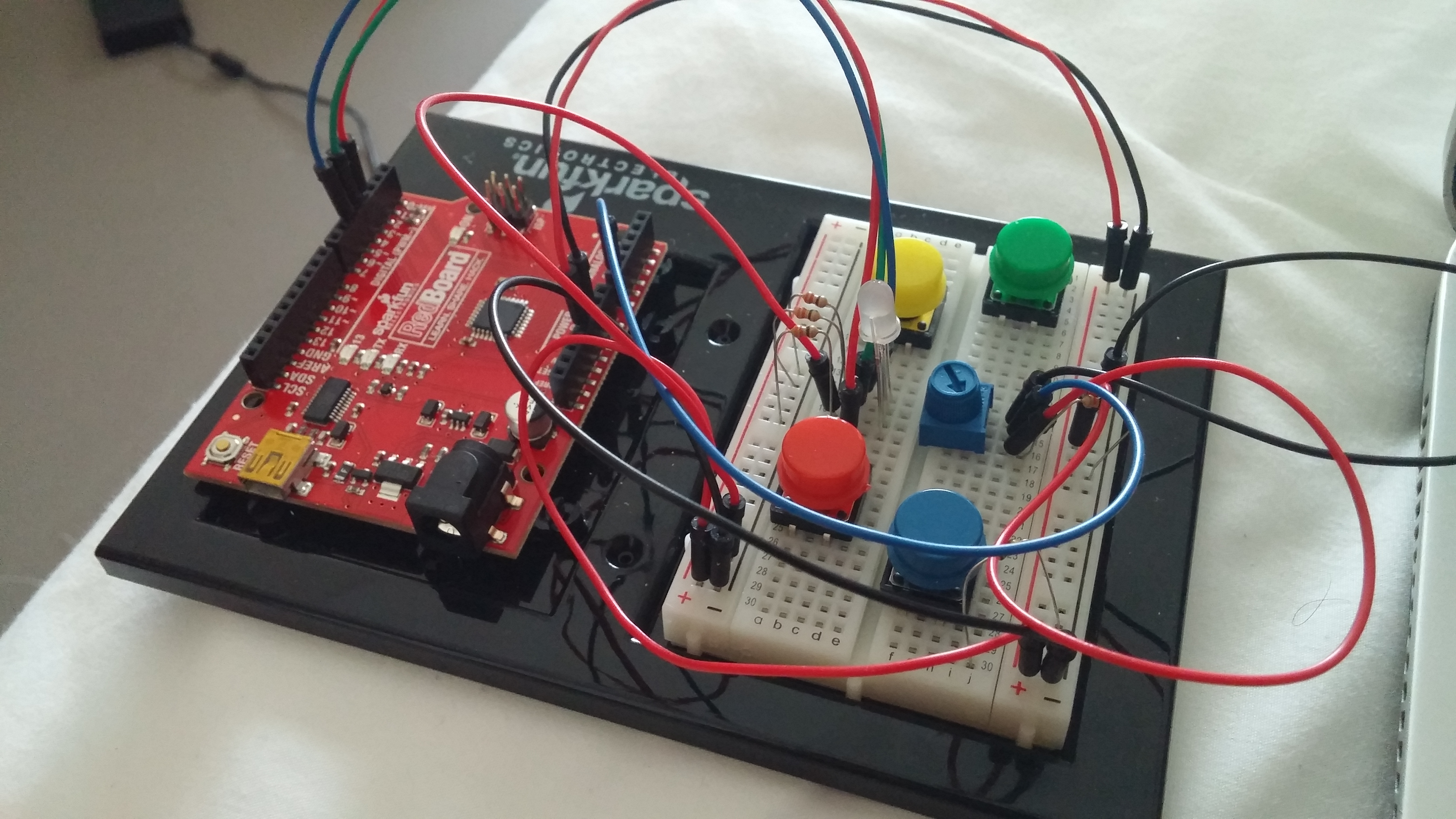
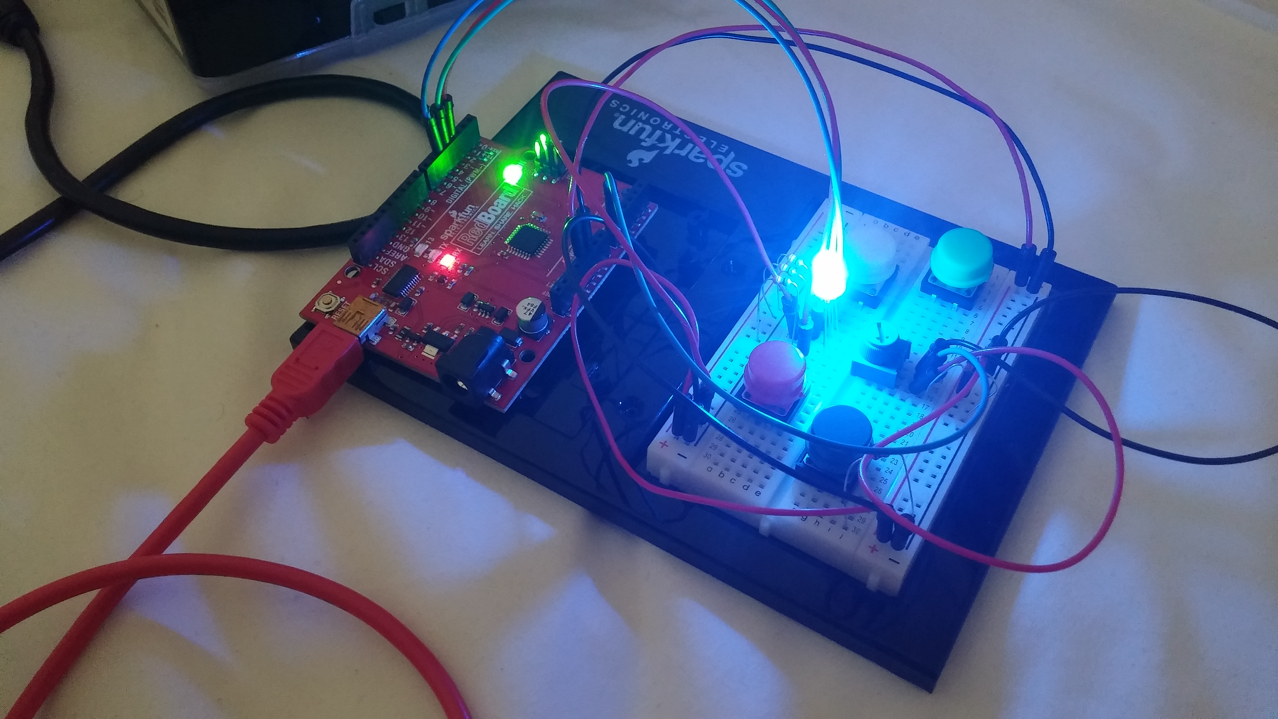
Here are some images of the board itself (off vs on)
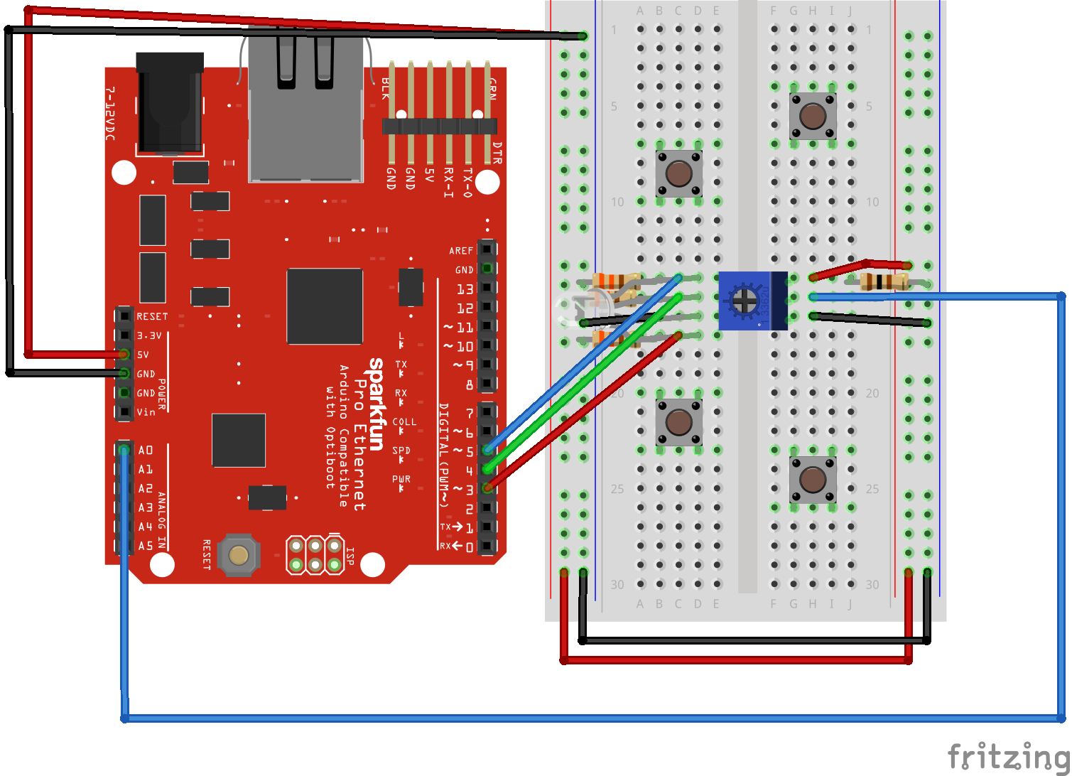
As well as the diagram:
Code:
int potPin = A0;
int greenLED = 4;
int blueLED = 5;
int redLED = 3;
int potVal = 0;

void setup() {
  pinMode(greenLED, OUTPUT);
  pinMode(blueLED, OUTPUT);
  pinMode(redLED, OUTPUT);
  Serial.begin(9600);
}

void loop() {
  potVal = analogRead(potPin);
  if(potVal > 700){
    analogWrite(greenLED, 0);
    if(potVal >= 900){
      analogWrite(blueLED, 255);
      analogWrite(redLED, 0);
    }
    else if(potVal <= 770){
      digitalWrite(blueLED, LOW);
      digitalWrite(redLED, HIGH);
    }
    else{
      analogWrite(blueLED, 100);
      analogWrite(redLED, 255);
    }
  }
  else if(potVal > 300){
    if(potVal >= 500){
      analogWrite(blueLED, 0);
      analogWrite(greenLED, 100);
      analogWrite(redLED, 100);
    }
    else if(potVal < 340){
      analogWrite(blueLED, 0);
      analogWrite(greenLED, 255);
      analogWrite(redLED, 255);
    }
    else{
      analogWrite(blueLED, 0);
      analogWrite(greenLED, 100);
      analogWrite(redLED, 255);
    }
  }
  else{
    if(potVal < 100){
      analogWrite(greenLED, 255);
      analogWrite(blueLED, 0);
      analogWrite(redLED, 0);
    }
    else{
      analogWrite(greenLED, 255);
      analogWrite(blueLED, 100);
      analogWrite(redLED, 0);
    }
  }
  Serial.println(potVal);
}
The way the code basically works is it compares the value the potentiometer returns in several different ranges and depending on which range it falls in, a certain color is emitted. I determined the values by looking at the Serail Monitor and decided at what value I wanted which color to emit. I initially tried modding the potentiometer value and subtracting it from 255 in order to fade but it didn’t turn out exactly how I wanted it to. So with the lack of time, I decided on this. The potentiometer is plugged into the A0 input and PWNs 3, 4, 5 are output for the red, blue, and green pins in the RGB LED. I also placed 330 ohm resistors behind each pin of the RGB LED and a 110 ohm resistor behind the potentiometer power wire. There ya go! Enjoy “All Da Colors”!