
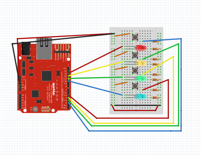
When I thought about the assignment this week, the most obvious way of combining several switches and LEDs seems to be matching them by their colors. But I don’t want to make it boring and just connect components of the same color together. Instead, I created a pattern of lights. What I did was that I placed LEDs and Switches in the opposite order( Red, Yellow, Green, Blue and the reverse) on the breadboard, and made the switches control the blinks of their same-color LEDs, at the same time turn off the adjacent light. Here are the diagram and photo of the layout:

The code looks like this:
pinMode(2, INPUT);
  pinMode(3, INPUT);
  pinMode(4, INPUT);
  pinMode(5, INPUT);

  pinMode(10, OUTPUT);
  pinMode(11, OUTPUT);
  pinMode(12, OUTPUT);
  pinMode(13, OUTPUT);
}

void loop() {
  if(digitalRead(2) == LOW) {
     digitalWrite(13, HIGH);
  } else {
     digitalWrite(13, LOW);
     digitalWrite(10, HIGH);
     delay(100);
     digitalWrite(10, LOW);
     delay(100);
  }
  if(digitalRead(3) == LOW) {
     digitalWrite(12, HIGH);
  } else {
     digitalWrite(12, LOW);
     digitalWrite(11, HIGH);
     delay(100);
     digitalWrite(11, LOW);
     delay(100);
  }
  if(digitalRead(4) == LOW) {
     digitalWrite(11, HIGH);
  } else {
     digitalWrite(11, LOW);
     digitalWrite(12, HIGH);
     delay(100);
     digitalWrite(12, LOW);
     delay(100);
  }
  if(digitalRead(5) == LOW) {
     digitalWrite(10, HIGH);
  } else {
     digitalWrite(10, LOW);
     digitalWrite(13, HIGH);
     delay(100);
     digitalWrite(13, LOW);
     delay(100);
  }
}
It’s pretty fun to see that such simple codes make a big difference in the way the switches work with lights and create multiple color effect. Here’s a video of me experimenting with different patterns on the board: