Fade In and Out – Digital Input

Concept

Imagine you’re in a dark room, and you have two switches in front of you. Each switch corresponds to a color: red and blue. You flip the switch for the red LED, and suddenly, the room is bathed in a warm, red glow. But then you start to wonder: what would happen if you flipped the blue switch too? Would the room turn purple? Would the colors clash or blend together in harmony?

That’s where this code comes in. With just a few lines of code, you can experiment with different combinations of red and blue light and create a range of beautiful color schemes. The code uses analogWrite() to control the brightness of the LEDs, allowing you to create smooth transitions between different levels of light intensity.

But it’s not just about the colors themselves. The code also uses if statements to detect when both switches are flipped at the same time, triggering a unique effect where both LEDs fade in and out together. This creates a mesmerizing effect that can be calming, energizing, or just plain fun to watch.

This code offers a simple and fun way to experiment with LED lighting effects and can be easily customized to create new and unique patterns. For example, you could add more LEDs and switches, or modify the fade amount and brightness values to create different effects. The possibilities are endless!
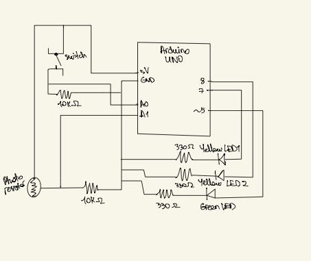
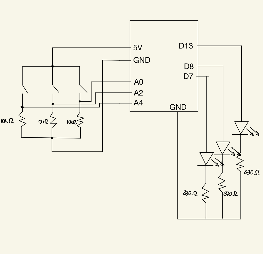
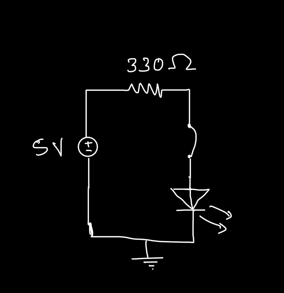
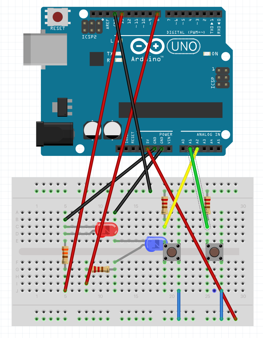
Circuit

Code

// Define the pin numbers for the red and blue LEDs
int redLedPin = 9;
int blueLedPin = 11;

// Define the fade amount and initial brightness for the LEDs
int fadeAmount = 50;
int redBrightness = 0;
int blueBrightness = 0;

void setup() {
  // Set the pin modes for the switches and LEDs
  pinMode(A1, INPUT);
  pinMode(A2, INPUT);
  pinMode(redLedPin, OUTPUT);
  pinMode(blueLedPin, OUTPUT);
}

void loop() {
  // Read the digital input values of the switches
  int switchPositionRed = digitalRead(A2);
  int switchPositionBlue = digitalRead(A1);

  // If the switch for the red LED is pressed, turn on the red LED and turn off the blue LED
  if (switchPositionRed == HIGH) {
    digitalWrite(redLedPin, HIGH);
    digitalWrite(blueLedPin, LOW);
  }
  // If the switch for the blue LED is pressed, turn on the blue LED and turn off the red LED
  else if (switchPositionBlue == HIGH) {
    digitalWrite(redLedPin, LOW);
    digitalWrite(blueLedPin, HIGH);
  }
  // If neither switch is pressed, turn off both LEDs
  else {
    digitalWrite(redLedPin, LOW);
    digitalWrite(blueLedPin, LOW);
  }

  // If both switches are pressed, fade both LEDs in and out
  if (switchPositionRed == HIGH && switchPositionBlue == HIGH){
    // Set the brightness of the red LED and increase/decrease it by the fade amount
    analogWrite(redLedPin, redBrightness);
    redBrightness += fadeAmount;
    if (redBrightness == 0 || redBrightness == 255) {
      // Reverse the fade direction when the brightness reaches 0 or 255
      fadeAmount = -fadeAmount;
    }

    // Set the brightness of the blue LED and increase/decrease it by the fade amount
    analogWrite(blueLedPin, blueBrightness);
    blueBrightness += fadeAmount;
    if (blueBrightness == 0 || blueBrightness == 255) {
      // Reverse the fade direction when the brightness reaches 0 or 255
      fadeAmount = -fadeAmount;
    }
    // Delay for a short amount of time to create the fading effect
  delay(800);
  }

  
}

Video Demonstration


Week 9 – “Sunlight” meter

Concept

My concept for this homework was inspired by the “Oasis” project which imitates a robotic flower that blooms only at night. For my project, I decided to create a”Sunlight” meter for the plants that warns when there’s not enough light around to conduct photosynthesis, and provides a solution in the form of an artificial “sunlight. I use a light sensor as an analog sensor to measure the “sunlight”, and if it will be below the standard brightness threshold needed for photosynthesis, there will be a RED warning light coming from a blinking red LED. Also, I’m also using a switch and two other yellow LEDs. Yellow LEDs are placed around the light sensor to imitate artificial sunlight such that when the user presses the switch (i.e. when there’s not enough light around for the plant to perform photosynthesis), those two yellow LEDs will light up and will provide artificial sunlight for the plant.  P.S. I am not using anything to indicate a plant in this project as I don’t have any plant in my room, but this arduino board can be placed near any plant easily tom measure the light around.


Video Demonstration

Circuit

Code

const int threshold = 150; //threshold for turning on the warning 

void setup()
{
  Serial.begin(9600);
     pinMode(5,OUTPUT); //LED that signals the warning
    
     pinMode(7,OUTPUT); //light LED 1
     pinMode(8,OUTPUT); //light LED 2

     pinMode(A0,INPUT); //switch
     pinMode(A1,INPUT); //light sensor

}
void loop()
{
    //reading analog voltage from the light sensor and storing it in an integer 
    int sensorValue  = analogRead(1);

    //scale sensorValue, which is btw 0 to 1023, to values btw 0 to 255 form analogWrite funtion which only receives  values btw this range
    int brightness = map(sensorValue, 0, 1023, 0, 255); 

    //if the light sensor's brightness value will be less than threshold value
    if(brightness < threshold){

      //make the warning red LED blink
      digitalWrite(5, HIGH);
      delay(500);
      digitalWrite(5, LOW);
      delay(500);

    } else{
      digitalWrite(5, LOW);
    }

  //switch will be a digital sensor
  int switchPosition = digitalRead(A0);

  //when the switch will be pressed, two yellow LEDs surrounding the light sensor will light up, imitating a sunlight
  if (switchPosition == HIGH) {
    digitalWrite(7, HIGH);
    digitalWrite(8, HIGH);
  } 
  else {
    digitalWrite(7, LOW);
    digitalWrite(8, LOW);

  }
}


Week 9: Digital Sensor

Concept

With this assignment, I wanted to implement a traffic light system. The system would light up the red, yellow, and green LED in order, and independently if needed. Below is a circuit diagram for the implementation of the traffic light:

Video

Implementation

There are three major features I included in this assignments:

  1. LED and Switch: I implemented the basic light switch, such that the LED lights up when their respective coloured switch is pressed.
  2. Two Switch: When you press two switches at once, their respective LEDs simulate a FizzBuzz pattern as such: Given a starting index
    1. Both LEDs are turned off when index is divisible by 15.
    2. Both LEDs are turned on when index is divisible by 3 and 5.
    3. LEDs alternate to light up when index is numbers other than ones mentioned above.
  3. Three Switch: When you press three switches at once, they simulate a traffic light, such that they oscillate from red -> yellow -> green and back for a couple of times.

Code:

const int red_in = A0;
const int yellow_in = A2;
const int green_in = A4;

const int red_out = 13;
const int yellow_out = 8;
const int green_out = 7;

const int NUM = 5;
int index;

void light_up(int out) {
  digitalWrite(out, HIGH);
  delay(500);
  digitalWrite(out, LOW);
}

void run_fizzbuzz(int out1, int out2) {
  // checking the state of the buttons, so that we do not run the code when the buttons are not pressed
  int red_switch = digitalRead(red_in);
  int yellow_switch = digitalRead(yellow_in);
  int green_switch = digitalRead(green_in);

  while (red_switch == HIGH || yellow_switch == HIGH || green_switch == HIGH) {
    // regular checking for the button press
    red_switch = digitalRead(red_in);
    yellow_switch = digitalRead(yellow_in);
    green_switch = digitalRead(green_in);

    if (index % 15 == 0) {
      digitalWrite(out1, LOW);
      digitalWrite(out2, LOW);
    } else if (index % 3 == 0 || index % 5 == 0) {
      digitalWrite(out1, HIGH);
      digitalWrite(out2, HIGH);
      delay(300);
      digitalWrite(out1, LOW);
      digitalWrite(out2, LOW);
    } else if (index % 2 != 0) {
      light_up(out1);
    } else if (index % 2 == 0) {
      light_up(out2);
    }

    delay(100);
    digitalWrite(out1, LOW);
    digitalWrite(out2, LOW);
    index++;

    if (index > 20)
      break;
  }
}

void setup() {
  // defining the digital output and digital input for the LEDs
  pinMode(red_in, INPUT);
  pinMode(yellow_in, INPUT);
  pinMode(green_in, INPUT);
  pinMode(red_out, OUTPUT);
  pinMode(yellow_out, OUTPUT);
  pinMode(green_out, OUTPUT);
}

void loop() {
  // Code base for the LEDs
  /*
    OBJECTIVE: Simulate Traffic Light
  */

  // reading the switch state
  int red_switch = digitalRead(red_in);
  int yellow_switch = digitalRead(yellow_in);
  int green_switch = digitalRead(green_in);

  // starting index for FizzBuzz
  index = 1;

  // if all of them are pressed, start simulating a traffic light: RED -> YELLOW -> GREEN. Oscillate between these every few seconds
  if (red_switch == HIGH && yellow_switch == HIGH && green_switch == HIGH) {
    // simulate the traffic light

    // this is a blocking function, as no inputs are registered as long at this loop is running.
    for (int i = 0; i < NUM; i++) {
      light_up(red_out);
      delay(100);
      light_up(yellow_out);
      delay(100);
      light_up(green_out);
      delay(100);
    }

  } else if (red_switch == HIGH && yellow_switch == HIGH && green_switch == LOW) {
    // if the red and yellow switch are turned on, run a FizzBuzz algorithm, such that every multiple of 3, 5 or 15 lights of both the LED, while the LEDs oscillate between each other during other iterations
    run_fizzbuzz(red_out, yellow_out);

  } else if (red_switch == HIGH && yellow_switch == LOW && green_switch == HIGH) {
    // if the red and yellow switch are turned on, run a FizzBuzz algorithm, such that every multiple of 3, 5 or 15 lights of both the LED, while the LEDs oscillate between each other during other iterations
    run_fizzbuzz(red_out, green_out);

  } else if (red_switch == LOW && yellow_switch == HIGH && green_switch == HIGH) {
    // if the red and yellow switch are turned on, run a FizzBuzz algorithm, such that every multiple of 3, 5 or 15 lights of both the LED, while the LEDs oscillate between each other during other iterations
    run_fizzbuzz(yellow_out, green_out);

  } else {
    // light up red when red switch is pressed
    if (red_switch == HIGH)
      digitalWrite(red_out, HIGH);  

    // light up yellow when 
    if (yellow_switch == HIGH)
      digitalWrite(yellow_out, HIGH);

    // light up gree when 
    if (green_switch == HIGH)
      digitalWrite(green_out, HIGH);
  }

  // default state
  digitalWrite(red_out, LOW);
  digitalWrite(yellow_out, LOW);
  digitalWrite(green_out, LOW);
}


Improvement

There is probably a better way to implement the circuit, and the code. The Two Switch features only works when you keep on pressing the button, as opposed to pressing them once and letting the code run. However, this is intended such that pressing two buttons simultaneously by mistake does not lead to the user, waiting for the FizzBuzz to end. However, I have made the Three Switch feature, blocking, such that the user waits for the traffic light animation to end in order to provide other inputs again.


Creative switch

Concept & Method:
I wanted a creative outcome along with a creative switch, so I made a LED hairband for the teddy with a hair straightener as a switch. So I used aluminum foil to make the connections. The tongs of the hair straightener act as a switch that can be operated by stepping on it.

Reflection:
This assignment was definitely one of the most interesting assignments. It made me think of all the possible ways to utilize the materials available but, at the same time, be creative.

Unusual Switch

For this assignment, I created a switch by attaching a pair of scissors to two wires. To improve the conductivity of one wire, I attached a copper foil to it to increase its surface area. I set up a circuit with two LEDs arranged in parallel to ensure they have the same level of brightness.

This type of switch can serve as a means of detecting when a user or player cuts an object. By counting the number of times the LED lights up, the switch can detect how many times the scissors were opened and closed.

.


Unusual switch – Let there be light

For this assignment I have designed a circuit that turns on an LED when the surrounding environment is dark. The light detector serves as a switch that closes the circuit when light is not detected.

The light Dependent resistor LDR functions as a switch in this case. This component is very important as it allows to close the electrical circuit depending on the level of light in the surrounding environment. Such a circuit would be great to light up gardens and outdoor spaces at night automatically without having an actual human manually close the circuit.

Using an electrical component such as an LDR allows the user to save up on electricity for lighting. But it also comes with its drawbacks as sometimes the detector is not as accurate as we would like it to be but in many situations it does the job as in displayed in this project.

Unusual Switch ft. New Roommates

Idea:

Since our two new roommates (whose names are yet to be determined, but for now we call them Pikachu and Purple Banana) arrived, we have been showcasing them on our social media. When I learned about the task, I was immediately aware that I needed to incorporate both of them into the project somehow. I came up with the idea of using Pikachu’s movable ears to create a switch that could be turned on and off, and thankfully, it proved successful in the end. Here are my two new roommates, chilling together:

Concept:

By attaching two coins to the underside of the ears in a specific manner, I established a mechanism such that when the ears were lifted, the coins would not make contact with each other. However, as the ears returned to their resting position, the coins would come into contact, closing the circuit and ultimately causing the bulb to light up. The open and closed switch looks like this:

The final product is converted into a GIF and it looks like this:

Improvements:

As a result of time constraints and other academic obligations, I was unable to experiment further with the project. In the future, I intend to commence the assignment much earlier to allow for more exploration. Additionally, the setup proved to be rather unstable as the wires kept becoming disconnected. To improve this, I plan on using better tape and aluminum foil (the one that covers the yogurt jar does not work apparently).

Lock and Key – Unusual Switch

Concept

I recently decided to embark on a fun and useful project – creating a switch that would only complete the circuit when the key is inserted into the lock of my drawer. Not only does this switch serve a practical purpose by indicating when the key is in the lock, but it’s also a fun addition to my space that sparks conversation and adds a touch of personality.

Method

To create my unique switch, I utilized a simple but effective technique – taping one end of the wire to the lock and the other end to the key. By doing so, when the key is inserted into the lock, the circuit is completed, and the LED bulb lights up.

The use of tape not only makes this project accessible and easy to create, but it also provides a certain level of flexibility. By adjusting the position of the tape and wire, I was able to ensure that the circuit would only be completed when the key is fully inserted into the lock.

Reflection

Overall, I’m really proud of my Arduino-powered switch. It’s a unique and creative way to add some personality to my space while also serving a useful function. And because it’s powered by an Arduino, I can always modify it or integrate it with other devices in the future. I’m excited to see what other projects I can come up with using this Arduino.


Week 8 – Unusual Switch

Concept and Method

For this project, I wanted to make a fun switch, like the mustache one. So, I made two stick/wire figures that held aluminum foil in their hands and when they high five/fist bump, the bulb lights up. The figures are attached to my shoes so I move them using my feet. While this is not a practical switch, I really enjoyed being creative with it!

Future Improvements

Another thing that can be tried later is that instead of making their hands meet, I can attach the wires directly to my shoes so whenever the shoes touch, the bulb will light up.

Unusual Switch

Idea

For this assignment, I struggled to come up with a creative way of connecting a switch without the use of hands. So during one of my stress cleaning episodes in my room, when I tapped on my trash bin to throw something in, the light bulb went off in my mind. That’s why I created a switch that connects when the lid of the bin closes and the light turns on.

How it works

I used the following set up of the circuit. I connected two of the wires with tape because I needed more length for the wire attached to the lid of the bin. A coin is also taped at the end of this wire to increase the surface area of contact between this wire and the one attached to the rim of the bin.

Future improvement

For future implementations, I would somehow want the light to turn on when the lid is open instead and position the wires in a way that it does not disrupt the usage of the bin. Or maybe if a green light turns on if the bin is closed and red light turns on if bin is open.