Given that our task was to fiddle with analog inputs, I figured I could just experiment and do cool stuff using a joystick – also known as an analog stick for a reason. In the end, I connected a joystick to a breadboard in order to control the pitch of a buzzer and the color of an RGB LED!
Category: Observations
Observation assignment.
RGB–Color Control
In this project, I made a circuit with three digital inputs and three digital outputs. There are three switches with different colours and three different colours’ LED lights. Red and green switches together can control the blue LED lights, red and blue switches together control the green LED lights, and the blue and green switches control the red LED lights. If you push the three buttons at the same time, all lights will be on.
Will it turn on?
The video of my project working can be found here. My board works as follows. If I press the first switch, I do not know a priori if the lights will turn on. If I press the second and the first together, the lights will turn on with 100% probability. To randomly turn on the light when the switch is activated, I create two random numbers. The Arduino documentation doesn’t say how its random numbers are distributed, but I assume that they are uniformly distributed between the min and max arguments to the random function. With the two random numbers in hand, I perform a test to see if the first is larger than the second. If it is, then the lights will turn on if the switch is activated. If not, then the lights won’t turn on. The code for my loop() function can be seen here.
Dining etiquette training
My mother always told me not to rest my arms on the table while eating. Although I never saw the merits of such a behavior, I did not object to her mandate and have been careful about where I placed my arms while sitting at the table ever since. Nowadays, table manners seem to have lost their significance. Yet it is never too late to learn some dining etiquette! For my Second Intro to IM assignment, I made an electrical circuit that identifies improper table manners. If only arm rests on the table, a yellow LED lights up, warning the user of her potential transgression. If, however, both arms rest on the table, both red and yellow LED’s start flashing. This is a clear signal to the user to move his arms off the table.
Holiday Lights
For this project, I used yellow, red, and green lights that would turn on to their designated colored switches, and programmed them all to blink in a coordinated pattern with each other. Mostly, when making this project, I just kept thinking about Christmas. And while I couldn’t have snow or presents, I could at least program a tiny version of Christmas lights, while listening to carols during the project for a partial effect.
Apart from the finickiness of the switches and getting the wires to line up on the breadboard, the project was relatively easy to execute.
Initially, I tried to remember everything we learned from Wednesday’s class on programming and switches using photos I took from the class. Once I figured out how to turn on one yellow light with three switches, it became smooth sailing from there on what my errors were and how to fix them.
For this project, I used two red, two green, and two yellow lights, and the pairs were wired in parallel with each other so that they’d both turn on to the same switch input.
When you press the green button, the two green lights will light up at a specific pattern shown below in my coding. Likewise, when pressing the red button, the red lights would light up at a slightly faster speed, to light up whenever the green lights were off. And finally, when pressing the yellow button, the yellow lights will turn on when the other two lights are off. When pressing all three switches, the lights essentially light up in the sequence: green, then red, then yellow.
In order to make the lights work in parallel, the long ends are stuck in the same pin hole, and the short ends are put in the same row as 330 ohm resistors connected to ground. The switches are connected to the ground with a wire, and then a 10K ohmm resister in the row connected to the RedBoard.
When programming, I basically had three sections, with each switch connected to the designated color lights. Below is the chart I used to identify which switch went to which pin since it got confusing after a while with the wiring.
Switch in pin 3 turns on pin 7 green lights
Switch in pin 5 turns on pin 6 red lights
Switch in pin 4 turns on pin 2 yellow lights
Below is a video of how it works, and a copy of my coding:
CODING:
void setup() {
// put your setup code here, to run once:
//SWITCH Green
pinMode(3,INPUT);
// SWITCH Yellow
pinMode(4,INPUT);
// SWITCH Red
pinMode(5,INPUT);
//Red
pinMode(6,OUTPUT);
//Green
pinMode(7,OUTPUT);
//Yellow
pinMode(2,OUTPUT);
}
void loop() {
// put your main code here, to run repeatedly:
if(digitalRead(3) == HIGH){
digitalWrite(7,HIGH);
delay(250);
digitalWrite(7,LOW);
delay(750);
} else {
digitalWrite(7,LOW);
}
if(digitalRead(5) == HIGH){
digitalWrite(6, HIGH);
delay(100);
digitalWrite(6,LOW);
delay(500);
} else {
digitalWrite(6, LOW);
}
if(digitalRead(4) == HIGH){
digitalWrite(2,HIGH);
delay(50);
digitalWrite(2,LOW);
delay(250);
}else{
digitalWrite(2,LOW);
}
}
Please close the door behind you
My roommate is a very considerate person, yet he has a habit of leaving our room door open when he goes to the common room. To be frank, I don’t mind open doors in the daytime. But since I am a light sleeper and get awaken by the slightest rise in light or sound intensity, my roommate’s trips to the common area in the nighttime disrupt my sleep. This is why my first class assignment for Intro to IM features a switch that turns on the LED when the door gets open.
Games!
Disclaimer: things in bold are little nuggets of knowledge that might come in useful. And notes to self, so I don’t make dumb mistakes again.
I love videogames. And colorful blinking lights, obviously. Given that I can’t make a full-blown videogame just yet, I decided to start with something simpler (but challenging given that this is just my second project). The goal: build and program a memory game (Simon).
Step 1 was making the LEDs actually turn on. Four buttons acted as inputs, and the LEDs were connected as four outputs. I could have as well made the LEDs turn on via the physical switches, but that would have defeated the purpose of the asignment. Nothing too different from what we did in class. It was simple enough to code, but it didn’t work out at the first go. My brain forgot to plug the outputs to ground (way to go – brain-five!). You can see the result here: https://youtu.be/yzMvNNp7sp4
And then the fun part started. Continue reading “Games!”
FTDI drivers
Tableware–Chopsticks and Spoon
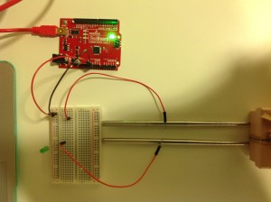
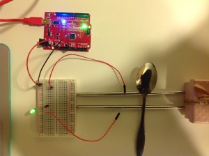
My circuit which I only added chopsticks and a spoon into is quite simple. To make the light on, we only need to make sure that the voltage assigned to the light will be around its rated voltage. In addition, having a loop is quite important.
We can’t use common switch, so we’ll try something new. At first, I was going to find something which is made of metal that can conduct electricity. Then I chose my necklace and used it as conductor in my circuit, however, the light was still off and it didn’t work at all. Maybe the necklace has a quite large resistance, which leads to the light does not have enough voltage to be on. Or the necklace’s material does not have a good conductive in the circuit.
The second time, I chose nail clippers. When I cut it, I thought the top of the nail clippers can be closed to form a loop, maybe it can be a part of my circuits. Nevertheless, the light will always be on when I use the nail clippers as a connection.
The third time, I had a very simple idea by using chopsticks and spoon. Luckily, they naturally became a close circuit with GREAT conductive ability.
Recycle!
So as to be caring, environmentally friendly citizens, my roommates and I have agreed to use a seperate trash bin for plastic. However, banana peels and remnants of humus kept landing in the recycling bin, despite my persistance in placing the ‘Plastic’ label back on it again and again. As the label proved to be an inefficient solution, I thought a warning light could solve the problem.
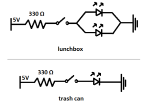
Although I was aiming for a light that goes up each time someone opens the trash can, I started out with a smaller project, a lunchbox. First, I fixed two small pieces of conductive fabric to the ends of two longer wires with conductive tape (so that each wire had one end with the fabric on it, and one end ‘open’). Then the conductive fabric parts were fixed to the back of the lunchbox so that they would touch when the box is opened (see video).
Happy that my idea works, I made two longer wires with conductive fabric at their ends and I soldered two long wires to the two ends of a LED for my trash bin. Having disassambled the bin, I fixed one of the fabric pieces on its bottom, and the other one at the end of the pedal (in a way that they would touch when the pedal is stepped upon).
The sound of the following footage is a happy accident, and not part of my work (unfortunately).
See the two circuits in the picture below.


