Idea:
For my musical instrument, I thought it would be cool to create a DJ because I wanted to try and incorporate pretty much all the components we learned up until now.
This was my idea for the components:
- The Servo Motor could act as the DJ and this can be controlled via the light sensor. So you could move your hand up and down and it would map out the Servo rotation. Additionally, I thought it would be cool to add some cool lights to kinda give that disco vibe so as you change your hand position over the light sensor, the lights would change too.
- I added a button and a potentiometer and this would essentially play the songs that a regular DJ would play. So essentially, I have a library of songs on the Arduino code, and depending on which position the potentiometer is on, when pressed the button, it would play that appropriate song.
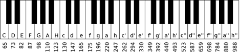
For now, I only added 4 songs. How this worked is, I borrowed the “pitch.h” header file that we used in class to map out the note pitches and frequencies. From that, I constructed several arrays which would be the different songs. Then that would be played out loud through the buzzer.
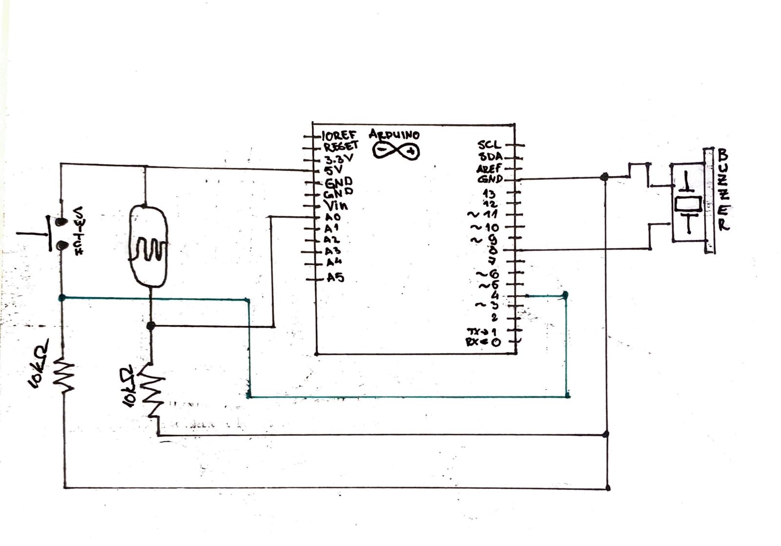
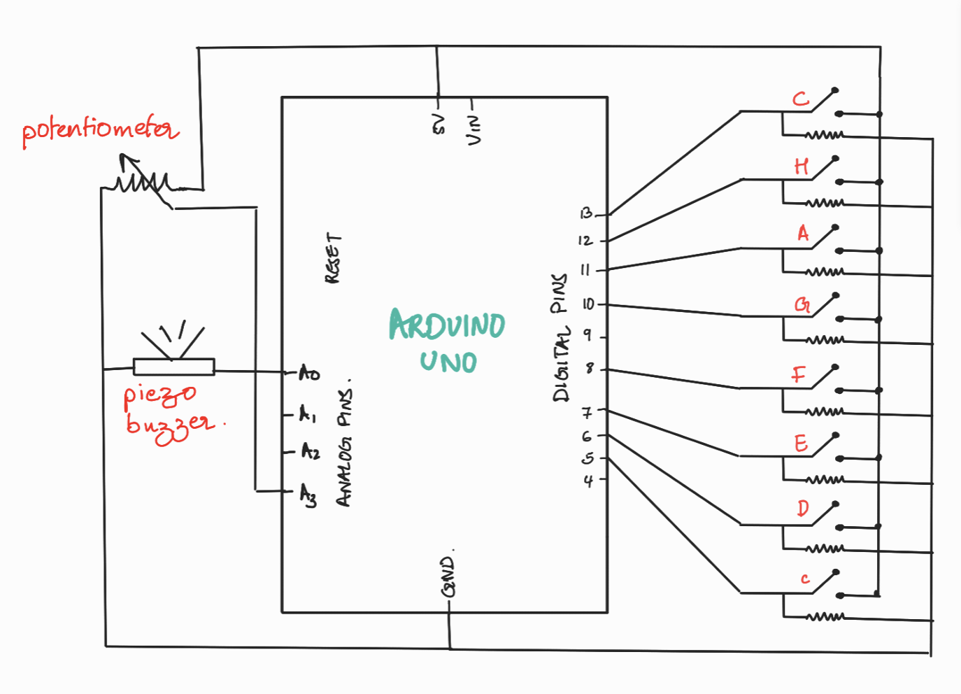
Schematic: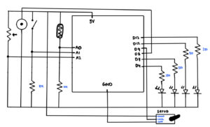
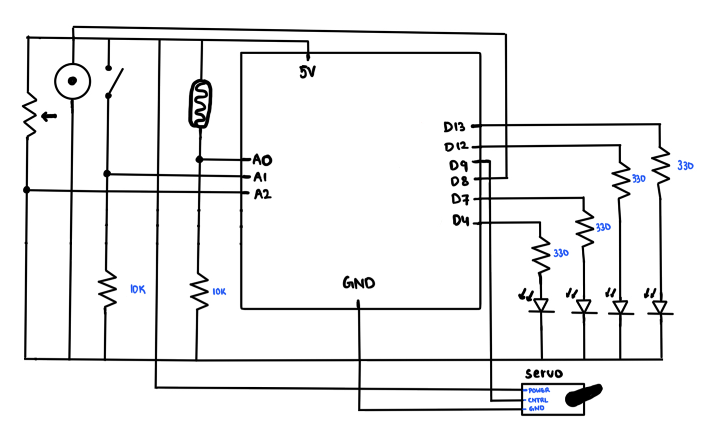
Arduino Code:
#include <Servo.h>
#include "pitches.h"

const int LightSensorPin = A0;
const int PotPin = A1;
const int Button = A2;

const int ServoPin = 9;
const int BuzzerPin = 8;
const int YPin1 = 13;
const int YPin2 = 12;
const int YPin3 = 7;
const int YPin4 = 4;

const int Melody1_Size = 13;
const int Melody2_Size = 11;
const int Melody3_Size = 30;
const int Melody4_Size = 29;

Servo DJ;

//Melodies:
int melody1[] = {NOTE_E4, NOTE_D4, NOTE_FS3, NOTE_GS3, NOTE_CS4, NOTE_B3, NOTE_D3, NOTE_E3, NOTE_B3, NOTE_A3, NOTE_CS3, NOTE_E3, NOTE_A3};
int melody2[] = {NOTE_C4, NOTE_DS4, NOTE_F4, NOTE_FS4, NOTE_F4, NOTE_DS4, NOTE_C4, 0, NOTE_AS3, NOTE_D4, NOTE_C4};
int melody3[] = {NOTE_A3, NOTE_B3, NOTE_D4, NOTE_B3, NOTE_FS4, NOTE_FS4, NOTE_E4, 0, NOTE_A3, NOTE_B3, NOTE_D4, NOTE_B3, NOTE_E4, NOTE_E4, NOTE_D4, NOTE_CS4, NOTE_B3, 0, NOTE_A3, NOTE_B3, NOTE_D4, NOTE_B3, NOTE_D4, NOTE_E4, NOTE_CS4, NOTE_B3, NOTE_A3, NOTE_A3, NOTE_E4, NOTE_D4};
int melody4[] = {NOTE_E4, NOTE_D4, NOTE_C4, NOTE_D4, NOTE_E4, NOTE_E4, NOTE_E4, 0, NOTE_D4, NOTE_D4, NOTE_D4, 0, NOTE_E4, NOTE_G4, NOTE_G4, 0, NOTE_E4, NOTE_D4, NOTE_C4, NOTE_D4, NOTE_E4, NOTE_E4, NOTE_E4, NOTE_E4, NOTE_D4, NOTE_D4, NOTE_E4, NOTE_D4, NOTE_C4};

//Melody Durations
int m1_durations[] = {8, 8, 4, 4, 8, 8, 4, 4, 8, 8, 4, 4, 2};
int m2_durations[] = {4, 4, 4, 4, 4, 4, 4, 2, 8, 8, 2};
int m3_durations[] = {8, 8, 8, 8, 3, 3, 4, 3, 8, 8, 8, 8, 3, 3, 2, 8, 8, 4, 8, 8, 8, 8, 3, 3, 2, 8, 4, 4, 2, 4};
int m4_durations[] = {4, 4, 4, 4, 4, 4, 4, 4, 4, 4, 4, 4, 4, 4, 4, 4, 4, 4, 4, 4, 4, 4, 4, 4, 4, 4, 4, 4, 4};


void setup() {
  Serial.begin(9600);
  DJ.attach(ServoPin);                 //Pin for the Servo Motor

  //Analog Inputs
  pinMode(LightSensorPin, INPUT);     //Pin for the Light Sensor
  pinMode(PotPin, INPUT);             //Pin for the Potentiometer
  pinMode(Button, INPUT);             //Pin for the Button

  //LED Pins
  pinMode(YPin1, OUTPUT);
  pinMode(YPin2, OUTPUT);
  pinMode(YPin3, OUTPUT);
  pinMode(YPin4, OUTPUT);
}

void loop() {
  //Reads all the necessary values from the analog input pins
  int LightValue = analogRead(LightSensorPin);
  int PotValue = analogRead(PotPin);
  int ButtonValue = analogRead(Button);
  int discoLight = LightValue;    //Variable for changing the lights

  //Writing the Light Sensor data onto the Servo:
  LightValue = map(LightValue, 0, 1023, 0, 180);

  //Converting the potentiometer values to the according melody
  int Melody = map(PotValue, 0, 1023, 0, 4);
  DJ.write(LightValue);

  //Writing the data for the disco lights:
    if(discoLight < 550 && discoLight >= 450) {
    digitalWrite(YPin1, HIGH);
    digitalWrite(YPin2, LOW);
    digitalWrite(YPin3, LOW);
    digitalWrite(YPin4, LOW);
  }

  else if (discoLight < 450 && discoLight >= 350){
    digitalWrite(YPin1, LOW);
    digitalWrite(YPin2, HIGH);
    digitalWrite(YPin3, LOW);
    digitalWrite(YPin4, LOW);
  }

  else if(discoLight < 350 && discoLight >= 250) {
    digitalWrite(YPin1, LOW);
    digitalWrite(YPin2, LOW);
    digitalWrite(YPin3, HIGH);
    digitalWrite(YPin4, LOW);
  }

  else if(discoLight < 250) {
    digitalWrite(YPin1, LOW);
    digitalWrite(YPin2, LOW);
    digitalWrite(YPin3, LOW);
    digitalWrite(YPin4, HIGH);
  }

  //Offsets the PotValue to 3 in case it reaches 4, for stabilization
  if(PotValue == 4) {
    PotValue = 3;
  }
  Serial.println(Melody);

  //If the button is pressed, depending on the potentiometer value, it will play the according melodies.
  if(ButtonValue > 1000) {
    if(Melody == 0) {
      MelodyPlayer(melody1, m1_durations, Melody1_Size, LightValue);
    }

    else if(Melody == 1) {
      MelodyPlayer(melody2, m2_durations, Melody2_Size, LightValue);
    }

    else if(Melody == 2) {
      MelodyPlayer(melody3, m3_durations, Melody3_Size, LightValue);
    }

    else {
      MelodyPlayer(melody4, m4_durations, Melody4_Size, LightValue);
    }

  }
  delay(50);
}

//This function plays the melody that it was assigned to it. It also registers the LightValue so that way the DJ can play while the song is also playing.
void MelodyPlayer(int melodyNum[], int melodyDur[], int melodySize, int LightValue) {
    for (int thisNote = 0; thisNote < melodySize; thisNote++) {
      LightValue = analogRead(LightSensorPin);
      LightValue = map(LightValue, 0, 1023, 0, 180);
      DJ.write(LightValue);

      //To calculate the note duration, take one second divided by the note type.
      //Ex: quarter note = 1000 / 4, eighth note = 1000/8, etc.
      int noteDuration = 1000 / melodyDur[thisNote];

      tone(8, melodyNum[thisNote], noteDuration);
      //To distinguish the notes, set a minimum time between them.
      int pauseBetweenNotes = noteDuration * 1.30;
      delay(pauseBetweenNotes);

      //Stop the tone playing:
      noTone(8);
    }
}
Video:
Improvements:
I feel that when the song is playing, because it enters the for loop, the sensors stop reading in data, meaning the servo motors and the LED lights stop reading in data so it won’t move while the song is playing. My solution was to pass the LightValue so that the motor would at least move while the song is playing on beat. But if the motor and lights could move while the song is playing freely like it does with no song playing, that would be an amazing improvement.