As you may have noticed, I had some difficulties in coming up with a project idea for so long, it took me 2 weeks… I had even started creating my first idea, which was about creating a 3D controller for a game. Honestly, I found this idea on the internet and just wanted to create my own snake game to use this controller. Yet the idea was really “half-baked” and I was not really excited about creating it, I thought that having a particular idea is enough to implement it. Yet, apparently not for me. Having a lot of struggles with the project idea, I talked to Professor Aaron, who emphasized that there should be a part of me in the project. Being lost for a couple of weeks, I got eventually inspired by the song of the Kazakh artists (https://www.youtube.com/watch?v=iHh_DoqE2fY). The song made me think about the nature of our country and suddenly I started to have ideas about creating an interactive experience. Then, I decided to discuss the idea with Professor Aaron, who helped me to have a more refined view of the project. I got really excited about implementing my final idea for the project
I booked iPad from the lab to create some visuals (that was my first time using it and I really enjoyed using its possibilities for creative purposes). I found some photos of our nature on the internet and smudged the colours to create a painting effect.
Also special thanks to Jack for expanding my idea of creating physical interaction with the 3D printed grass. He kindly guided me through the process of using the 3D printer for the first time.
I had some struggles in controlling the ZX detection sensor, which should work when a user waves a hand over the grass to turn on the led strip and initiate the horse’s running. First of all, I used coordinates to be able to control hand detection. However, the sensor could give some random values sometimes and the horse would demonstrate to me its audacity to run on its own and not “obey” the movements of my hand. Therefore, instead of using the library example with coordinates, together with the Professor’s help, we discovered the gesture example. As opposed to the previous library example, it could be easily controlled due to any gesture the sensor could be exposed to.
Also, I have a potentiometer, which is hidden by the sun and moon pictures. I am using it to change the background of the program so that there is a transition from day to night. Compared to the sensor, the potentiometer was less “capricious” :))
Result 🤸♀️
I am really glad about the final result! Thank you to the whole IM Lab team and Professor Aaron for helping me throughout this process! I learned a lot of interesting and practically useful things this semester. I had several hardships, but it was a rewarding experience 🙂
#include <Wire.h>
#include <ZX_Sensor.h>
#include <FastLED.h>
#define LED_PIN     5
#define NUM_LEDS    25
#define BRIGHTNESS  64
#define LED_TYPE    WS2811
#define COLOR_ORDER GRB
CRGB leds[NUM_LEDS];
int currentVal = 0;

const int ZX_ADDR = 0x10;  // ZX Sensor I2C address

// Global Variables
ZX_Sensor zx_sensor = ZX_Sensor(ZX_ADDR);
uint8_t x_pos;
uint8_t z_pos;

CRGBPalette16 currentPalette;

GestureType gesture;

void setup() {
  delay( 3000 ); // power-up safety delay
  FastLED.addLeds<LED_TYPE, LED_PIN, COLOR_ORDER>(leds, NUM_LEDS).setCorrection( TypicalLEDStrip );
  FastLED.setBrightness(  BRIGHTNESS );

  // Initialize Serial port
  Serial.begin(9600);

  zx_sensor.init();

  while (Serial.available() <= 0) {
    Serial.println("0,0");
    delay(300);
  }
}


void loop()
{

  FastLED.show();

  if ( zx_sensor.gestureAvailable() ) {
    gesture = zx_sensor.readGesture();
    switch ( gesture ) {
      case RIGHT_SWIPE:
        currentPalette[0] =  CRGB(255, 255, 0);
        x_pos = 0;
        break;
      case LEFT_SWIPE:
        x_pos = 1;
        currentPalette[0] =  CRGB(0, 255, 0);
        break;
      default:
        break;
    }
  }

  for (int i = 0; i < NUM_LEDS ; i++) {
    // let's set an led value
    leds[i] = currentPalette[0];//CHSV(hue++, 255, 255);

  }

  while (Serial.available()) {
    byte inComing = Serial.read();
    if (inComing == '\n') {

      int sensor = analogRead(A0);
      delay(1);

      Serial.print(x_pos);
      Serial.print(',');
      Serial.println(sensor);
    }
  }
}
I really wanted to make something related to basketball, since I am a big fan of the sport. So I decided to make a mini basketball shooting game, similar to the ones seen in arcades. My game consists of a small boxy frame in which there is a hoop I made. The player basically has to shoot the ball into the hoop from a fair distance. Each time the ball goes through the hoop, it hits the flex sensor and changes its values. Each time a change in the flex sensor values is detected, the player is awarded 3 points. There are no point deductions for misses. There is also a timer of 60 seconds after which a buzzer sounds and the game ends. Then the player can see their score, the high score, and has the option to play again.
Game Box Frame
I made a boxy frame (see game demo below) to hold up the hoop and also have a ramp so that the ball would roll back towards the player which makes it more convenient. Ideally, the box should have been bigger to allow more space for the ball to fall on the ramp so that most misses would still fall within the box and the ball would roll back to the user. However, I did not think of this when designing the box. I wanted to use my monitor to display the p5js sketch behind the box frame just so that the score would be directly behind the target and the player would not have to look to the side each time they want to see the score or the time left.
I made the hoop using a plastic tube as the pole holding it up, a piece of cardboard as the backboard, and a transparent plastic cup as the rim. The ball is just a ping pong ball that I had in my room. To assemble the carboard pieces together, I used a glue gun and I drilled a hole into the ramp to insert the plastic tube into. The hole I drilled was smaller than the diameter of the tube so I forced the tube into the hole. This was to make sure the tube fits perfectly and is tightly held up. The two holes on the side only exist to make it easier for me to carry it.
P5JS Implementation
I started my project by making the game class, with different game states so I can transition between the menu screen and game screen easily, and to make it easier to restart the game when necessary. Doing this also lets me do different things whenever the mouse is pressed at different stages of the game. I then added all the necessary variables for all the images, sounds, the sprite sheet, arrays and other necessary variables.
Then I made the game full screen when the user clicks the starting screen, by resizing the canvas and using fullscreen(). While this worked fine on my laptop screen, it just would not fill up my entire monitor screen (see game demo below), even when I tried hard coding the canvas size values with the monitor resolution.
I used a sprite sheet of a bouncing basketball I found online on the menu screen to make the menu screen more dynamic and not just a boring old background.
Also, I had an array of sounds from audio clips of a famous NBA commentator, Mike Breen who has iconic lines. Each time a shot is made, a rando sound from the array is played to provide feedback to the user. When the game ends, there is a buzzer sound played to let the user know the game is over.
Here is the p5sj code:
let alpha = 255;
let game;
let backgroundMusic;
let spritesheet;
let bballSprite = [];
let step = 0;
let x = 0;
let w;
let h;
let startTime = 0;
let cd = 1;
let gameTime = 5;
let fade = 0;
let prevVal = 0;
let newVal = 0;
let time = 0;
let sounds = [];
let crowdSound;
let music;

function preload() {
  // backgroundMusic = loadSound("assets/background.mp3");
  spritesheet = loadImage("assets/sprite.png");
  crowd = loadImage("assets/background2.jpg");
  menu = loadImage("assets/menu.jpg");
  font = loadFont("assets/font.ttf");
  buzzer = loadSound("assets/buzzer.wav");
  for (let i = 1; i < 7; i++){
    sounds[i-1] = loadSound("assets/" + i + ".wav");
  }
  crowdSound = loadSound("assets/crowdSound.wav");
  music = loadSound("assets/music.wav");
}

function setup() {
  createCanvas(600, 600);
  textSize(18);
  setUpSerial();
  game = new Game();
  textAlign(CENTER);
  rectMode(CENTER);
  spritesheet.resize(spritesheet.width / 2, spritesheet.height / 2);
  w = spritesheet.width / 6;
  h = spritesheet.height;
  for (let i = 0; i < 6; i++) {
    bballSprite[i] = spritesheet.get(i * w, 0, w, h);
  }
  textFont(font);
}

function draw() {
  if (!serialActive) {
    fill(255);
    text("Press Space Bar to select Serial Port", 20, 30);
  } else {
    //backgroundMusic.play();
    background(255);
    if (game.state == 0) {
      game.click();
    } else if (game.state == 1) {
      game.menu();
    } else if (game.state == 2) {
      game.countdown();
    } else if (game.state == 3) {
      game.game();
    } else if (game.state == 4) {
      game.endScreen();
    }
  }
}

function mousePressed() {
  if (game.state == 0) {
    music.setVolume(0.5);
    music.loop();
    let fs = fullscreen();
    fullscreen(!fs);
    resizeCanvas(displayWidth, displayHeight);
    game.state++;
  } else if (
    game.state == 1 &&
    mouseX < width / 4 + width / 8 &&
    mouseX > width / 4 - width / 8 &&
    mouseY < (5 * height) / 9 + height / 14 &&
    mouseY > (5 * height) / 9 - height / 14
  ) {
    music.stop();
    game.state++;
    startTime = frameCount;
  } else if (
    game.state == 4 &&
    mouseX < width / 2 + width / 4 &&
    mouseX > width / 2 - width / 4 &&
    mouseY < (7 * height) / 9 + height / 5 &&
    mouseY > (7 * height) / 9 - height / 5
  ) {
    game.state = 2;
    game.score = 0;
    cd = 3;
    gameTime = 60;
  }
}

function keyPressed() {
  if (key == " ") {
    setUpSerial(SELECT_PORT);
  }
}

function readSerial(data) {
  if (data != null) {
    let fromArduino = split(trim(data), ",");
    if (newVal!=prevVal){
        prevVal = newVal;
    }
    if (fromArduino.length == 1) {
      newVal = fromArduino[0];
      //print (newVal);
    }
    writeSerial(0);
  }
}

class Game {
  constructor() {
    this.state = 0;
    this.score = 0;
    this.highScore = 0;
    this.time = 60;
    this.highScore = 0;
  }

  click() {
    push();
    background(0);
    fill(255);
    textSize(width / 10);
    text("Click to start", width / 2, height / 2);
    pop();
  }

  menu() {
    if (frameCount % 5 == 0) {
      step++;
      if (step == 6) {
        x += w;
        step = 0;
      }
      if (x >= width) {
        x = 0;
      }
    }
    push();
    imageMode(CORNER);
    image(menu, 0, 0, width, height);
    //backgroundMusic.play();
    pop();
    push();
    image(bballSprite[step], x, (2 * height) / 3);
    if (fade < 255) {
      fade += 2;
    }
    fill(0, 150);
    rect(width / 4, (5 * height) / 9, width / 4, height / 7, 20);
    rect(width / 2, height / 7, 5*width / 6, height / 6, 20);
    fill(255, fade);
    textSize(width / 10);
    textFont(font);
    text("3 POINT SHOOTOUT", width/2, height/5);
    text("Start", width / 4, (3 * height) / 5);
    pop();
  }

  countdown() {
    push();
    background(0);
    fill(255);
    textSize(width / 12);
    text(cd, width / 4, height / 2);
    if ((frameCount - startTime) % 60 == 0) {
      cd--;
    }
    if (cd == 0) {
      crowdSound.setVolume(0.5);
      crowdSound.loop();
      this.state++;
      startTime = frameCount;
    }
    pop();
  }

  game() {
    push();
    imageMode(CORNER);
    image(crowd, 0, 0, width, height);
    pop();
    push();
    textSize(width / 15);
    if ((frameCount - startTime) % 60 == 0) {
      gameTime--;
    }
    text("Time left: " + gameTime, width / 4, height / 8);
    text("Score: " + this.score, width / 4, (10 * height) / 11);
    if (newVal < prevVal - 7 && time < frameCount - 30){
      let rand = int(random(6));
      sounds[rand].play();
      this.score+=3;
      time = frameCount;
    }
    if (gameTime == 0) {
      buzzer.play();
      this.state++;
      if (this.score > this.highScore) {
        this.highScore = this.score;
      }
    }
    pop();
  }
  endScreen() {
    push();
    imageMode(CORNER);
    image(crowd, 0, 0, width, height);
    pop();
    push();
    fill(255);
    textSize(width / 12);
    text("Game Over", width / 2, height / 2);
    text("Score: " + this.score, (1.5 * width) / 7, height / 4);
    text("High Score: " + this.highScore, (5 * width) / 7, height / 4);
    fill(255);
    text("Play Again", width / 2, (7 * height) / 9);
    pop();
  }
}
Here is the p5js sketch (the embedded version does not seem to work well and I can’t figure out why):
Arduino Implementation
My project only used one flex sensor so my circuit and code were fairly simple. The circuit only consisted of the flex sensor and a resistor. The flex sensor is connected to analog input. The Arduino code was basically just receiving the flex sensor value and sending it to p5js.
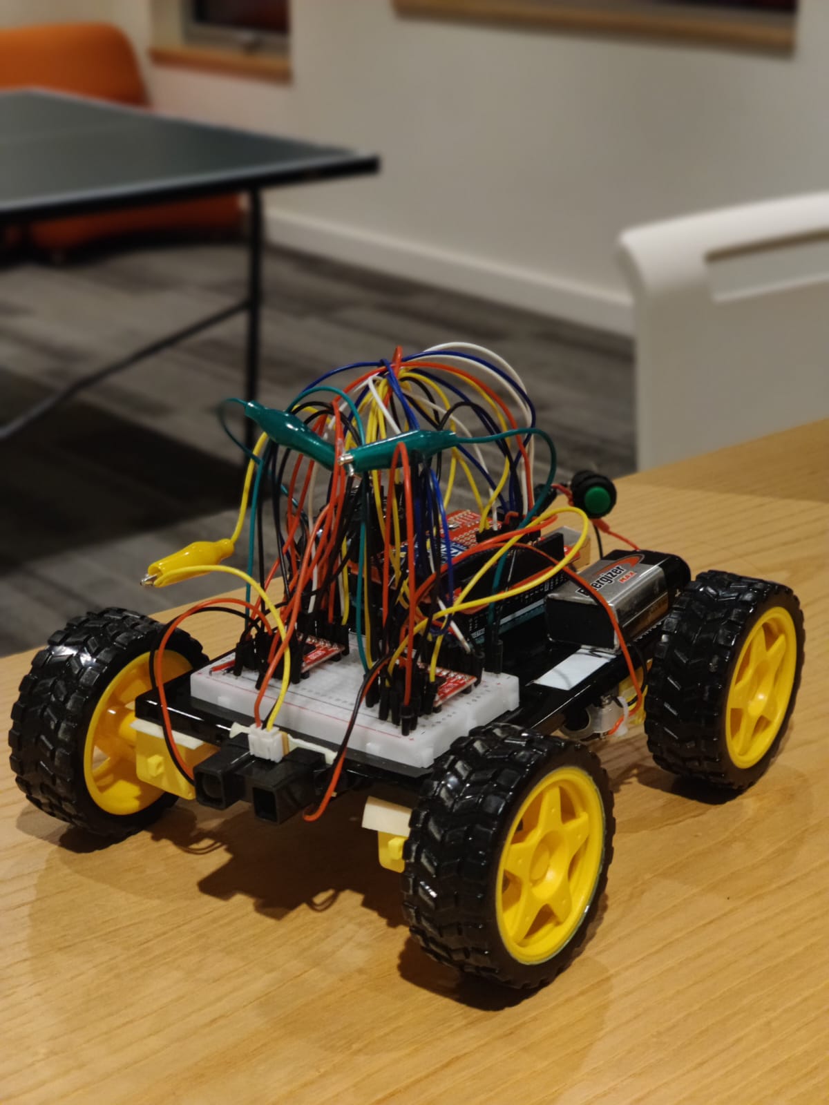
We built a remotely controlled car which the user was able to control remotely using wireless transmission from P5.js. The user controls the car using arrows keys through p5js and spacebar for braking.
Arduino Components
Arduino Uno (we are going to move it to the MEGA board)
Infrared Range Sensor
4 Wheels
4 Motors
2 SparkFun Motor Drivers – Dual TB6612FNG
9V DC Battery
Battery Holder
XBee Explorer USB 06
SparkFun – XBee Shield for Arduino 04
XBee 1mW Trace Antenna – Series 1 01
XBee 1mW Trace Antenna – Series 1 07
1 On/Off Switch
Implementation
We started by taping the motors using double sided tape and sticking it to the acrylic sheet. Then we connected the wheels to the motor and wired it to the motor driver. We manage to fit all the pins on the Arduino Uno and after couple hours of figuring out the wiring we got both the motor driver on the breadboard. Then came the challenging part of getting the pins defined correctly in the code and using the example code to build up on our car driving code.
We made the car so that it can move in all directions, using two motor drivers and four motors (4 Wheel Drive). This allows the user to control the car’s movement direction using arrow keys on P5.js through Serial Communication with the Arduino connected to the car. In this way, we have the manual driving mode fully working now.
Serial Communication
The p5.js is serially transmitting a direction flag (integer) that is indicating the driving direction and the Arduino is reading this flag and using switch statements to manipulate the motors in order to make the car move in a certain direction. These switch statements control the motors’ speeds and rotation directions.
We decided to manually control the movement of the car – without an IR remote controller – because this is the most functionally important part of this project. We spent the most of our time in the beginning trying to understanding how the motors work and what possibilities there are coding features for motors in Arduino.
The P5js sketch has an instructions page with the driving instructions and port connection instructions. After connecting with USB port the user can start driving the car using the arrow keys allowing the car to move around and detect and respond to obstacles.
Object Detection
For now, we have implemented object detection in only the forward direction using the IR Range Sensor. Any obstacle detected approximately 40 cm in front of the car causes the car to come to a halt. At this point, the user can only move the car in the backward direction to avoid the obstacle altogether. We spent most of our time working on this functionality in this project – more on this in challenges.
Wireless Transmission
We then moved on to adding wireless transmission using the XBee shield and chip we checked out as per the Professor’s suggestion. One of the XBee chips was connected with P5Js and sent out data from P5. The other chip was connected with the Arduino on the car and received the signals sent out from P5. This transmission also went both ways. Using this scheme, we were able to make our car function fully remotely.
Challenges
Initially, we were using an Ultrasonic Sensor that comes with the Sparkfun Arduino Kit for this purpose. However, there was a long delay time associated with its working and the system was not very response – especially after integrating the XBee chip for wireless transmission later on. This is why we used the more responsive IR Range Sensor and polished the obstacle detection functionality to the point that it works as originally intended.
We also struggled a lot with XCTU and the firmware issue which we couldn’t resolve and thus couldn’t get the XBEE to be configured with each other and setup their PAN IDs. This why despite the handshake functions our wireless communication would break from time to time and the packets would get lost instead of being sent to the car.
Since my last post, I have worked on the circuit, the cardboard frame, and the hoop. I managed to put everything together and finish the main part of the game hardware. I pasted two cardboard planks with holes in them for me to carry the setup around, to a ramp which exists to let the ball roll down back to the user after it goes in the hoop.
Below is the video of me testing out if the flex sensor works correctly. It may be hard to see in the video, but each time the ball goes in the hoop, the value of the flex sensor changes by about 50, so I plan to detect a change of around 20-30 in my code to sense when the ball goes in and add the score accordingly and trigger the corresponding sounds. I can’t rely on detecting any change in the flex sensor values, because the hoop is a bit shaky and this makes the values fluctuate by 1 or 2 when nothing is happening.
Things left for me to do
Add the necessary sounds when the user scores
Add music for the game
Make sure the game setup is durable and won’t eventually break or come apart
Figure out if and how I will use a monitor behind the hoop
Progress:
I will agree that I am pretty behind on my final project. I have to work on the art designs and color modes. I am planning to use like 9 sensors and each sensor controls 1/9 of the presentation page. Basically dividing the canvas into 9 squares and controlling the design pop up using the sensors. I am yet to decide on which design to use because of a few errors that I encountered. So, when I create a design, I use “translate()” and then append the design into an array and run it. And then when I have to append another design, the second time translate function makes the design a little weird.
Here’s a short demo of how the sensors would work. Professor suggested using buttons but I wanted the design feel to be like a touch bar. Here, touching the piezo disks changes the design.
Mostly done with the programming part over the gameplay algorithms, except for the communication of the Arduino circuit with p5js. The game is totally playable through keyboard controls: spacebar – item interaction, arrow keys – player movement.
The collection of assets is completed through free assets images and self-made images through Clip Studio Paint and Adobe Photoshop.
In progress:
Thumbnail of the game (a background picture to be used for the start menu)
Create Circuit Map before constructing the interactive structures.
Objectives left:
Algorithm for collision with objects to restrict character movement
Connection with Circuit
Wood miniature of the room in the game
Test on several people to investigate the game’s difficulty (of the puzzle). => Anyone who sees this article, don’t be afraid to try out my game!! (It’s made to be very difficult to clear in a 5-minute time limit.)
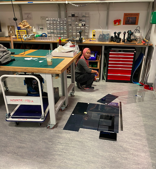
As you could observe in our previous post, we still had a lot to do on the construction of Dance Breaker. Thus, the initial days after last update were spent advancing as much as we could in order for user testing to be the most useful. This, of course, considering the Lily’s capstone written report was due on May 4th. During the break, we finished the illustrator sketches and cut with Kyles help. We, however, ran into a small time delay, as we did not factor that there would be no IM lab assistants during the Eid break. Regardless, after many hours of hard work, we were able to build a prototype for one of the pedals, and combine it with the current code.
User Testing 1: Dancing Mat Feedback & Help 💡
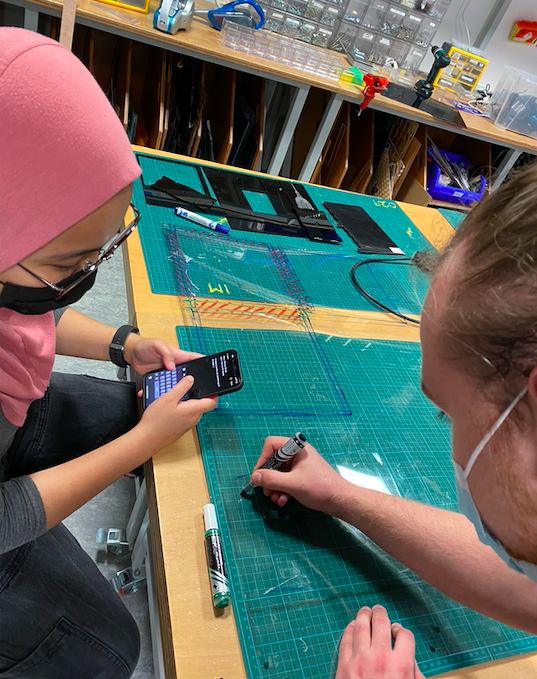
We came to Kyle, an expert in the IM lab with our prototype and soldered sensors (we finished them during last class). He pointed out a lot of design flaws and elements we had not considered, and spent a full afternoon helping us improve the design and prepare all of the materials. Some of the key elements he pointed out were:
We did not have a spring in our “pedal” and the 1mm acrylic could break really easily as we had planned.
We had underestimated the amount of acrylic we needed. He helped us make all illustrator files and shift our design in a way that reduces waste.
He suggested we use a digital switch instead of an analog pressure sensor, as it would make the connections easier.
He taught us how to use acrylic glue and showed us that it was not the best way to go. We used nuts and bolts, and had to add these holes to all the illustrator files.
After all of these major design alterations, we laser cut all the parts necessary and prepared for a second round of user testing. A big shout out to Kyle for all the time he spent teaching us tools and techniques to improve our project, and using the machinery we are not yet allowed to use.
Building Process: Update 2
Lily and I assembled our prototype, and built one analog switch (as originally planned) and one digital switch. We also worked a little on the p5.js sketch by making the introduction and choosing screen and adjusting some pixels. We began to work on a different visualization for a different song or for replacing the black and white aesthetic (TBD). Furthermore we chose the songs we were going to use, worked on the logo and visuals of the game.
We also took the Cats and Box instrument and shifted some sensors arround for it to work as the reward box and the control panel.
User Testing 2: Types of Sensor and Space 🔩
With the laser cut pieces, assembled prototype and P5.js sketch, we invited my roomate, Valentin Josan, to help us User test what we have so far. Here’s how it went:
After trying it as well, Lily and I wrote some comments that we have to work on:
The Acrylic gets really dirty when people step on it. Do we want to ask them to be on their socks?
People perceive the acrylic to be very fragile. How resistant is it? How do we make it so that it doesn’t break and people treat it nicely.
We ask this, because with the current nature of the game, people are prompted to jump down to touch the panels as soon as possible. We are worried one of these jumps will break the springs
The analog pressure sensor works significantly better than the digital switch. This is because it is more smooth and measures pressure. We could play arround with the auditory feedback.
We added a piece of tape on top of the sensor to make it focal, and it significantly improves performance.
Is there any way to make the panel light up as it is stepped on?
Where will we position the camera so that the person can see themselves even when they are on the mat? (See screen recording towards the end of Valentin having to step forward to press the mat)
One other component that we User Tested was the space. We do not have all of our panels built, but we attached the pieces on the ground with tape and asked Valentin to play arround in them. This to make sure he, a person with big feet, has enough space to play and move arround, as well as to see how hard he steps on the acrylic. Here’s how it went:
Next Steps: 🔜
We have 6 days prior to the project presentation, and need to accomplish a lot in these days. Nevertheless, Lily has already turned on her capstone written assignment and I have finished two classes. Hence, we will be able to dedicate a lot more hours to our project. Immediate next steps are:
Assemble the Dance Mat
Connect the game to the Dance Mat as opposed to the small prototype.
Add the random component to the game (So far you need to press all sensors in order for music to continue)
With this, add the visual indicators (in LED’s or on the P5.js) for where you need to step
Build the code for the control box.
Print stickers with logos and foots and hands.
Valentin, Tomás and Valentina (my friends) have all been sent a google calendar invite to come next Saturday to perform a third round of user testing. Here we hope to fine tune the computer vision components as well as measure the strength of the Acrylic and how intuitive our instructions and design are.
My final project is finally taking shape. I was able to test out the first complete prototype with a few people that were in the IM lab while I was working on it.
Key Takeaways:
The motors for the vibration feedback kept disconnecting due to 2 sets of alligator clips being used to hold them together. I have decided to go ahead and solder these connections and see if that makes a difference.
The game was easy to understand but seemingly too easy, I have not yet implemented some of the gameplay logic (speeding up with time and dying if you hit the boundaries too much) so I believe it will get much harder once that is done.
The 3D printed wheel stoppers worked pretty well so I had no accidents during testing of the game.
Overall, I had some pretty good feedback and the experience of the initial prototype was quite enjoyable.
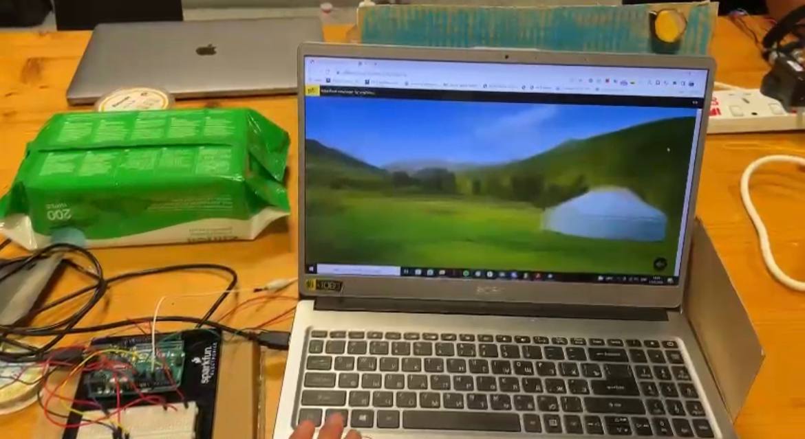
For this week, we focused on our visuals. We wanted to have our countries and videos. We ran into multiple problems where the video is not always triggered even though our code was the same. There was also the problem of having the video to stop looping go back to the original page (image of the map). So far we have gotten the Mexico video to work, but when we try to add the other videos, they do not work.
Here is our code:
const pts = []
var size = 0.6;
let alpha = 255;
let left = 0;
let right = 0;

let rVal0 = 0;
let rVal1 = 0;

let img1;
let vid0;
let vid1;


let playVid0 = false;
let playVid1 = false;

let playOnce0 = 0;
let playOnce1 = 0;

function preload () {
  img1 = loadImage("outline map.png");
}

function setup() {
  createCanvas(innerWidth, innerHeight);
  pixelDensity(5);
  textSize(18);
  setUpSerial();
  vid0 = createVideo("mexico.mp4")
  vid0.position(220, 100)
  vid0.size(560, 315);
  vid0.volume(1);
  vid0.hide();
  vid0.showControls();
  vid0.onended(sayDone);

  // vid1 = createVideo("Ethiopia.mp4")
  // vid1.position(220, 100)
  // vid1.size(800, 315);
  // vid1.volume(1);
  // vid1.hide();
  // vid1.showControls();
  // vid1.onended(sayDone);

}
function keyPressed() {
  if (key == " ") {
    // important to have in order to start the serial connection!!
    setUpSerial(SELECT_PORT);
  }
}
function draw() {
  console.log(rVal0)
  // console.log(rVal1)
  fill(100);
  stroke(255);
  strokeWeight(1);


  if (!serialActive) {
    text("Press Space Bar to select Serial Port", 20, 30);
  } else {
    text("Connected", 20, 30);
  }
  background(img1, 0, 0, innerWidth, innerHeight);


  if (playVid0 == true && playOnce0 == 0){
      vid0.show();
      vid0.loop();
      vid0.volume(1);
    }

    // if (playVid1 == true && playOnce1 == 0){
    //   vid1.show();
    //   vid1.loop();
    //   vid1.volume(1);
    // }
  }
  function sayDone(elt) {
    alert('done playing ' + elt.src);
    playOnce0 = 1;
    // playOnce1 = 1;
  }

function readSerial(data) {
  ////////////////////////////////////
  //READ FROM ARDUINO HERE
  ////////////////////////////////////

  if (data != null) {
    // make sure there is actually a message
    // split the message
    let fromArduino = split(trim(data), ",");
    // if the right length, then proceed
    if (fromArduino.length == 1) {
      // only store values here
      // do everything with those values in the main draw loop
    rVal0 = fromArduino[0];
      if (rVal0 > 100){
             playOnce0= 0;
             playVid0 = true;
        }
      //   rVal1 = fromArduino[1];
      // if (rVal1 > 100){
      //        playOnce1= 0;
      //        playVid1 = true;
      //   }
   }

    //////////////////////////////////
    //SEND TO ARDUINO HERE (handshake)
    //////////////////////////////////
    let sendToArduino = "\n";
    writeSerial(sendToArduino);
  }
}