Week 11 assignment – Tarek Nabih, Janindu Nanayakkara, Aadil Zakareya

Exercise 1:

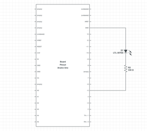
P5js code for exercise 1:

// variable to hold an instance of the p5.webserial library:
const serial = new p5.WebSerial();
 
// HTML button object:
let portButton;
let inData;                   // for incoming serial data
let outByte = 0;              // for outgoing data
 
function setup() {
  createCanvas(400, 300);          // make the canvas
  // check to see if serial is available:
  if (!navigator.serial) {
    alert("WebSerial is not supported in this browser. Try Chrome or MS Edge.");
  }
  // if serial is available, add connect/disconnect listeners:
  navigator.serial.addEventListener("connect", portConnect);
  navigator.serial.addEventListener("disconnect", portDisconnect);
  // check for any ports that are available:
  serial.getPorts();
  // if there's no port chosen, choose one:
  serial.on("noport", makePortButton);
  // open whatever port is available:
  serial.on("portavailable", openPort);
  // handle serial errors:
  serial.on("requesterror", portError);
  // handle any incoming serial data:
  serial.on("data", serialEvent);
  serial.on("close", makePortButton);
}
 
function draw() {
  
   background(0);
   fill(255);
   text("sensor value: " + inData, 30, 50);
 
}

// if there's no port selected, 
// make a port select button appear:
function makePortButton() {
  // create and position a port chooser button:
  portButton = createButton("choose port");
  portButton.position(10, 10);
  // give the port button a mousepressed handler:
  portButton.mousePressed(choosePort);
}
 
// make the port selector window appear:
function choosePort() {
  if (portButton) portButton.show();
  serial.requestPort();
}
 
// open the selected port, and make the port 
// button invisible:
function openPort() {
  // wait for the serial.open promise to return,
  // then call the initiateSerial function
  serial.open().then(initiateSerial);
 
  // once the port opens, let the user know:
  function initiateSerial() {
    console.log("port open");
  }
  // hide the port button once a port is chosen:
  if (portButton) portButton.hide();
}
 
// pop up an alert if there's a port error:
function portError(err) {
  alert("Serial port error: " + err);
}
// read any incoming data as a string
// (assumes a newline at the end of it):
function serialEvent() {
  inData = Number(serial.read());
  console.log(inData);
}
 
// try to connect if a new serial port 
// gets added (i.e. plugged in via USB):
function portConnect() {
  console.log("port connected");
  serial.getPorts();
}
 
// if a port is disconnected:
function portDisconnect() {
  serial.close();
  console.log("port disconnected");
}
 
function closePort() {
  serial.close();
}

Arduino code for exercise 1:

void setup() {
  Serial.begin(9600); // initialize serial communications
}
 
void loop() {
  // read the input pin:
  int potentiometer = analogRead(A0);                  
  // remap the pot value to fit in 1 byte:
  int mappedPot = map(potentiometer, 0, 1023, 0, 255); 
  // print it out the serial port:
  Serial.write(mappedPot);                             
  // slight delay to stabilize the ADC:
  delay(1);                                            
  
  // Delay so we only send 10 times per second and don't
  // flood the serial connection
  delay(100);
}

Demo:


Exercise 2:

P5js code:

let serial; // variable to hold an instance of the serialport library
let portName = "COM3"; // fill in your serial port name here
let xPos=0;
let yPos=240;
let onOff=0;
let val;
function setup() {
  createCanvas(640, 480);
  serial = new p5.SerialPort(); // make a new instance of the serialport library
  serial.on("list", printList); // set a callback function for the serialport list event
  serial.on("connected", serverConnected); // callback for connecting to the server
  serial.on("open", portOpen); // callback for the port opening
  serial.on("data", serialEvent); // callback for when new data arrives
  serial.on("error", serialError); // callback for errors
  serial.on("close", portClose); // callback for the port closing
  serial.list(); // list the serial ports
  serial.open(portName); // open a serial port
}
function draw() {
  background(255);
  val = map(mouseX, 0, width, 0, 255);
}
// get the list of ports:
function printList(portList) {
  // portList is an array of serial port names
  for (let i = 0; i < portList.length; i++) {
    // Display the list the console:
    print(i + " " + portList[i]);
  }
}
function serverConnected() {
  print("connected to server.");
}
function portOpen() {
  print("the serial port opened.");
}
function serialEvent() {
  // read a string from the serial port
  // until you get carriage return and newline:
  let inString = serial.readLine();
  serial.write(val);
}
function serialError(err) {
  print("Something went wrong with the serial port. " + err);
}
function portClose() {
  print("The serial port closed.");
}

Arduino code:

void setup() {
  Serial.begin(9600);
  pinMode(2, OUTPUT);
  pinMode(5, OUTPUT);
  while (Serial.available() <= 0) {
    Serial.println("0,0"); // send a starting message
    delay(200);      
  }
}
void loop() {
  while (Serial.available() > 0) {
    // read the incoming byte:
    int inByte = Serial.read();
    analogWrite(5,inByte);
    Serial.println();
  }
}


Exercise 3:

P5js code:

let serial; // variable to hold an instance of the serialport library
let portName = "COM7"; // fill in your serial port name here
let velocity;
let gravity;
let position;
let acceleration;
let wind;
let drag = 0.99;
let mass = 50;
let windVal;
function setup() {
  createCanvas(640, 360);
  noFill();
  position = createVector(width/2, 0);
  velocity = createVector(0,0);
  acceleration = createVector(0,0);
  gravity = createVector(0, 0.5*mass);
  wind = createVector(0,0);
  
  serial = new p5.SerialPort(); // make a new instance of the serialport library
  serial.on("list", printList); // set a callback function for the serialport list event
  serial.on("connected", serverConnected); // callback for connecting to the server
  serial.on("open", portOpen); // callback for the port opening
  serial.on("data", serialEvent); // callback for when new data arrives
  serial.on("error", serialError); // callback for errors
  serial.on("close", portClose); // callback for the port closing
  serial.list(); // list the serial ports
  serial.open(portName); // open a serial port
}
// get the list of ports:
function printList(portList) {
  // portList is an array of serial port names
  for (let i = 0; i < portList.length; i++) {
    // Display the list the console:
    print(i + " " + portList[i]);
  }
}
function serverConnected() {
  print("connected to server.");
}
function portOpen() {
  print("the serial port opened.");
}
function serialEvent() {
  // read a string from the serial port
  // until you get carriage return and newline:
  let inString = serial.readLine();
  print(inString);
  if (inString.length > 0){
    windVal = map(inString, 0, 1023, -3, 3);
  }
}
function serialError(err) {
  print("Something went wrong with the serial port. " + err);
}
function portClose() {
  print("The serial port closed.");
}
function draw() {
  background(255);
  
  wind.x = windVal;
  
  applyForce(wind);
  applyForce(gravity);
  velocity.add(acceleration);
  velocity.mult(drag);
  position.add(velocity);
  acceleration.mult(0);
  ellipse(position.x,position.y,mass,mass);
  
  if (position.y > height-mass/2 - 25){
    serial.write(255);
  }
  else serial.write(0);
  
  if (position.y > height-mass/2) {
      velocity.y *= -0.9;  // A little dampening when hitting the bottom
      position.y = height-mass/2;
    }
}
function applyForce(force){
  // Newton's 2nd law: F = M * A
  // or A = F / M
  let f = p5.Vector.div(force, mass);
  acceleration.add(f);
}
function keyPressed(){
  if (keyCode==LEFT_ARROW){
    wind.x=-1;
  } 
  if (keyCode==RIGHT_ARROW){
    wind.x=1;
  }
  if (key==' '){
    mass=random(15,80);
    position.x=width/2;
    position.y=-mass;
    velocity.mult(0);
  }
}

Arduino Code:

Arduino code
void setup() {
  Serial.begin(9600);
  pinMode(2, OUTPUT);
  while (Serial.available() <= 0) {
    Serial.println("0"); // send a starting message
    delay(300);              // wait 1/3 second
  }
}
void loop() {
  while (Serial.available() > 0) {
    // read the incoming byte:
    int inByte = Serial.read();
    analogWrite(2, inByte);
    int WindPower = analogRead(A0);
    Serial.println(WindPower);
    
  }
}


Assignment 11- Serial Communication

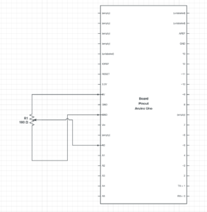
For the first-in-class exercise, we attached a potentiometer to the breadboard and connected Arduino to the P5js sketch. As we adjusted the serial input value of the potentiometer the ellipse moved up and down. We replaced the y coordinate of the ellipse with the incoming serial value to do so.

Here is the link to the video.

Code

P5js

// variable to hold an instance of the p5.webserial library:
const serial = new p5.WebSerial();
 
// HTML button object:
let portButton;
let inData;
// for incoming serial data
let outByte = 0;              // for outgoing data
 
function setup() {
  createCanvas(400, 300);          // make the canvas
  // check to see if serial is available:
  if (!navigator.serial) {
    alert("WebSerial is not supported in this browser. Try Chrome or MS Edge.");
  }
  // if serial is available, add connect/disconnect listeners:
  navigator.serial.addEventListener("connect", portConnect);
  navigator.serial.addEventListener("disconnect", portDisconnect);
  // check for any ports that are available:
  serial.getPorts();
  // if there's no port chosen, choose one:
  serial.on("noport", makePortButton);
  // open whatever port is available:
  serial.on("portavailable", openPort);
  // handle serial errors:
  serial.on("requesterror", portError);
  // handle any incoming serial data:
  serial.on("data", serialEvent);
  serial.on("close", makePortButton);
}
 
function draw() {
  
   background(0);
   fill(255);
   text("sensor value: " + inData, 30, 50);
  ellipse (200, inData, 50, 50)
  
}
// if there's no port selected, 
// make a port select button appear:
function makePortButton() {
  // create and position a port chooser button:
  portButton = createButton("choose port");
  portButton.position(10, 10);
  // give the port button a mousepressed handler:
  portButton.mousePressed(choosePort);
}
 
// make the port selector window appear:
function choosePort() {
  if (portButton) portButton.show();
  serial.requestPort();
}
 
// open the selected port, and make the port 
// button invisible:
function openPort() {
  // wait for the serial.open promise to return,
  // then call the initiateSerial function
  serial.open().then(initiateSerial);
 
  // once the port opens, let the user know:
  function initiateSerial() {
    console.log("port open");
  }
  // hide the port button once a port is chosen:
  if (portButton) portButton.hide();
}
 
// pop up an alert if there's a port error:
function portError(err) {
  alert("Serial port error: " + err);
}
// read any incoming data as a string
// (assumes a newline at the end of it):
function serialEvent() {
  inData = Number(serial.read());
  console.log();
  
}
 
// try to connect if a new serial port 
// gets added (i.e. plugged in via USB):
function portConnect() {
  console.log("port connected");
  serial.getPorts();
}
 
// if a port is disconnected:
function portDisconnect() {
  serial.close();
  console.log("port disconnected");
}
 
function closePort() {
  serial.close();
}

Arduino Code

void setup() {
  Serial.begin(9600); // initialize serial communications
}
 
void loop() {
  // read the input pin:
  int potentiometer = analogRead(A0);            
  // remap the pot value to fit in 1 byte:
  int mappedPot = map(potentiometer, 0, 1023, 0, 255); 
  // print it out the serial port:
  Serial.write(mappedPot); 
    // slight delay to stabilize the ADC:
  delay(1);                                                          
                                      
  
  // Delay so we only send 10 times per second and don't
  // flood the serial connection
  delay(100);
}


Final Project Proposal

By: Fuad & Phoebe

INSPIRATION

For our final project, we were interested in making another game, but instead of a more action-based game, one that was a subtle, calming, yet visually pleasing game. We discussed the mobile game I Love Hue, which is a puzzle type game that tasks the player with organizing a grid of tiles of different colors into a gradient. We also discussed the meaning of good interaction design and how to create a system whose parts were meaningful, intentional, and effective.  Something that was simple, with few “gadgets,” and minimalistic but visually pleasing animations were two things we wanted to incorporate. As such, we came up with a “color matching” game.

CONCEPT

Our color matching game consists of a series of “levels”, where each level displays a two squares side by, one square being the “target” color, and the other being the “test” square that the player must manipulate to match the target color. The player will be able to manipulate the color of the square by turning potentiometers on the Arduino board, each that correspond with the red, green, and blue values of the target color. The player will have a set amount of time to adjust the color of the test square and is scored based on how close the match is to the target color.

What Arduino will do 

As mentioned above, Arduino will provide the means for manipulating the color onscreen. Each potentiometer will be mapped to a value of 0 to 255, corresponding to RGB values. Other than perhaps clicking a key to start the game, the player shouldn’t need to use the keyboard or mouse.

What p5.js will do 

The sketch will provide almost all visuals of the game. However, we thought it would be interesting to include red, green, and blue LED’s on our board, whose brightness would change according to how close the user was to the values of the target color. Hence, the sketch would also communicate back to Arduino, adjusting the brightness of the LED’s.

Final Project Concept

Concept

For this project, I would like to make a drawing platform, in which as the user moves the pen connected to the device, the drawing appears on the p5js. To make the drawing more interesting and unique, I am going to add Perlin noise to the lines. Shown below is the rough diagram of the platform.

The device will consist of 2 arms (blue and orange), 2 joints (with potentiometers (green)), and a pen. Joint at the top is a fixed point so position of the arms will vary depending on the movement of the pen. Each joint is connected to a potentiometer in order to read the angle value. Since we will know the length of each arm and the angle between each arm, we will able to convert the values (polar) into a cartesian value that is easy to display on p5js.

For Perlin noise, I will simply add or substract random integers from the calculated points.

Interaction Between Arduino and P5JS

  1. Arduino reads potentiometer value
  2. Arduino sends sensor values to p5js
  3. P5js converts sensor values into cartesian coordinates
  4. P5js draws points on the canvas with some Perlin noise

I am very excited to work on this project, but I am worried about how smooth potentiometer will rotate, which may make moving a pen hard.

final project proposal

By: Fuad & Phoebe

INSPIRATION

For our final project, we were interested in making another game, but instead of a more action-based game, one that was a subtle, calming, yet visually pleasing game. We discussed the mobile game I Love Hue, which is a puzzle type game that tasks the player with organizing a grid of tiles of different colors into a gradient. We also discussed the meaning of good interaction design and how to create a system whose parts were meaningful, intentional, and effective.  Something that was simple, with few “gadgets,” and minimalistic but visually pleasing animations were two things we wanted to incorporate. As such, we came up with a “color matching” game.

CONCEPT 

Our color matching game consists of a series of “levels”, where each level displays a two squares side by, one square being the “target” color, and the other being the “test” square that the player must manipulate to match the target color. The player will be able to manipulate the color of the square by turning potentiometers on the Arduino board, each that correspond with the red, green, and blue values of the target color. The player will have a set amount of time to adjust the color of the test square and is scored based on how close the match is to the target color.


What Arduino will do 

As mentioned above, Arduino will provide the means for manipulating the color onscreen. Each potentiometer will be mapped to a value of 0 to 255, corresponding to rgb values. Other than perhaps clicking a key to start the game, the player shouldn’t need to use the keyboard or mouse.

What p5.js will do 

The sketch will provide almost all visuals of the game. However, we thought it would be interesting to include red, green, and blue LED’s on our board, whose brgithness would change according to how close the user was to the values of the target color. Hence, the sketch would also coommunicate back to Arduino, adjusting the brightness of the LED’s.

Week 11: Serial Communication Exercises

Exercise 1

Extending the potentiometer example demoed in class, we created a smiley ball that bounces horizontally across the screen whose velocity was dependent on the value of the potentiometer. Inside our Arduino code, we write the value of the potentiometer as serial output to the p5.js sketch: 

void loop() {
// put your main code here, to run repeatedly:
 int potentiomenter = analogRead(A0); 
 int mappedPot = map(potentiomenter, 0, 1023, 0, 255); 
 Serial.write(mappedPot); 
delay(100);

The corresponding breadboard is shown below: 

[image]

Inside our p5.js sketch, we created our smiley ball by making a simple Circle class with an x and y position and a move() method. The move method() doesn’t change the ball’s y position, as it remains constant along the horizontal axis height/2, but it does update the x position, which is calculated using the variable inData – the value of the potentiometer read from Arduino. A snipped of the code is shown below: 

class Circle {
constructor(x, y, d) {
this.x = x;
this.y = y;
this.d = d;
}
move() {
if (this.x<=50) {x = 1;}
else if (this.x>=550) {x =-1;}


let y;


if (inData==undefined) {
y=0;
} else {
y = inData;
}


this.x+=(y/20)*x;
}

Finally, a demo of the final product is shown below: 

Exercise 2

We thought that the first exercise was rather bland in terms of visuals, so for this exercise we wanted our p5.js sketch to be more interesting. We made the connection of a sun rising and falling to the brightness of an LED, hence our sketch shows a sun against a mountain landscape that can “rise” and “fall” by pushing the up and down arrow keys. As the sun “rises”, the sky changes to a bright magenta color, and when the sun “falls”, the sky deepens to a dark blue color. We achieved this by having the sun’s y position (also built from the Circle class of Exercise 1) determined the rgb values of the background, as demonstrated in the following code: 

function draw() {
background(300-c.y, 100-c.y, 100+c.y);
c.display();
c.move();


var rightBrightness = map(c.y, height, 0, 0, 255);

outData = rightBrightness; // setup the serial output
serial.write(outData); // write to serial for Arduino to pickup

This seamless gradient effect then corresponds to the brightness of an LED on our Arduino board. 

[image]

The sun’s y position is stored as outData, which is then sent to Arduino. Inside our Arduino code, we map the incoming value to a scale of 0 to 255 and use that value to analog write the LED brightness. A snippet of this code is shown below: 

void loop() {
if (Serial.available() > 0) { // see if there's incoming serial data
incomingByte = Serial.read(); // read it
led2brightness = map(incomingByte, 0, 255, 0, 255); // map the input value to the brightness for second LED
} else { }
analogWrite(ledPin, led2brightness); // write the brightness to the led pin 2


}

Finally, a demo of the finished product is shown below:

Exercise 3 

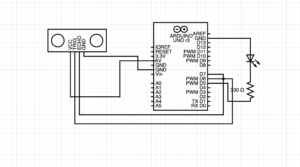
For the final exercise, we had to use bidirectional serial communication, which basically involved controlling a p5js sketch with an Arduino and tweaking the p5js sketch to affect the arduino. On the arduino, we used a distance sensor to affect the change of wind in p5js to make the ball move. Depending on the ball’s velocity, we programmed the p5js sketch so that an LED will turn on each time the ball bounces.

if (pos.y > height-mass/2) {
    velocity.y *= -0.9;  // A little dampening when hitting the bottom
    pos.y = height-mass/2;
    bounces+=1; 
    outData = "H"; 
    serial.write(outData); 
    console.log(outData); 
  }

The corresponding breadboard is shown below: 

[image]

Every time the ball strikes the platform, which occurs with the increment of the bounce counter, the program inside the p5js sketch sends “H” signals to the arduino. The Arduino then receives the H signals and activates the LED. The duration and distance variables in our Arduino code return the sound wave travel time in microseconds and the distance is the duration divided by two, respectively. The distance is next transmitted to the p5js sketch, which receives it as “indata” in p5js. A portion of the code is displayed below: 

void loop() {
  if (Serial.available() > 0) { // see if there's incoming serial data
    incomingByte = Serial.read(); // read it
    //Serial.println(incomingByte); 
    if (incomingByte == 'H') {    // if it's a capital H (ASCII 72),
      digitalWrite(LED, HIGH); // turn on the LED
      delay(100); 
      digitalWrite(LED, LOW); 
    }
  }
  //Clears the trigPin condition
  digitalWrite(trigPin, LOW);
  delayMicroseconds(2);
  // Sets the trigPin HIGH (ACTIVE) for 10 microseconds
  digitalWrite(trigPin, HIGH);
  delayMicroseconds(10);
  digitalWrite(trigPin, LOW);
  // Reads the echoPin, returns the sound wave travel time in microseconds
  duration = pulseIn(echoPin, HIGH);
  // Calculating the distance
  distance = duration * 0.034 / 2; // Speed of sound wave divided by 2 (go and back)
  // Displays the distance on the Serial Monitor
  Serial.write(distance); 
  //delay(1); 
}

Finally, a demo of the final product is shown below: 

(The images and videos of this post were lost with one of our colleagues phone that got damaged in water and never recovered.)

Pauline, Fuad, and Phoebe


Week 11: In-class Exercises

EXERCISE 1

Extending the potentiometer example demoed in class, we created a smiley ball that bounces horizontally across the screen whose velocity was dependent on the value of the potentiometer. Inside our Arduino code, we write the value of the potentiometer as serial output to the p5.js sketch:

void loop() {
// put your main code here, to run repeatedly:
int potentiomenter = analogRead(A0);
int mappedPot = map(potentiomenter, 0, 1023, 0, 255);
Serial.write(mappedPot);
delay(100);

The corresponding breadboard is shown below:

[image]

Inside our p5.js sketch, we created our smiley ball by making a simple Circle class with an x and y position and a move() method. The move method() doesn’t change the ball’s y position, as it remains constant along the horizontal axis height/2, but it does update the x position, which is calculated using the variable inData – the value of the potentiometer read from Arduino. A snipped of the code is shown below:

class Circle {
constructor(x, y, d) {
this.x = x;
this.y = y;
this.d = d;
}
move() {
if (this.x<=50) {x = 1;}
else if (this.x>=550) {x =-1;}


let y;


if (inData==undefined) {
y=0;
} else {
y = inData;
}


this.x+=(y/20)*x;
}

Finally, a demo of the final product is shown below:


EXCERCISE 2

We thought that the first exercise was rather bland in terms of visuals, so for this exercise we wanted our p5.js sketch to be more interesting. We made the connection of a sun rising and falling to the brightness of an LED, hence our sketch shows a sun against a mountain landscape that can “rise” and “fall” by pushing the up and down arrow keys. As the sun “rises”, the sky changes to a bright magenta color, and when the sun “falls”, the sky deepens to a dark blue color. We achieved this by having the sun’s y position (also built from the Circle class of Exercise 1) determine the rgb values of the background, as demonstrated in the following code:

function draw() {
background(300-c.y, 100-c.y, 100+c.y);
c.display();
c.move();


var rightBrightness = map(c.y, height, 0, 0, 255);


outData = rightBrightness; // setup the serial output
serial.write(outData); // write to serial for Arduino to pickup

This seamless gradient effect then corresponds to the brightness of an LED on our Arduino board.

[image]

The sun’s y position is stored as outData, which is then sent to Arduino. Inside our Arduino code, we map the incoming value to a scale of 0 to 255 and use that value to analog write the LED brightness. A snippet of this code is shown below:

void loop() {
if (Serial.available() > 0) { // see if there's incoming serial data
incomingByte = Serial.read(); // read it
led2brightness = map(incomingByte, 0, 255, 0, 255); // map the input value to the brightness for second LED
} else { }
analogWrite(ledPin, led2brightness); // write the brightness to the led pin 2


}

Finally, a demo of the finished product is shown below:


EXERCISE 3

For the final exercise we were required to incorporate bidirectional serial communication, basically using the arduino to control a p5js sketch, and using changes in the p5js sketch to produce changes to the arduino. On the arduino, we used a distance sensor to affect the change of wind in p5js to make the ball move. On the p5js sketch we programmed it in such a way that everytime the ball bounces an LED lights up depending on the velocity of the ball.

Final Project – Preliminary Idea

Concept

For the final project, I am still in the process of finalizing an option, but three of my initial ideas are the following: 

  1. Working on my midterm project
  2. Building a physical car that can be controlled using Arduino 
  3. A runner game where the character/ object needs to avoid obstacles 

Each of the ideas consists of two primary sections: p5.js and Arduino.

p5.js Component

For the first project, I will work to further improve the ‘chasing’ mechanism of the game. For the final project, once again, the system should be able to allow user to control the character using a keyboard/ mouse (initially). If I decide to go with this idea, I am planning on making infinite levels or lengths so that the user can interact with the game as long as they desire. 

Later, the idea of serial communication will be incorporated in order to allow a physical device to play the game. 

For the second project, I will have to work from scratch to develop a system that keeps track of user input from the keyboard or mouse, and then control the motion of the actual device. If I decide to build this device, I assume the p5.js task will be less compared to the physical computing work. Either way, I intend to build a car that interacts with the p5.js and lets the user control its motion. 


Arduino/ Physical Computing

For the first or the final project, the purpose of physical computing will be to facilitate the user to play the game without using their keyboard or mouse – in other words, it will use electrical components and sensors to record user input either in the form of digital or analog data. This data will alter some attributes of the game components as a result the game can be played using an Arduino component. 

The second option heavily relies on physical computing. The first job is to build a functional car. Then, it should be able to communicate with p5.js for control. Additionally, there could be a second physical device that could control the car instead of using the keyboard. 

The sensors and components that I may use are potentiometers, ultrasonic sound sensors, LEDs, photosensitive resistors (LDRs) as well as servo motors, wheels and DC batteries (for the second option). 

I will go with one idea, but I am concerned about the availability of additional sensors the second option may require. The coding part should not consume a lot of time, but the physical computing part may take a while. Either way, I look forward to developing a system that communicates with p5.js and Arduino to control an object or a character in the game environment. 

Serial Communication exercise

Control ellipse using potentiometer values:

This code is controlled by potentiometer values from Arduino, and these values are set to be X coordinate, which allows the ellipse to move whenever the potentiometer is changing its direction. The only drawback was the slow response of the program and the reading of the sensors.

Code:

// variable to hold an instance of the p5.webserial library:
const serial = new p5.WebSerial();
 
// HTML button object:
let portButton;
let inData;                   // for incoming serial data
let outByte = 0;              // for outgoing data
 
function setup() {
  createCanvas(400, 300);          // make the canvas
  // check to see if serial is available:
  if (!navigator.serial) {
    alert("WebSerial is not supported in this browser. Try Chrome or MS Edge.");
  }
  // if serial is available, add connect/disconnect listeners:
  navigator.serial.addEventListener("connect", portConnect);
  navigator.serial.addEventListener("disconnect", portDisconnect);
  // check for any ports that are available:
  serial.getPorts();
  // if there's no port chosen, choose one:
  serial.on("noport", makePortButton);
  // open whatever port is available:
  serial.on("portavailable", openPort);
  // handle serial errors:
  serial.on("requesterror", portError);
  // handle any incoming serial data:
  serial.on("data", serialEvent);
  serial.on("close", makePortButton);
}
 
function draw() {
  
   background(0);
   fill(255);
   //show the values
   text("sensor value: " + inData, 30, 50);
  
   //draw ellipse using those values
   ellipse(inData, height/2, 50,70);
 
}

// if there's no port selected, 
// make a port select button appear:
function makePortButton() {
  // create and position a port chooser button:
  portButton = createButton("choose port");
  portButton.position(10, 10);
  // give the port button a mousepressed handler:
  portButton.mousePressed(choosePort);
}
 
// make the port selector window appear:
function choosePort() {
  if (portButton) portButton.show();
  serial.requestPort();
}
 
// open the selected port, and make the port 
// button invisible:
function openPort() {
  // wait for the serial.open promise to return,
  // then call the initiateSerial function
  serial.open().then(initiateSerial);
 
  // once the port opens, let the user know:
  function initiateSerial() {
    console.log("port open");
  }
  // hide the port button once a port is chosen:
  if (portButton) portButton.hide();
}
 
// pop up an alert if there's a port error:
function portError(err) {
  alert("Serial port error: " + err);
}
// read any incoming data as a string
// (assumes a newline at the end of it):
function serialEvent() {
  inData = Number(serial.read());
  console.log(inData);
}
 
// try to connect if a new serial port 
// gets added (i.e. plugged in via USB):
function portConnect() {
  console.log("port connected");
  serial.getPorts();
}
 
// if a port is disconnected:
function portDisconnect() {
  serial.close();
  console.log("port disconnected");
}
 
function closePort() {
  serial.close();
}


Final Project Concept

Concept

For my final project, I would like to continue working on my jumping pony game concept by adding more features using Arduino.

The basic and simple idea and integration:

Use Arduino buttons to control the pony’s action->interaction from Arduino to p5js

When the pony jumps successfully turn the LED light on. Also, when the game ends, send an audio losing sound through the piezo buzzer->signal from p5js to Arduino.

The next step and more complex integration will be adding sensors to control the pony game. I am thinking of using a sound detection sensor, so when the user jumps, Arduino will detect the sound, and pony will jump together with the user.

The only challenge I am afraid of is the sensibility of the sensors, so it has to be really precise and there should not any delay in sending the sound signal to the game. As the game is fast-pacing, any delay will make the user experience dissatisfying.

If everything is gonna be successful, I believe this game can resemble the Xbox console concept and can be a fun cardio exercise 😆

Seven Xbox 360 Kinect Playing Tips and Tricks from the Number One #1 Kinect  Player in the World | BoZack's Blog