Final Project Proposal & Progress

Concept

For the final project, I plan to make a “Cyber-Pet”. I have always wanted a pet but my parents won’t let me, so I want to make one (or as close as it can get XD). This pet can get different emotions when the user interacts with it through typing in prompts. Its emotions are generated through services provided by OpenAI’s GPT 3.5 API. The emotions of the pet are scaled from 1 to 10, with 1 being very unhappy and 10 being very happy. When the pet gives back a response, the buzzer will run and make sounds. The angrier the pet is, the buzzer sounds will be higher pitched and more rapid. But if the pet is happy, the sounds will be more calm and pleasant (as pleasant as a buzzer can be). The pet will be equipped with 2 motors that allow the pet to move. It will also be equipped with a distance sensor. If the user inputs a certain command, it will trigger a condition. If the pet is happy, the pet will move towards the user as if looking for a hug. Otherwise, the pet will attempt to run away from the user while making loud noises with the buzzer.

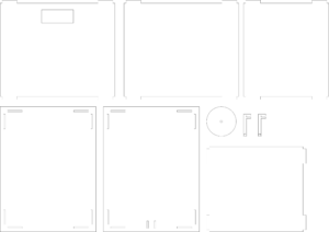
The Arduino board can be put inside a box made of wooden planks, and apart from the two back wheels driven by motors, it should also have another assistive wheel so that it can stand upright. The CAD drawing for the laser cutting of the board is shown below:

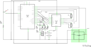
Below is the schematic for the Arduino board:

I will start cutting out the outer boards tomorrow, and then assemble and program the board.

Final Project – Draft 2 – Walking Buddy

Building on my initial idea to create an assistive device, I have decided to create a robot that serves as a walking assistant by warning the user of possible obstructions along the way. The robot would be voice controlled to give commands such as the direction of the robot. Based on the reading of an ultrasonic sensor the walking buddy would send out signals through the speaker to alert the user. Additionally, the user would be informed of the distance between the next obstruction to have a better sense while walking. If time permits, I plan to include the option of controlling the robot through hand movements as well to make the model more inclusive.

Arduino:

  • Uses the ultrasonic sensor to provide input on possible obstructions and sends it to p5.
  • Based on the ultrasonic reading the speaker plays a tune to warn the user.
  • The movement of the robot is controlled using the DC motors.

P5.js program:

  • Begins with informing the user of the different tunes and voice commands.
  • The user gives a voice command to change the direction of the robot.
  • The direction is communicated to the Arduino and the robot starts moving accordingly
  • P5 stores the distance from the next obstruction received from the Arduino and increases the frequency of the tune as the user gets closer to it.

Final Project: Something ml5.js

Progress:

As previously mentioned in my final project concept, I intend to create an “electronic buddy” or an “art robot” (which sounds better than my previous term). Thus far, I have successfully established communication between p5 and Arduino. Specifically, I utilized the handpose model from the ml5 library to detect if the hand is within specific areas on the screen and transmit a corresponding index to the Arduino.

As this is only a preliminary test, I have two motors connected to the Arduino, rotating in one direction if the hand is in the upper third of the screen, halting if the hand is in the middle portion, and rotating in the opposite direction if the hand is in the lower third. Currently, there is only unidirectional communication from p5 to Arduino, with p5 sending data to the latter. I hope to achieve meaningful communication from the Arduino to p5 as I progress. I have included the p5 sketch, Arduino sketch, and a video of the test run for reference.

p5 sketch:

let handpose;
let value = -1;
let video;
let predictions = [];

function setup() {
  createCanvas(640, 480);
  video = createCapture(VIDEO);
  video.size(width, height);

  handpose = ml5.handpose(video, modelReady);

  // This sets up an event that fills the global variable "predictions"
  // with an array every time new hand poses are detected
  handpose.on("predict", results => {
    predictions = results;
  });

  // Hide the video element, and just show the canvas
  video.hide();
}

function modelReady() {
  console.log("Model ready!");
}

function draw() {
  if (!serialActive) {
    text("Press Space Bar to select Serial Port", 20, 30);
  } else {
    image(video, 0, 0, width, height);

    // We can call both functions to draw all keypoints and the skeletons
    drawKeypoints();

    // draws sections on the screen
    for (let i = 0; i <= width / 2; i += (width / 2) / 3) {
      stroke(255, 0, 0);
      line(i , 0, i, height);
    }

    for (let i = 0; i <= height; i += height / 3) {
      stroke(255, 0, 0);
      line(0, i, width / 2, i);
    }

  }
  
}


function keyPressed() {
  if (key == " ") {
    // important to have in order to start the serial connection!!
    setUpSerial();
  }
}

function readSerial(data) {

  if (data != null) {

    //////////////////////////////////
    //SEND TO ARDUINO HERE (handshake)
    //////////////////////////////////
    let sendToArduino = value + "\n";
    writeSerial(sendToArduino);
  }
}

// A function to draw ellipses over the detected keypoints
function drawKeypoints() {
  for (let i = 0; i < predictions.length; i += 1) {
    const prediction = predictions[i];
    let area = [0, 0, 0, 0, 0, 0, 0, 0, 0];
    for (let j = 0; j < prediction.landmarks.length; j += 1) {
      const keypoint = prediction.landmarks[j];
      fill(0, 255, 0);
      noStroke();
      ellipse(keypoint[0], keypoint[1], 10, 10);
      
      // count number of trues
      // -- helps to detect the area the detected hand is in
      if (withinTopLeft(keypoint[0], keypoint[1])) {
        area[0] += 1;
      }
      if (withinTopCenter(keypoint[0], keypoint[1])) {
        area[1] += 1;
      }
      if (withinTopRight(keypoint[0], keypoint[1])) {
        area[2] += 1;
      }
      if (withinMiddleLeft(keypoint[0], keypoint[1])) {
        area[3] += 1;
      }
      if (withinMiddleCenter(keypoint[0], keypoint[1])) {
        area[4] += 1;
      }
      if (withinMiddleRight(keypoint[0], keypoint[1])) {
        area[5] += 1;
      }
      if (withinBottomLeft(keypoint[0], keypoint[1])) {
        area[6] += 1;
      }
      if (withinBottomCenter(keypoint[0], keypoint[1])) {
        area[7] += 1;
      }
      if (withinBottomRight(keypoint[0], keypoint[1])) {
        area[8] += 1;
      }
      // end of count
    }
    
    // print index
    for (let i = 0; i < area.length; i += 1) {
      if (area[i] == 21) {
        value = i;
      }
    }
  }
}

// returns true if a point is in a specific region
function withinTopLeft(x, y) {
  if (x >= 0 && x < (width / 2) / 3 && y >=0 && y < height / 3) {
    return true;
  }
  return false;
}

function withinTopCenter(x, y) {
  if (x > (width / 2) / 3  && x < 2 * (width / 2) / 3 && 
      y >=0 && y < height / 3) {
    return true;
  }
  return false;
}

function withinTopRight(x, y) {
  if (x > 2 * (width / 2) / 3 && x < (width / 2) && 
      y >=0 && y < height / 3) {
    return true;
  }
  return false;
}

function withinMiddleLeft(x, y) {
  if (x >= 0 && x < (width / 2) / 3 && y > height / 3 && y < 2 * height / 3) {
    return true;
  }
  return false;
}

function withinMiddleCenter(x, y) {
  if (x > (width / 2) / 3  && x < 2 * (width / 2) / 3 && 
      y > height / 3 && y < 2 * height / 3) {
    return true;
  }
  return false;
}

function withinMiddleRight(x, y) {
  if (x > 2 * (width / 2) / 3 && x < (width / 2) && 
      y > height / 3 && y < 2 * height / 3) {
    return true;
  }
  return false;
}

function withinBottomLeft(x, y) {
  if (x >= 0 && x < (width / 2) / 3 && y > 2 * height / 3 && y < height) {
    return true;
  }
  return false;
}

function withinBottomCenter(x, y) {
  if (x > (width / 2) / 3  && x < 2 * (width / 2) / 3 &&
      y > 2 * height / 3 && y < height) {
    return true;
  }
  return false;
}

function withinBottomRight(x, y) {
  if (x > 2 * (width / 2) / 3 && x < (width / 2) &&
      y > 2 * height / 3 && y < height) {
    return true;
  }
  return false;
}

Arduino sketch:

const int ain1Pin = 3;
const int ain2Pin = 4;
const int pwmAPin = 5;

const int bin1Pin = 8;
const int bin2Pin = 7;
const int pwmBPin = 6;


void setup() {
  // Start serial communication so we can send data
  // over the USB connection to our p5js sketch
  Serial.begin(9600);

  pinMode(LED_BUILTIN, OUTPUT);

  pinMode(ain1Pin, OUTPUT);
  pinMode(ain2Pin, OUTPUT);
  pinMode(pwmAPin, OUTPUT); // not needed really

  pinMode(bin1Pin, OUTPUT);
  pinMode(bin2Pin, OUTPUT);
  pinMode(pwmBPin, OUTPUT); // not needed really

  // TEST BEGIN
  // turn in one direction, full speed
  analogWrite(pwmAPin, 255);
  analogWrite(pwmBPin, 255);
  digitalWrite(ain1Pin, HIGH);
  digitalWrite(ain2Pin, LOW);
  digitalWrite(bin1Pin, HIGH);
  digitalWrite(bin2Pin, LOW);

  // stay here for a second
  delay(1000);

  // slow down
  int speed = 255;
  while (speed--) {
    analogWrite(pwmAPin, speed);
    analogWrite(pwmBPin, speed);
    delay(20);
  }

  // TEST END

  // start the handshake
  while (Serial.available() <= 0) {
    digitalWrite(LED_BUILTIN, HIGH); // on/blink while waiting for serial data
    Serial.println("0,0"); // send a starting message
    delay(300);            // wait 1/3 second
    digitalWrite(LED_BUILTIN, LOW);
    delay(50);
  }

}

void loop() {

  while (Serial.available()) {
    // sends dummy data to p5
    Serial.println("0,0");

    // led on while receiving data
    digitalWrite(LED_BUILTIN, HIGH); 

    // gets value from p5
    int value = Serial.parseInt();

    // changes brightness of the led
    if (Serial.read() == '\n') {
      
      if (value >= 0 && value <= 2) {
        digitalWrite(ain1Pin, HIGH);
        digitalWrite(ain2Pin, LOW);
        digitalWrite(bin1Pin, HIGH);
        digitalWrite(bin2Pin, LOW);

        analogWrite(pwmAPin, 255);
        analogWrite(pwmBPin, 255);

      }

      else if (value >= 3 && value <= 5) {
        analogWrite(pwmAPin, 0);
        analogWrite(pwmBPin, 0);
      }

      else {
        digitalWrite(ain1Pin, LOW);
        digitalWrite(ain2Pin, HIGH);
        digitalWrite(bin1Pin, LOW);
        digitalWrite(bin2Pin, HIGH);

        analogWrite(pwmAPin, 255);
        analogWrite(pwmBPin, 255);
      }
    }
  }
  // led off at end of reading
  digitalWrite(LED_BUILTIN, LOW);
}

Video:

Final Draft 1

Concept:

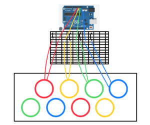
I’ve tentatively decided on a concept for my final project, though I’m not completely set on it yet. I’m considering creating a reaction time game centered around colors, featuring various levels of difficulty. The project involves a platform housing colored buttons capable of lighting up, with two buttons assigned to each of the four colors.

In the first level, a color will display on the screen, prompting the corresponding button to light up. Clicking that button reveals another color, illuminating the alternative button. The subsequent level increases the challenge by lighting up only one of the two buttons of the same color. For the third level, the screen will exhibit the name of the color in a different hue, requiring the player to press the button matching the displayed color rather than its name. This challenge can be reversed, prompting the player to press based on the text rather than the color, adding complexity to the game. a game will be around 10 lights color combination.

p5 interface

Regarding the interface, there will be a welcome screen on the p5 platform featuring a play button as well as an info button. After the player has read the instructions they click the play button. Clicking this will lead to a page displaying multiple levels for the user to select and start the game.

Components:

    • Arduino uno
    • 8 buttons
    • rigid body for the buttons
    • lots of jumper wirds

Arduino (Outgoing Data):

the ardunio would send feedback to p5 about the status of the buttons if pressed or not.

p5.js (Outgoing Commands):

during specific levels, the p5 will signal the Arduino to activate the light for the targeted button.

sketch:


Pet the Plant

Concept:
“Pet the Plant” is an interactive project that merges the physical and digital realms to provide users with the satisfaction of nurturing a virtual plant without the responsibilities and risks associated with real plants. Inspired by the creator’s struggles in maintaining live plants, the project employs Arduino and various sensors to simulate the physical actions of caring for a plant, while the digital aspect, coded in p5.js, reflects the plant’s growth.

Components:
1. Arduino Sensors:
– Potentiometer: Used to select from five different virtual plants.
– Force Resistor Sensor: Mimics soil patting motions by squeezing between fingers.
– Water Level Sensor: Allows users to virtually water the plant by pouring water into a cup.
– Photocell: Reads ambient “sunlight” affecting the virtual plant’s size and cloud visibility.

2. Digital Interface:
– Coded in C++ for Arduino and p5.js for the virtual experience.
– Utilizes p5.serialcontrol for communication between Arduino and p5.js.
– Screenshots in a GIF format showcase various scenes of the digital experience.

“Plant the Pet” Set-Up:
The physical interface is designed to align with the plant theme:
– Arduino and wires hidden inside a shoebox with a connecting hole to the laptop.
– Four holes on top for the sensors, placed inside small plant pots.
– Brown air-dry clay serves as simulated dirt, covered with fake grass to enhance the plant-like appearance.

Smart Plant Growth Monitor:
This project introduces a hands-on experience for users to monitor virtual plant growth on a computer screen. Key components include:
– Physical Soil Sensor: Arduino-powered soil moisture sensor.
– Digital Plant Simulation: Developed using P5.js for visual appeal.
– Real-time Data Exchange: Arduino collects and sends soil moisture data to the P5.js environment.
– User Interaction: Users physically water the virtual plant by adding water to the soil sensor.
– Feedback System: Visual feedback in the P5.js simulation reflects plant growth based on soil moisture levels.

Arduino & P5.js Outgoing Ongoing Data:
The Arduino collects real-time soil moisture data and transmits it to the P5.js environment. This ongoing data exchange facilitates a dynamic and responsive virtual plant simulation, allowing users to observe the impact of their actions on the plant’s growth in real-time. The interaction is designed to be user-friendly, creating an engaging and educational experience in the realm of virtual gardening.


Arduino Code

int pot; //potentiometer
int fsr; // force sensitive resistor
int humid; // humidity & temperature level sensor
int light; // photocell

void setup() {
  Serial.begin(9600);
}

void loop() {
  pot = analogRead(A0);
  fsr = analogRead(A1);
  humid = analogRead(A2);
  light = analogRead(A3);
  Serial.print(pot);
  Serial.print(',');
  Serial.print(fsr);
  Serial.print(',');
  Serial.print(humid);
  Serial.print(',');
  Serial.print(light);

}


Week 12 – Final Project Proposal

Concept

For my final project, I aim to create an engaging and personalized experience that will allow our students and workers to design their own NYUAD ID cards.

This project would address the issue of dissatisfaction with ID card photos. Individuals will be able to take their own photographs, through the feature of capturing their images in real-time.

Additionally, recognizing the importance of chosen names, I intend to include a space for users to input their preferred names, which will then appear on their ID cards.

To enhance individuality, the program will offer options to customize the photos with accessories like hats. People will also be able to choose their preferred animal to be displayed in the corner of the ID card.

This project seeks to not only address practical concerns but also provide a unique and enjoyable experience for users.

Design of the ID card (3 options) :
Production


  • P5 program will start with a display of a menu where people can read instructions and click “space” key to start the experience.
  • They will be presented with a live video so that participants can adjust their position and click enter to capture their selfie- photograph.
  • As soon as the photograph is captured the signal to Arduino is sent, so it can activate the buzzer. Arduino receives this as an output from the buzzer and activates a short sound that reminds one of the camera’s shot.
  • On the P5 sketch, the live video stops playing and participants are presented with the photograph.
  • Then participants can select their accessories as additional features for their ID card. This is done by sending communication from Arduino to P5(receiver).
  • When pressing the HAT button, which is a digital input on pin 2, participants will see an image of a hat. They can choose their hat by pressing the button again.
  • Then participants will need to adjust the position of a hat using 2 potentiometers or a joystick that also operates on 2 potentiometers (which are analog inputs and located on pins A0 and A1).
  • They can also do the same actions to choose their favorite animal by pressing the ANIMAL button. They can also select an appropriate location using a joystick or two potentiometers.
  • Participants will press ENTER to capture the new image with the chosen hat and animal, which then will be displayed on an ID card template on a P5 sketch.
  • Finally, participants can write their names on the ID card by inputting it in a given space.
  • By clicking the button “Finish” their final ID card will be printed and displayed as a small image on top of the menu screen.


Final Project Proposal: JJR (Jump Jump Revolution)

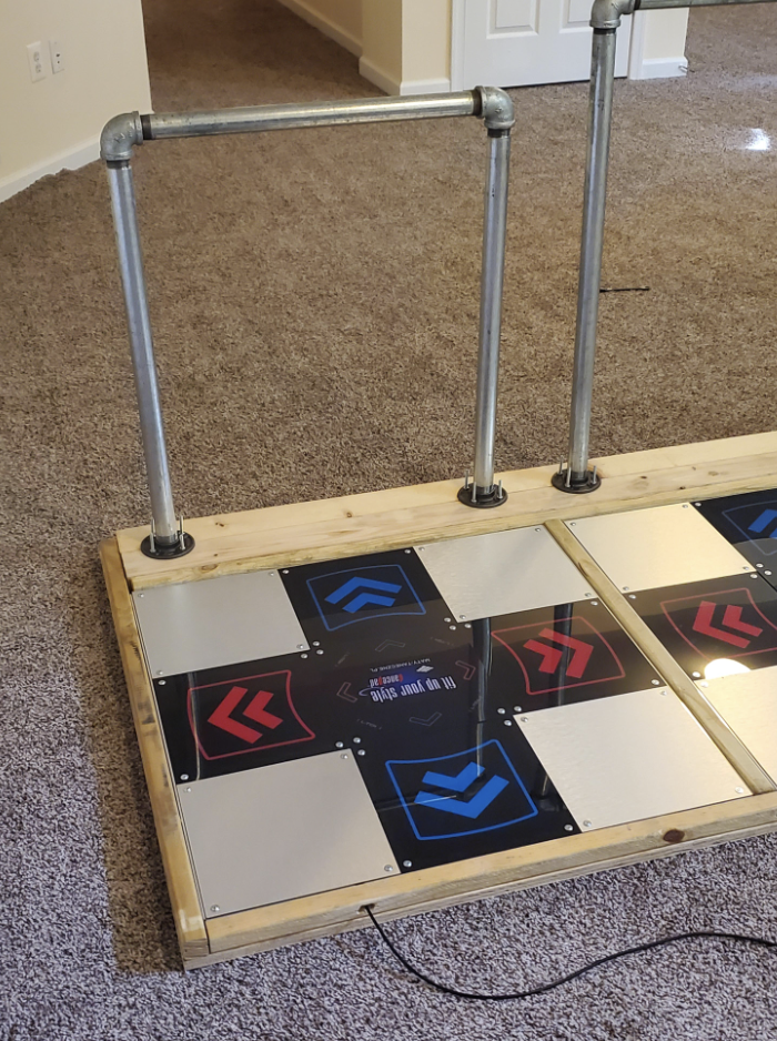
JJR (Jump Jump Revolution) is a remake of the famous video games series DDR (Dance Dance Revolution) but with a twist. This time, the user won’t dance on the platform, but will play a game instead. They won’t control a character in the game, they will be the character!

I want to create an interactive game utilizing a physical platform reminiscent of Dance Dance Revolution (DDR) for user control.

This project integrates Arduino for the physical interface and P5JS for the game itself. The user will navigate through the game by stepping on different tiles of a wooden platform, triggering corresponding actions in the game.

Disability Meets Design

Reflecting on the insights I gained from this reading, it is evident that achieving the right balance in designing for individuals with disabilities is crucial. Leckey’s approach to creating visually appealing furniture for kids with disabilities, without making it overly conspicuous, resonates as a prime example. The cautionary note about radios incorporating screens, hindering accessibility for visually impaired individuals, serves as a reminder that simplicity often triumphs in making things universally functional. Exploring multimodal interfaces, such as beeping buttons and flashing lights, emerges as a potential game-changer for those with sensory issues, providing diverse interaction avenues. The reading emphasizes the diversity among individuals, illustrated by the varying preferences of two people with visual impairments in their devices, debunking the notion of a one-size-fits-all solution. It prompts questions about the delicate balance designers must strike in making things accessible without introducing unnecessary complexity. Additionally, it raises inquiries about the role of designers in the accessibility landscape and underscores the importance of prosthetics aligning with both functionality and personal style. The reading broadens the perspective on design and accessibility, challenging conventional checkboxes and encouraging a more profound examination.

Pullin’s “Design Meets Disability” offers a comprehensive exploration of the intersection between disability, fashion, and design. Pullin adeptly goes beyond mere usability, delving into core concepts of inclusion and empowerment, particularly when viewed through the lenses of inclusivity and disability. The book showcases how assistive technology, such as glasses, hearing aids, and prosthetic limbs, has evolved into fashion statements, transforming basic needs into unique expressions of identity and personal style. Pullin emphasizes the significance of designs being both functional and aesthetically pleasing, challenging the perception that functionality must compromise visual appeal. This alignment of good design and utility has the potential to alter public perceptions of disability aids, fostering social acceptance and appreciation. The discussion highlights the importance of maintaining functionality without sacrificing simplicity, benefiting individuals with disabilities and contributing to universally usable designs that enhance overall quality of life. The reading underscores the need to pay meticulous attention to the preferences and needs of individuals with disabilities during the design process, challenging assumptions and societal stigmas. Ultimately, it encourages the creation of interactive designs that are not just functional but also user-friendly, simple, and fashionable, promoting inclusivity and thoughtfulness in the world.

Final Project Idea 2

Concept:

Create an automatic trash can that uses sensors to detect and sort different types of waste (plastic, paper, etc.) into separate compartments within the can. The system will utilize Arduino for hardware control and p5.js for a user interface to monitor and interact with the trash can.

Components:

  1. Arduino Uno
  2. Ultrasonic sensors or weight sensors to detect the type of waste being disposed of.
  3. Servo motors or stepper motors to control the compartments for different types of waste.
  4. P5.js for the user interface to monitor the trash can’s status and possibly interact with it.

Arduino (Outgoing Data):

Detecting and Sorting: Arduino reads sensor data to detect the type of material placed in the trash can. Based on this detection, it activates servo motors to sort the materials into their respective compartments.
Serial Communication: Once the material is detected and sorted, Arduino sends updates about the detected material type and sorting process status via the Serial connection.

p5.js (Outgoing Commands):

p5.js sends commands/instructions to the Arduino via the Serial connection, requesting the disposal of a particular type of waste.

Arduino (Incoming Commands):

Receiving Instructions: Arduino listens for incoming commands from p5.js through the Serial connection. It interprets these commands to initiate the disposal process.
Status Queries: Arduino responds to queries from p5.js by sending updates on the system status, like whether it’s ready to receive new commands or the current state of the sorting mechanism.

p5.js (Incoming Data):

Display and Feedback: p5.js receives data from Arduino about detected materials and system status.

Physical Computing’s Greatest Hits (and misses)

Considering the position of interactive artwork, this reading has prompted me to contemplate my perspective on interactivity. Tigoe’s perspective resonates with me, viewing interactive artworks as akin to performances. The artist constructs a stage for interactors, transforming them into the performers within this theatrical space.  Andrew Schneider’s piece, while appearing as a fixed narrative from a distance, offers diverse interactions in group settings, providing a more rewarding experience than a singular interpretation of museum paintings. Exploring the greatest hits and misses further complicates this perspective. Even seemingly straightforward interactions, like an LED lighting up upon approach, possess untapped potential for development. The originality of an idea lies not in the interaction itself but in the contextualization and open interpretation it offers. This nuanced approach to context and interpretation is particularly appealing. It leads me to contemplate the possibility of creating a more contextualized theremin, building on the potential for exploration within a defined setting.