Group: Dariga Shokayeva, Vladimir Sharkovski
Concept
We created a music instrument which plays beats. Our instrument is very versatile:
- The distance sensor allows you to easily control the frequency of the tone, without having to touch anything. Therefore you can play both very low tones and very high ones.
- The potentiometer allows you control the duration of the beats, from 20 milliseconds to half a second. Therefore you can play both a rapidfire almost continual beat, or a slow jazzy beat.
- The button allows you to shift the frequency of the tone to a higher range while the button is pressed. Therefore you can quickly surprise the listener with your melodies.
Video demo
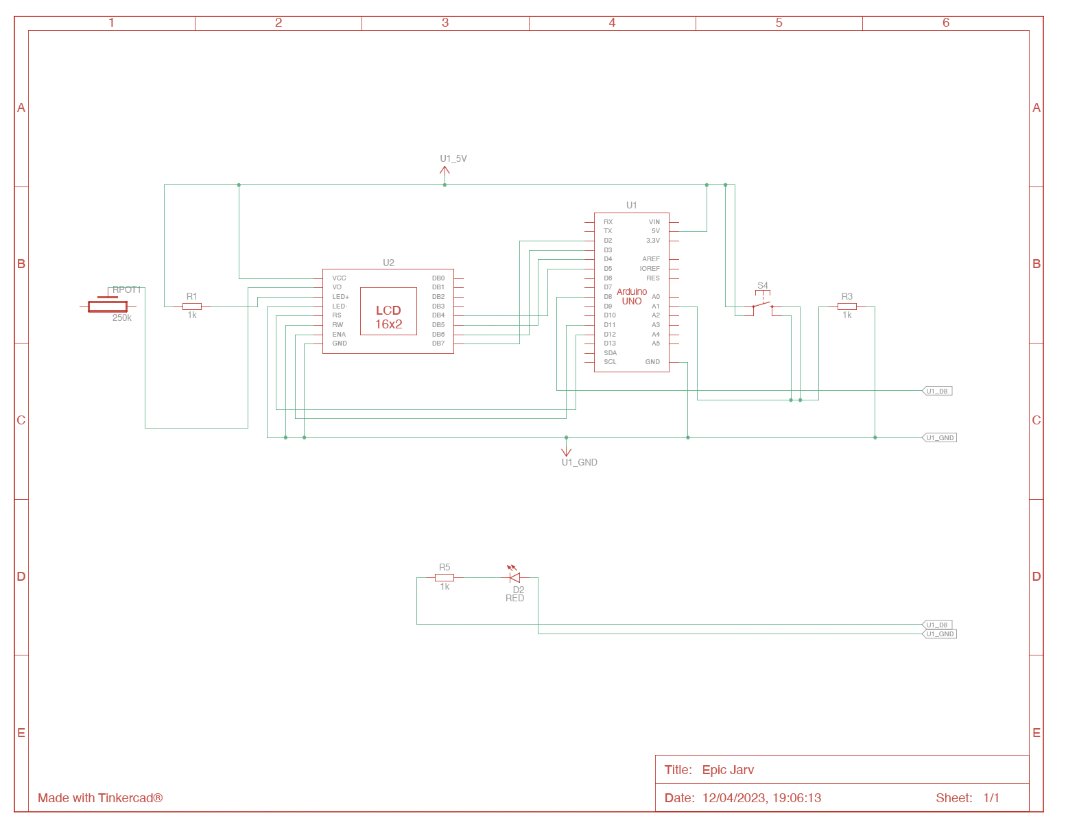
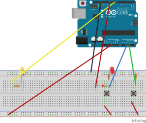
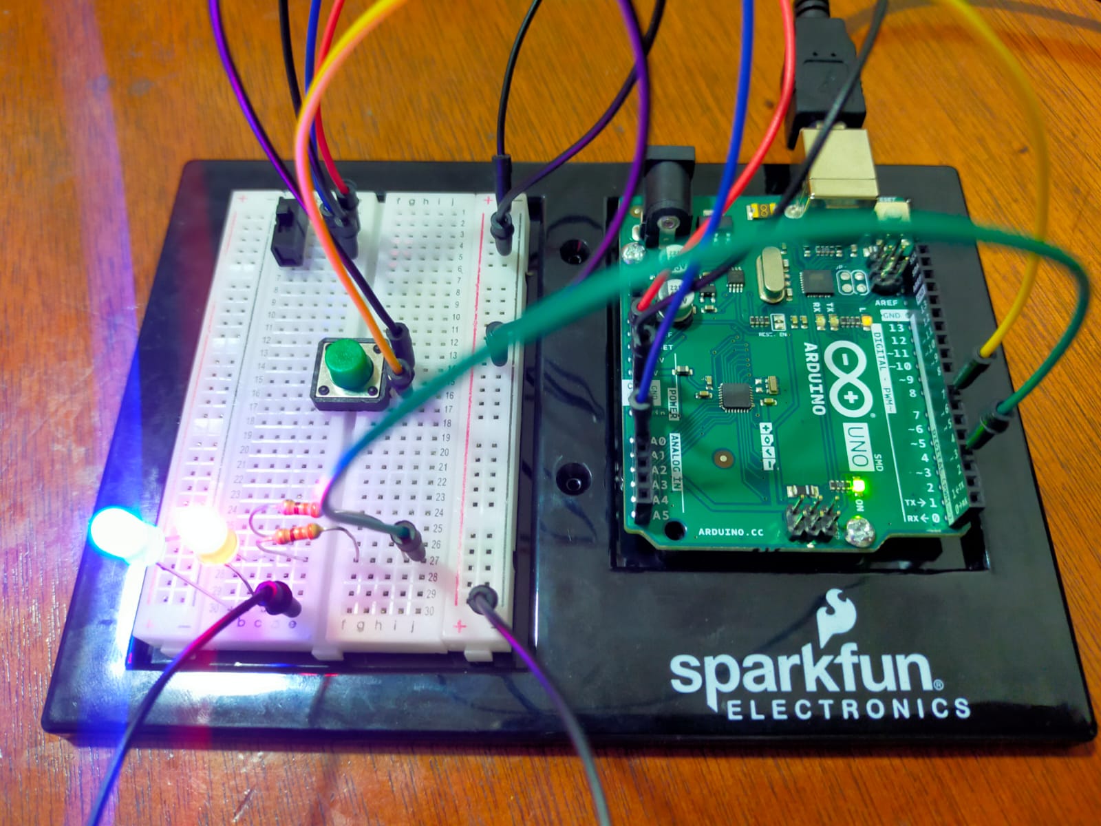
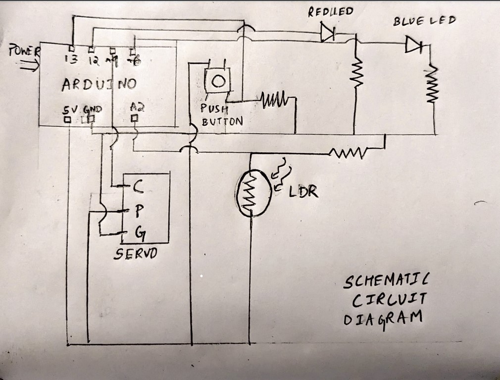
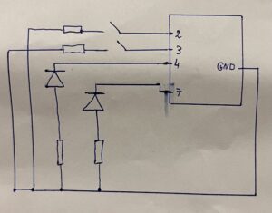
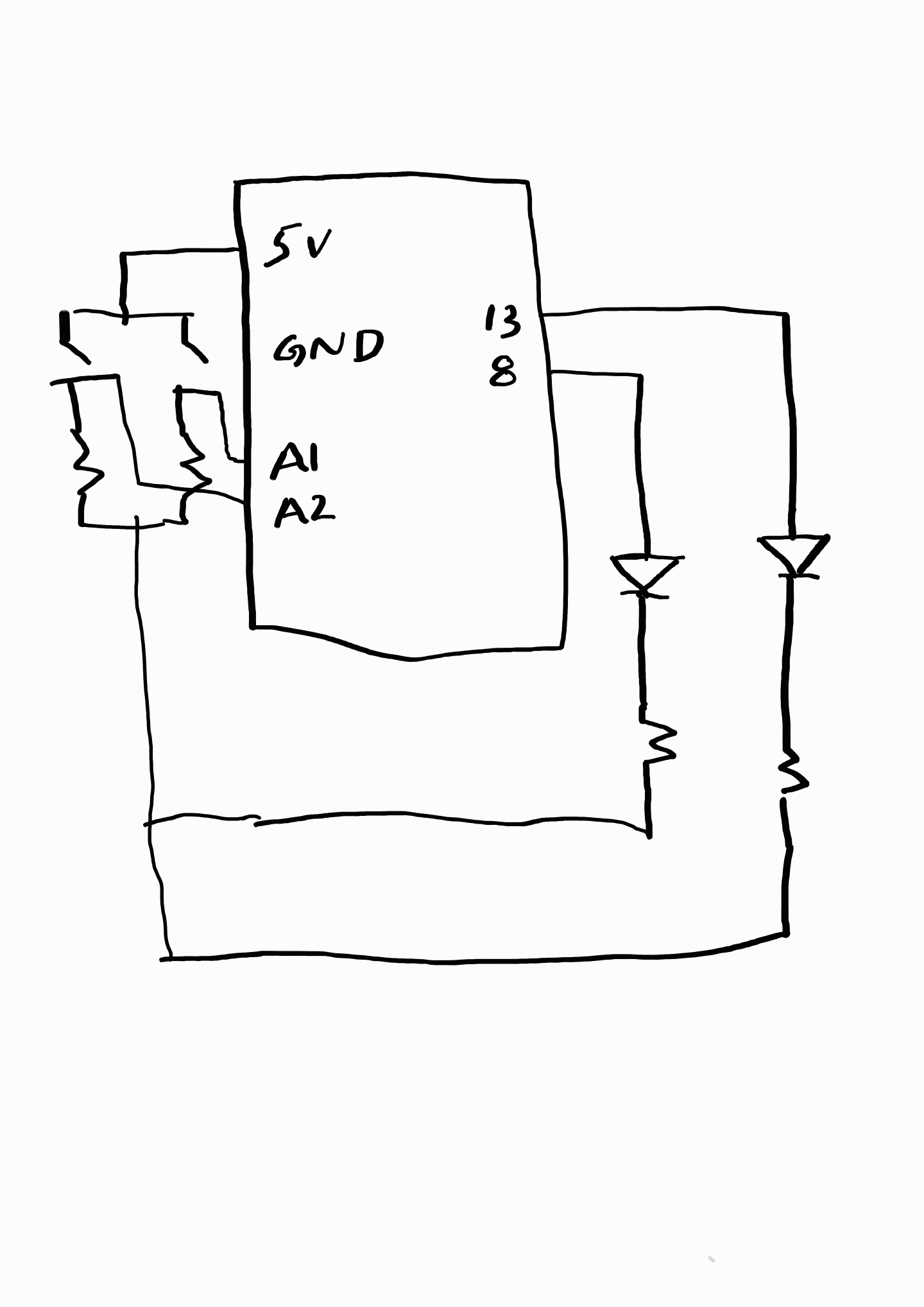
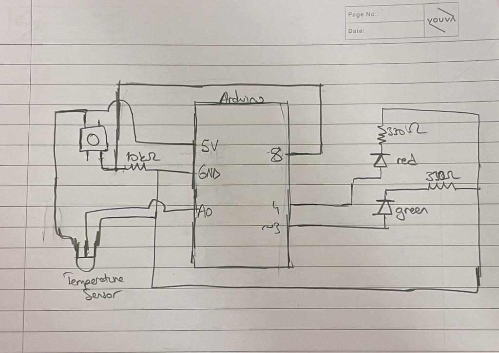
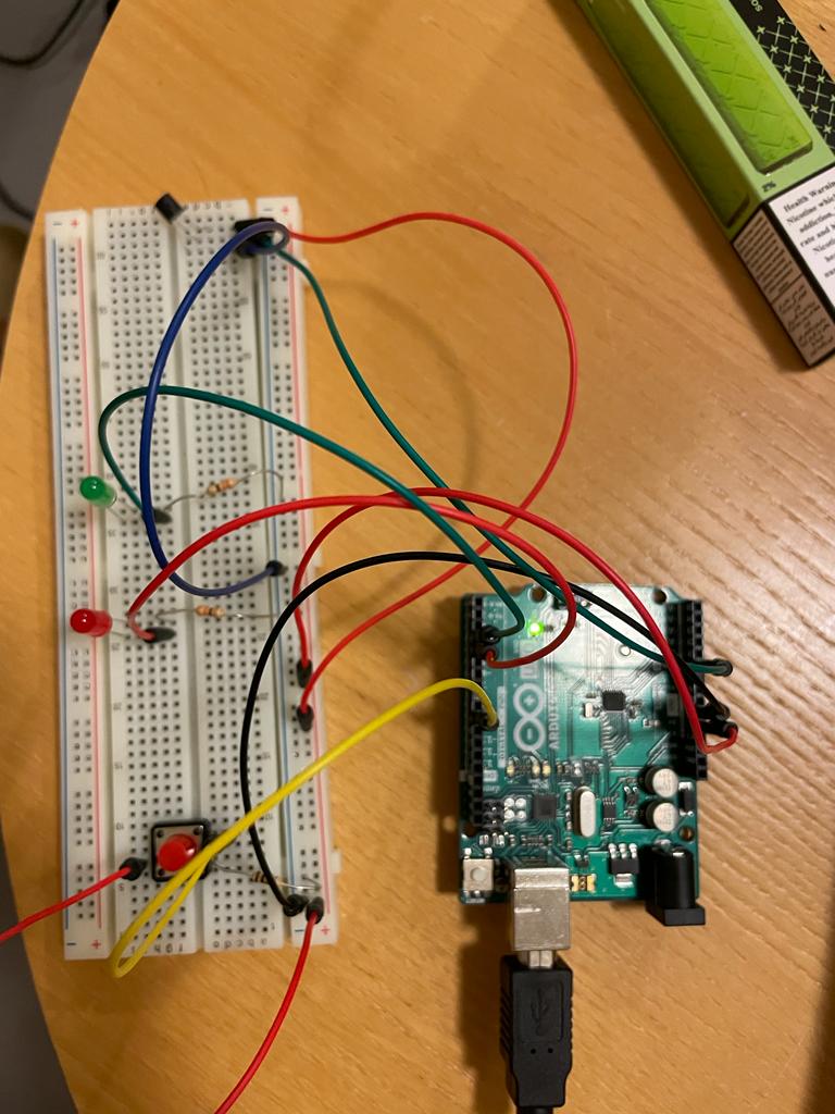
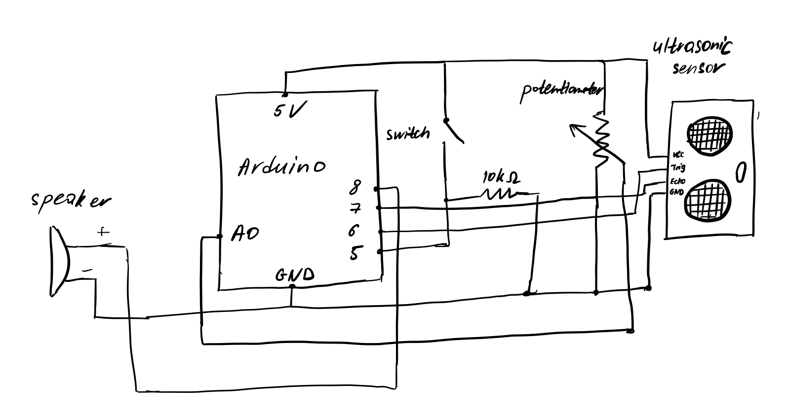
Circuit diagram
Code
// Pin positions.
const int potPin = A0;
const int buttonPin = 5;
const int trigPin = 6;
const int echoPin = 7;
const int speakerPin = 8;

// Other constants.
const int minDistance = 0;
const int maxDistance = 20;

const int toneDurationMin = 30;
const int toneDurationMax = 500;

const float toneDelayFactor = 1.3f;

void setup() {
  pinMode(potPin, INPUT);
  pinMode(buttonPin, INPUT);
  pinMode(trigPin, OUTPUT);
  pinMode(echoPin, INPUT);
  pinMode(speakerPin, OUTPUT);
}

long getSensorDistance() {
  // Send pulse.
  digitalWrite(trigPin, LOW);
  delayMicroseconds(2);
  digitalWrite(trigPin, HIGH);
  delayMicroseconds(10);
  digitalWrite(trigPin, LOW);
  // Read pulse duration.
  long duration = pulseIn(echoPin, HIGH);
  // Calculate distance from duration.
  long distance = (double)duration * 0.034 / 2.0;

  return distance;
}

void loop() {
  // Get distance and constrain it.
  long distance = getSensorDistance();
  distance = constrain(distance, minDistance, maxDistance);

  // Map distance to tone frequency.
  int toneFreqMin, toneFreqMax;
  int buttonState = digitalRead(buttonPin);

  if (buttonState == LOW) {
    toneFreqMin = 20;
    toneFreqMax = 400;
  } else {
    toneFreqMin = 300;
    toneFreqMax = 1500;
  }

  int toneFrequency = map(distance, minDistance, maxDistance, toneFreqMin, toneFreqMax);

  // Calculate time to play the tone based on the potentiometer position.
  int potPosition = analogRead(potPin);
  int toneDuration = map(potPosition, 0, 1023, toneDurationMin, toneDurationMax);

  // Play the tone, then wait some time.
  int waitTime = toneDuration * toneDelayFactor;
  tone(speakerPin, toneFrequency, toneDuration);
  delay(waitTime);
}
Reflection
It was challenging to figure out how the ultrasonic distance sensor worked, because it has 4 pins to set up. We also had to do some math, using the speed of sound, to convert the duration produced by the sensor into a proper distance.
Also, it took a lot of work to figure out the proper ranges for the minimum and maximum frequency for the instrument to play. Too high frequencies were irritating.
One way to improve the instrument is to think about ways to make it easier to use (more accessible). Right now it is a bit awkward to control the potentiometer and button with one hand, while using the other hand with the sensor. Also, it would be convenient to have a way to mute the speaker, or even control its volume.