Week 8 unusual switch

Concept

For my unusual switch, I had a pretty difficult time trying to come up with a creative method without using hands to make a switch. Initially I thought of some switch using a plastic water bottle and its cap, but then it struck me that water is also a conductor. So I came up with the idea to use water to turn the switch on.
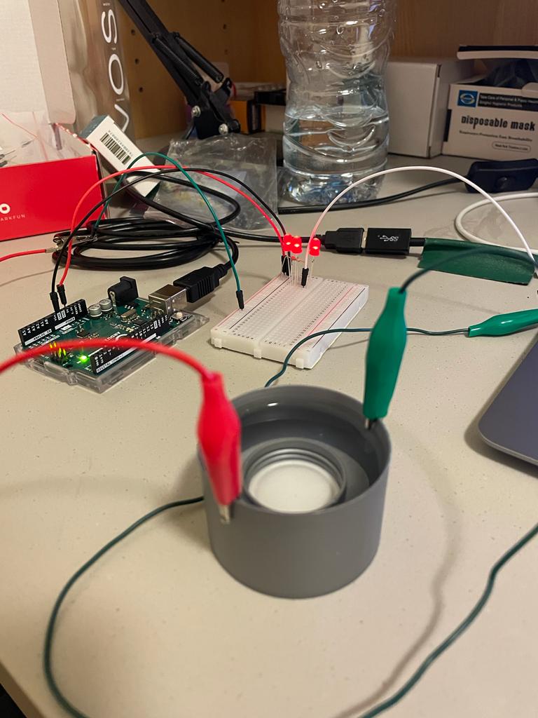
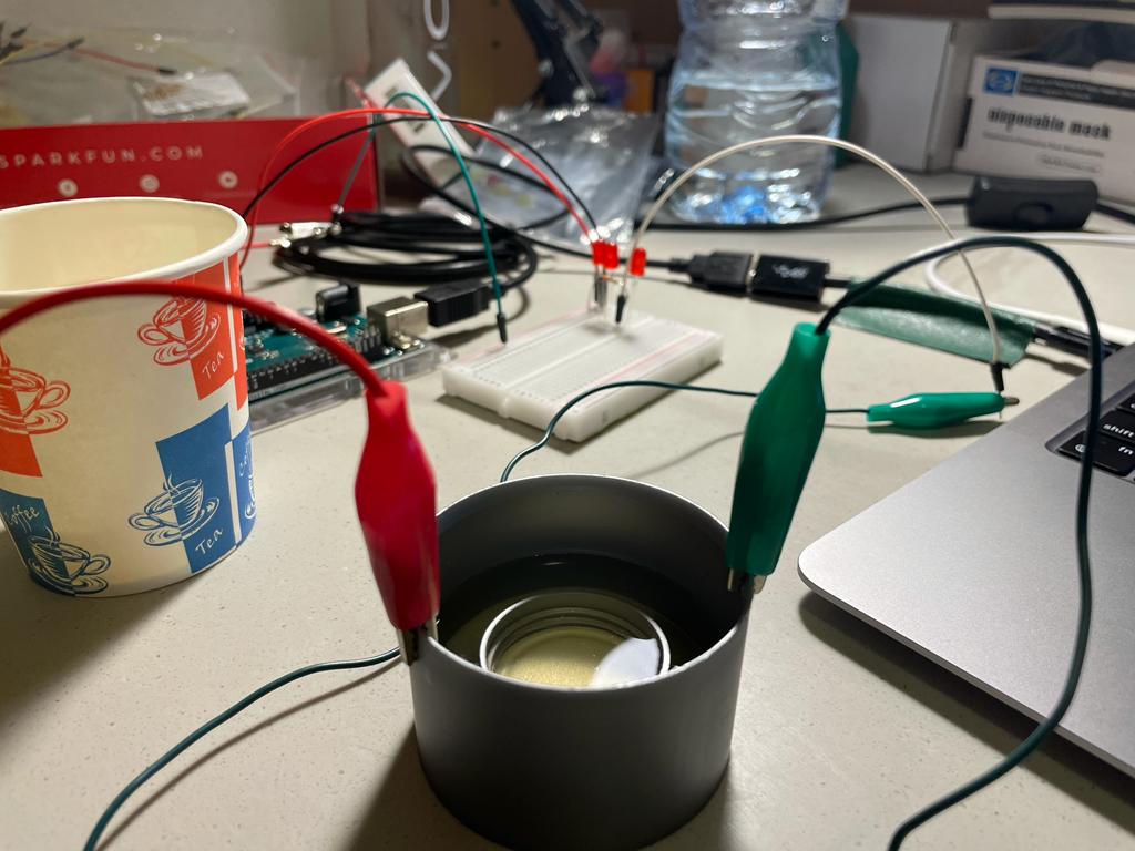
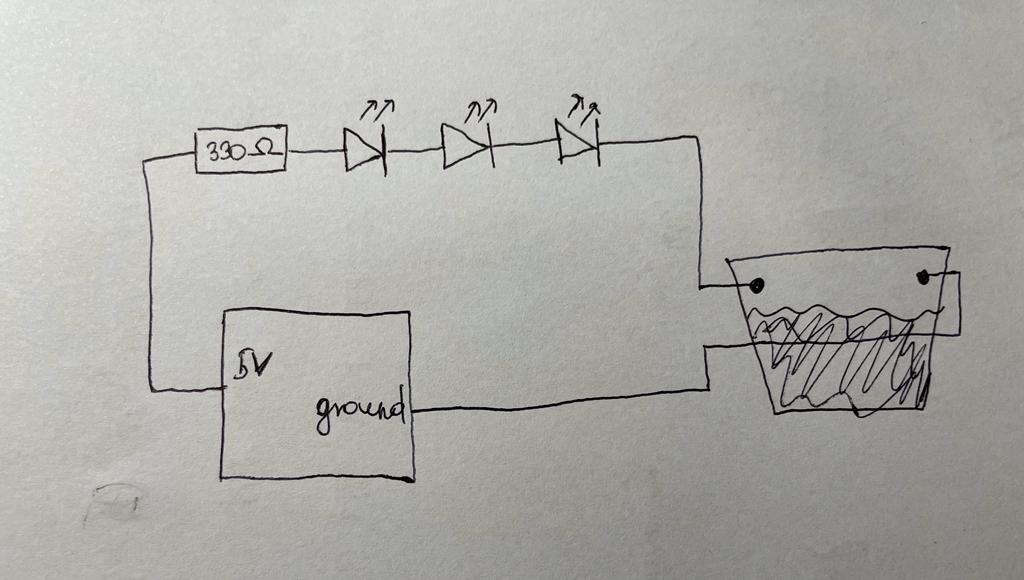
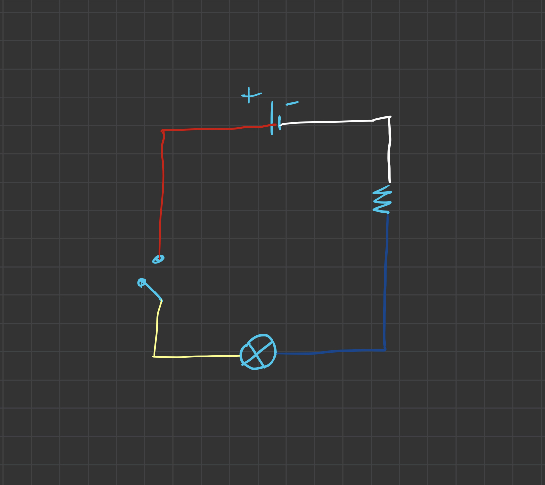
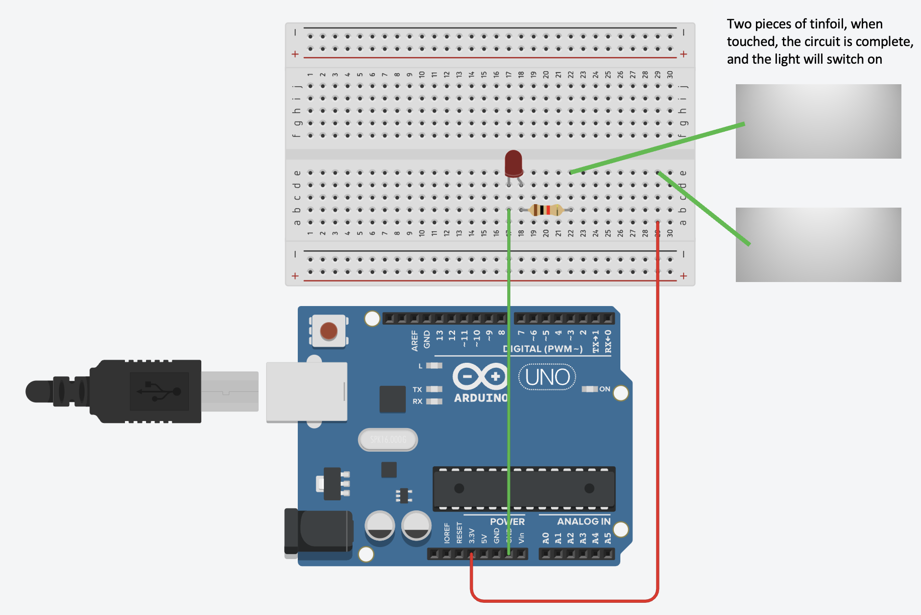
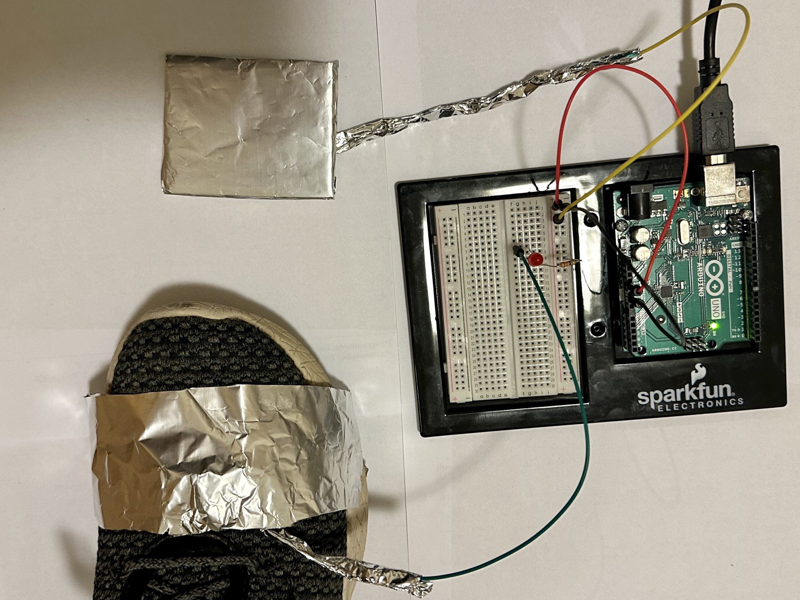
Methodology

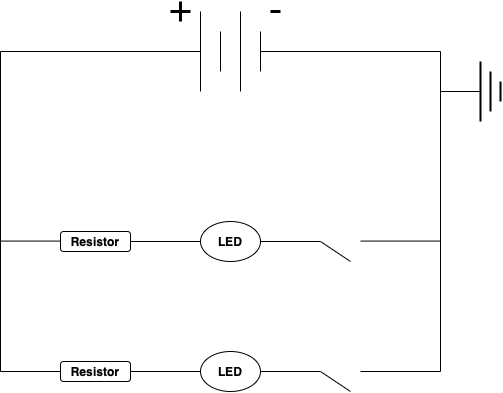
It’s is very very simple. I attached two ends of wire that is connected to a system inside a cup. All I have to do to turn the light on, is to pour water on the cup. If enough water is filled so that the surface of the water touches the wire ends, then electricity will flow through the water and complete the system. While doing this process I also found out the light produced from the bulb was a bit dimmer than using just the arduino board which meant some electricity flow of the system was lost due to the water’s resistance, which meant that water is not a good conductor. While I based this project on my vague memory of common sense that water is an electric conductor, apparently through a quick google search, apparently pure water is actually an insulator since it doesn’t contain any ions, but tap water is still a conductor because it contains some impurities.

Video

Future Improvements

As simple as this switch is, the downside of this switch is that it’s a bit bothersome to pour the water out to turn the light back off since there are wires attached to the cup and the arduino board. A simple fix to that is to put a straw in the cup and drink the water to turn the light off, but unfortunately I didn’t have any straws in my room nor I couldn’t think of this easy fix before I disassembled the entire switch… But I did learn something new about water today which is a bonus I didn’t think of.

Week 8 – Unusual Switch – Sea Level Detector

Concept

For this assignment I decided to create a potentially useful and practical switch that can be utilized in real world for detecting the sea level. My switch lights up with three red LEDs indicating that the water level at sea is above a certain point. Sea Level Detector does not use a traditional sensor. Instead, it relies on the conductivity of saltwater to complete the circuit and activate the LEDs.

This project is a great way to raise awareness about rising sea levels and the impact of climate change. By using simple materials and basic electronics, it is accessible to anyone interested in building their own Sea Level Detector. The project can also be modified to include additional features, such as data logging or remote monitoring, to make it even more useful and informative.

Implementation

The Sea Level Detector uses two metal rods, which are connected to the Arduino board and placed in the saltwater. As the water level rises, it comes into contact with both rods, completing the circuit and allowing electricity to flow between them. This results in the LEDs lighting up, indicating that the water level has reached a certain point.

The conductivity of saltwater is due to the presence of ions, specifically Na+ (sodium ions) and Cl- (chloride ions). These ions allow the water to conduct electricity, which is the principle behind the Sea Level Detector.


First picture depicts a high level of water which touches the metal rods conducting electricity through water lighting up the three red LEDs. In contrast, second picture shows the low level of water where rods are not in contact with water thus not conducting the electricity and LEDs are off.

Schematic Diagram

Video Demo


Assignment – Do Not Disturb (Unusual Switch)

Concept and Methods: 

In the past, I’ve spent a significant amount of time trying to use my card to open a locked room door. All that inspired me to create this circuit which indicates whether a door is locked from the inside using a simple LED circuit. I built it using the SparkFun inventor’s kit and some spare foil I had laying around. I realized my idea by putting two wires inside the lock hole in the door frame and having the lock itself act as a switch as it’s made from metal and it is conductive. I additionally wrapped the metal endings of the wires with tin foil to increase the surface area and ensure that the lock touches on both of them connecting the circuit.

Reflection 

This assignment was somewhat tricky to record as I was not able to record the exact switching on because it was going on inside the door frame. Additionally, I can improve this as it is visible in the video that the led flickers as the door unlocks which implies something loose in the setup. Beside these points, I think I executed this well as it works and that can be heard in the video. Finally, I had a bunch of fun putting this project together and I look forward to learning more about physical computing.

Assignment 6 – Creating an Unusual Switch

Concept

I decided to make my ring a little interactive with this project. Since the ring is made out of conductive material and it leaves just enough room for the two ends of the wires to fit in while it slides into my finger, I thought why not.  Plus, I wear the ring almost every day so using it in an unusual manner was fun. The following is a picture of the circuit diagram that I drew before building the switch to help me out:

Implementation

I started off by mapping the colors of the wires on my drawing to be exactly the ones I would be using in the real-life circuit (except the black one for earth which is white in the diagram). Next, I connected four 1.5V batteries that I had conveniently lying around in my drawer to the circuit board. I added a 330 ohm resistor and left two wires open to act as the switch (yellow and red). Next, the tricky part was to connect the ends of the wires to the ring. I used two small pieces of squash tape to get this done, I left one of the wires partially ‘hanging’ while still being tied to the ring so that the circuit completes only when I wear the ring and the end of the wire is pushed against the surface of the ring.

Week 8 – Unusual Switch

Idea

Since we are not allowed to use our hands to create a switch, the first thing I thought of was using my legs. I wanted to make something that is simple but also useful/could solve some real problem. One of the habits that I have is toe-tapping which I keep doing unconsciously when I sit in one place for a long time.  It’s hard to consciously be aware of this, so the things that easily draw attention, such as a continuously blinking light bulb, could help me and other people having the same problem be more aware of when they do toe-tapping and consequently eradicate this disturbing behavior.


How it works

My switch consists of a ring made of aluminum foil and a flat square cardboard covered with aluminum foil. You wear the aluminum ring to your shoes and place the square cardboard right underneath your legs. Every time you fidget and touch the cardboard with your legs the bulb lights up, signaling you that you’re doing toe-tapping.


Video


Future Improvements

This switch design is pretty simple and straightforward, however it is not very practical if I want to use it to detect and fight my fidget behavior. So one of the future improvements would be to make the design more user-friendly: I could work on expanding the wires so that the light bulb will be right in front of me, not on the ground, and I’ll be able to actually see it when working on a desk.

Unusual Switch – Yerkebulan Imanbayev

Idea:

For my unusual switch, I was inspired by Grinch and his signature furrowed eyebrows. Specifically, I decided to create my circuit in a way that grimacing (or furrowing your brows) is equal to the action of turning over the switch.

Execution:

I decided to create a simple circuit with a resistor and an LED. I have a wire that is connected to the power source and the LED. The LED is connected to a resistor, which, in turn, is connected to a wire. This wire is connected to a strip of aluminum foil, which is taped to one of my brows. I connected another wire to the ground and then taped aluminum foil on it as well, connecting it to my other brow. Now, if I furrow my eyebrows, the aluminum brows connect, conducting the electricity and turning the light bulb. If I do not make a Grinch face, the wires are disconnected, which does not conduct any electricity. Below, I created a simple diagram of the circuit:

Video:

HW5: Unusual Switch

CONCEPT

The inspiration for this assignment came from the treasure chests I have seen in cartoons as a child. The ones that glow and shine from inside when you open them. I made a box with a “hidden” breadboard that has LEDs on it that turn on when you open the lid of the box. I know that I don’t have the skills or the materials to make a realistic chest, so the vibe for this chest is DIY, something that a child would make to hide secret objects.

Treasure chest Vectors & Illustrations for Free Download | Freepik

IMPLEMENTATION

I used a popcorn box for a chest. Since the inside of the box is brown-grey and looks more like a chest I turned it inside out, and used some tape to put it back together. I then a hole at the bottom of the chest to hide the breadboard, one of the jumping wires on the breadboard, and the two jumping wires that connect to the Arduino. I made a small opening on the lid of the chest for one of the jumping wires to connect the circuit.

The circuit uses 5 LED lights, 5 330Ohm resistors, and 8 jumper cables. The LED lights are each connected to each other using 4 yellow jumper cables. One red jumper cable connects from positive on a breadboard to 5V on Arduino. A black jumper cable is used to connect from the negative on a breadboard to GND on Arduino. Blue (-) and green (LED) jumper cables need to connect to complete the circuit and light the LEDs. The blue cable is hidden under the box and attached by a piece of tape to the back of the box. A piece of foil is attached at the free end of the cable to make the connection area bigger. The free tip of the green cable sticks out of the lid of the box through a small opening. When the box is opened, the lid gets closer to the back of the box, making the green and blue cables touch.

To imitate a chest full of golden bits, I filled the box with ripped yellow paper and covered the breadboard for the most part. I have used yellow jumper cables for the cables that would stay fully inside the box to make them less visible.

schematic used

DEMO VIDEO

If the video window doesn’t show, use this link to see the demo of the treasure chest.

Assignment 5 – Creative Switch

The Concept

The idea was to create a switch the user can never see. I wanted to achieve this by allowing the circuit to complete only when the user closed their eyes. The second the eyes open, the switch opens and hence, the one controlling the switch can never know whether the switch actually ever made the light turn on or not.

The Circuit

I started by sketching out my circuit and then got to work on the bread board. The idea was to add the switch on the positive wire coming from the Arduino, so I got two pieces of aluminum to form the switch. Thus I attached the two pieces of aluminum on the connection between the arduino and the positive end of the LED. Then I attached those two pieces of aluminum to my eye lids, in a way that the switch closes when I close my eyes. This was a pretty challenging aspect as the jumper cables would weigh down the aluminum and the switch wouldn’t close properly. Eventually I ended up taping parts of the wire to my face and attaching the bread board itself to my face as well, so I can mitigate the gravity issue.


The Demo


Week 8 – Bicep Switch

This week’s assignment required us to design a straightforward circuit switch without the use of our hands. When thinking about how to remove the hands from creating a switch I thought of the area further up the arm which was the bicep and forearm. The switch turns on by flexing my bicep muscle and completing the circuit.

I began by building a basic circuit that would turn on the LED whenever the circuit was closed. Then I unplugged the ground from the main + and – bus on the breadboard and removed the power to the LED row. I decided to use aluminum foil, which functions as an electrical conductor, to complete the circuit and turn on the switch. The connection was then redirected onto a piece of aluminum foil using wires and a jumper to attach. I was able to close the circuit by securing the piece of aluminum foil to the top of my bicep and bottom of my forearm. This allowed me to complete the circuit by flexing my bicep which brought the 2 pieces of aluminum together and completed the circuit and turn on the LED.

Week 8: Unusual Switch

Concept

Since, we had to make a switch that did not require the use of hands, I thought of using wind to switch on the LED lights. The easiest thing to do was to blow onto a metallic strip like aluminium or tin foil, such that the strip would touch another metallic surface to complete the circuit.

This idea of blowing onto something let me develop this project into a device that would act as a spirometer (Fig. below). A spirometer is a device used to test a person’s lung capacity. One would simply blow onto the pipe and try to raise the three balls to the top. The idea of my switch is similar; one would simply blow onto two strips of metallic strip to turn on the two LED lights.

Video

How it Works

I used some copper tapes and joined them together to make two flexible metallic strip. I used a solid metallic sheets such that they stay in place when some wind is applied to it. The idea is to blow onto the copper strip hard enough to light up both the bulbs.

The first metallic strip is thinner and easier to deform, while the second one is relatively thicker and requires more force to make it touch the metallic sheet.

Note: the first circuit lights up the red LED, while the second lights up the yellow.

When a copper strip touches a metallic sheet, they complete the circuit. However, only one copper strip and metallic sheet is associated with one LED light. In other words, the circuit is set up as two parallel circuits as shown in the figure below.

Improvement

The copper strips are set up in such a way that one blocks the wind from the other which only makes it harder to light up the second LED. So, an improvement could be a set-up which does not block wind, but a mechanism which requires more pressured air such that both the lights are lit up.