Final Project Documentation

Concept

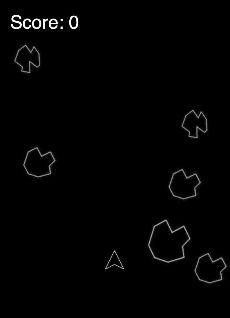
Choosing to take Intro to IM as my first coding experience was akin to taking a giant leap for me. Yet I am surprised how bit by bit this class cleared so many concepts and provided me with the hands-on experience I needed in coding platforms. For my final project, as promised and discussed in previous posts, I tried to create a painting/drawing platform by connecting P5js to Arduino. Interactive Media in itself is a form of creative expression and I wanted this project to be a platform for a digital form of artistic expression. This attempt at coding as etch-a-sketch is an ode to that childish playfulness that often gets subdued as we grow up.
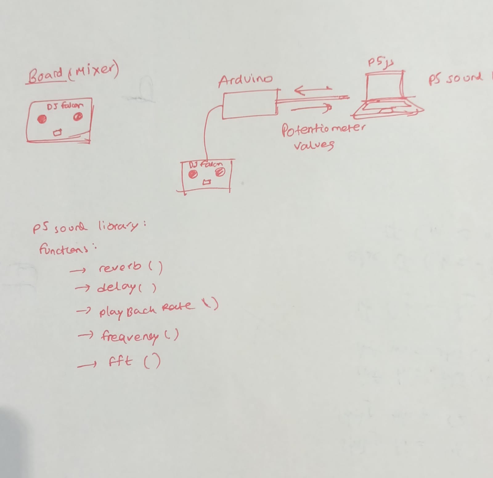
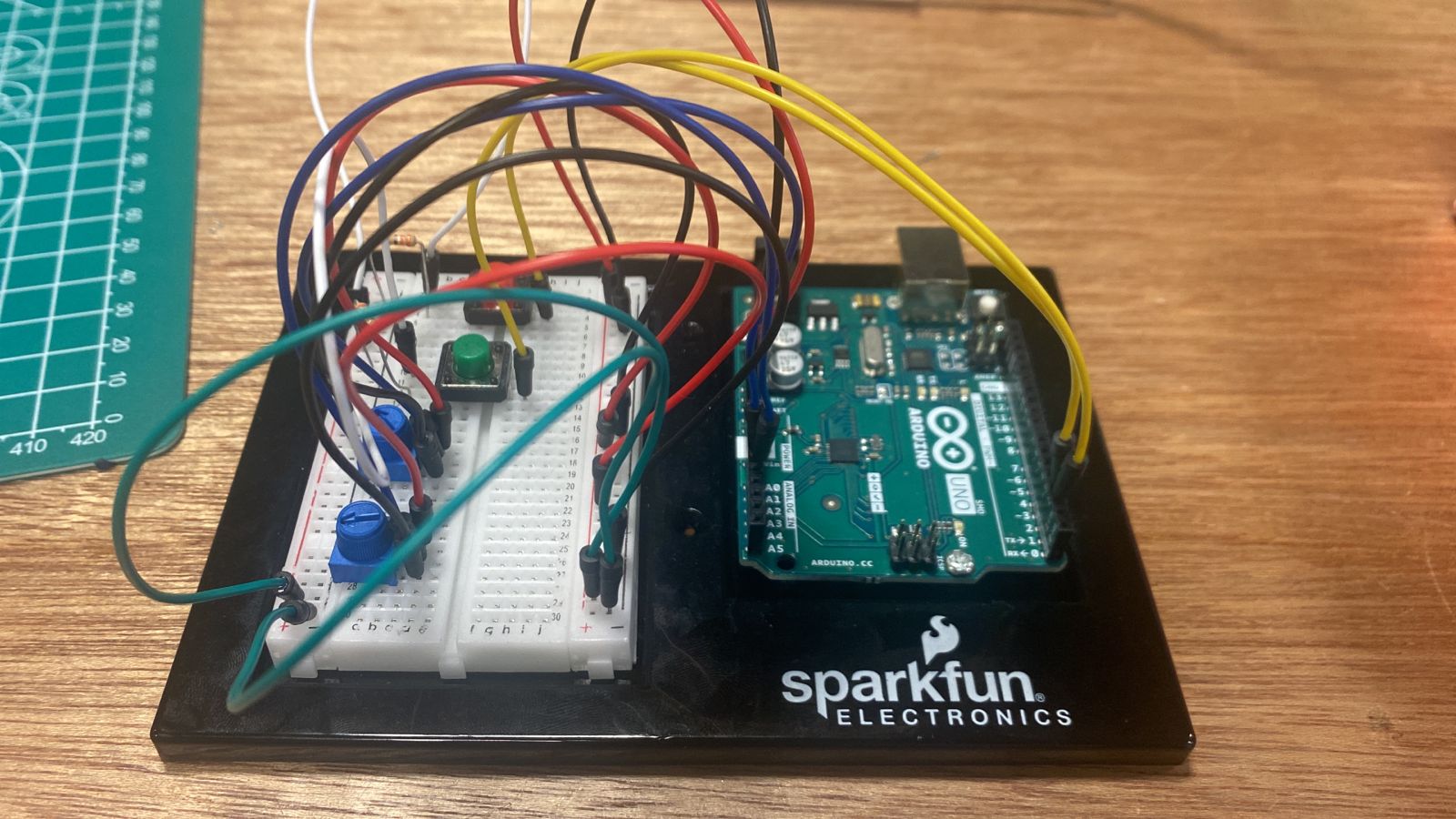
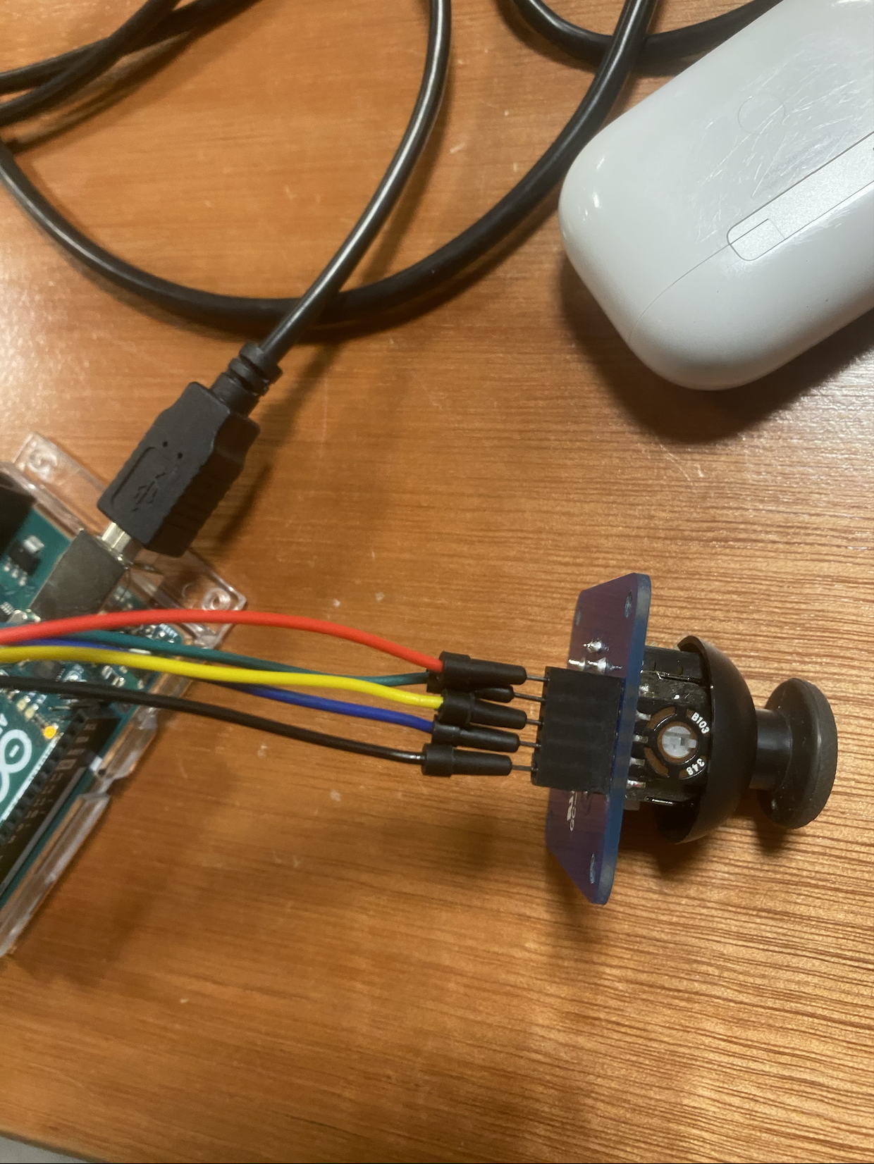
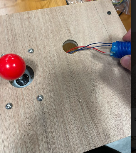
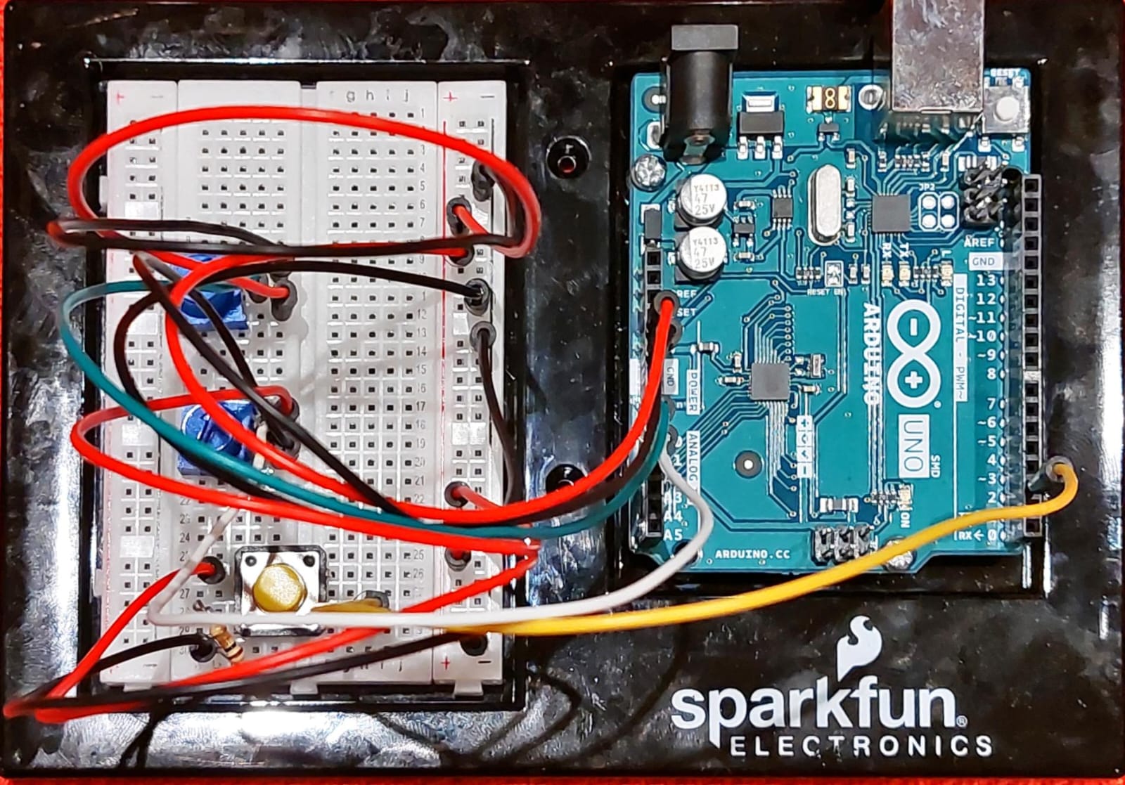
Arduino setup-

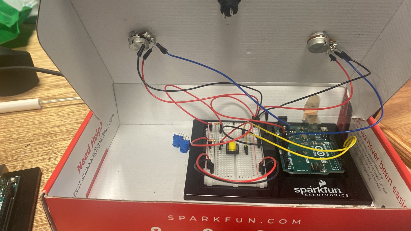
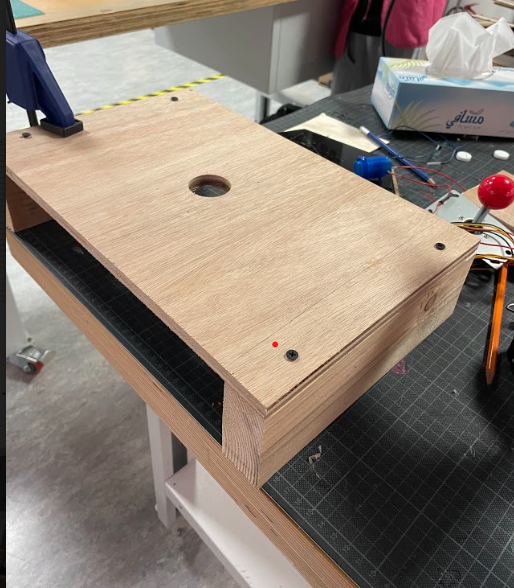
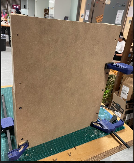
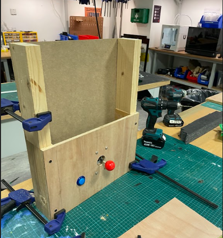
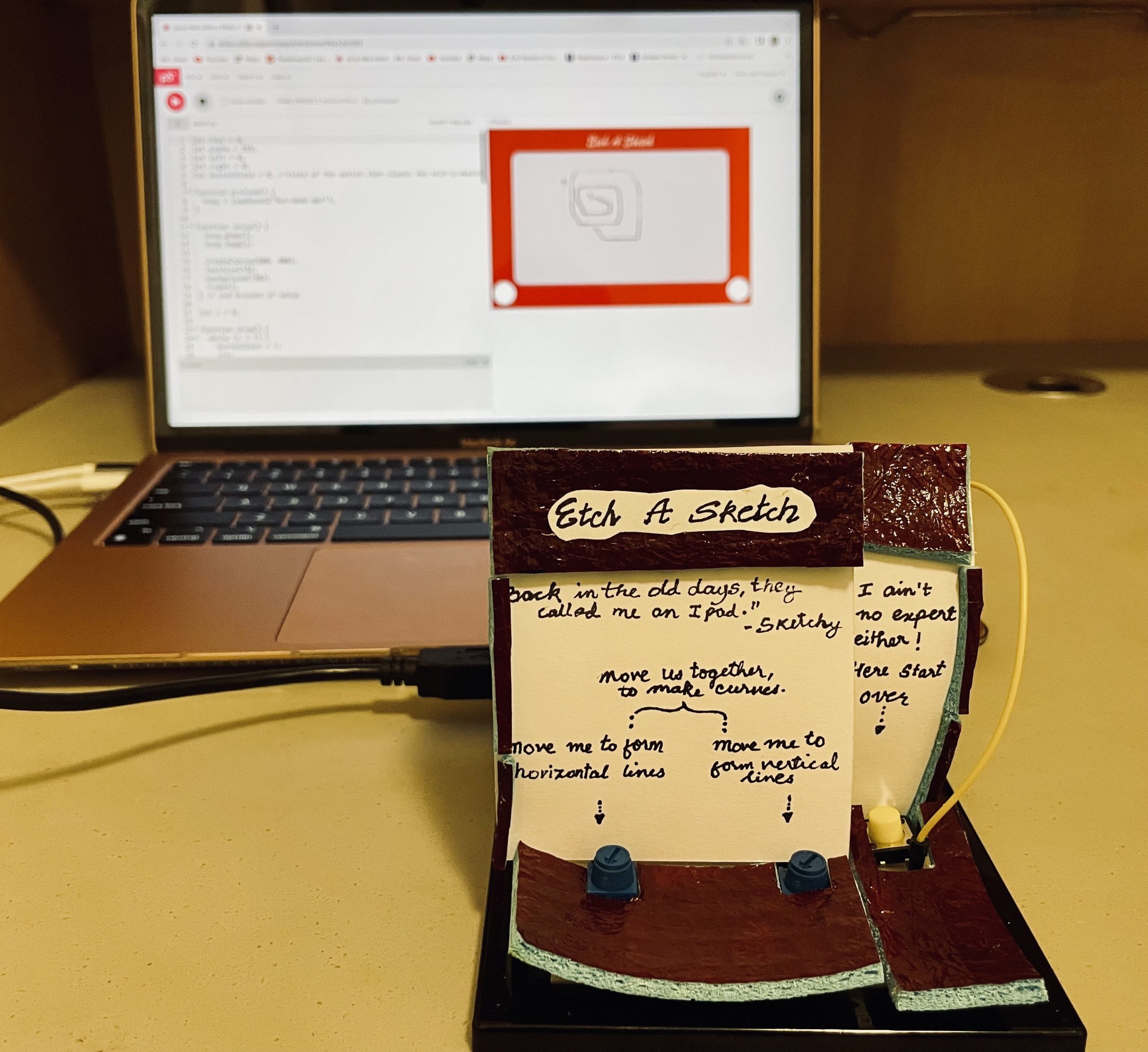
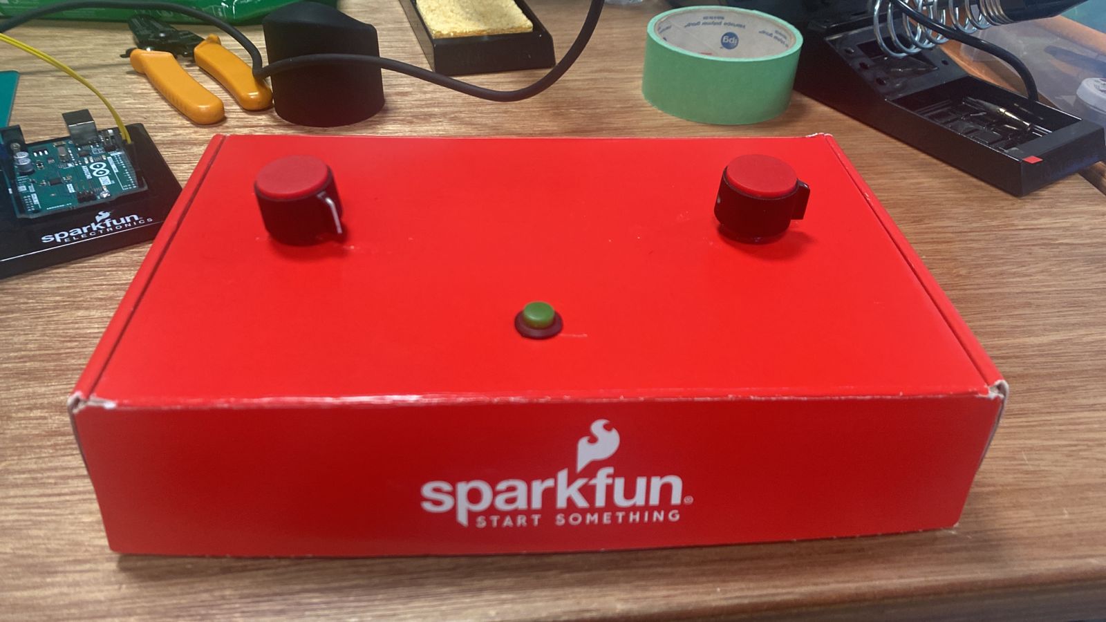
Revised console-setup-

Implementation

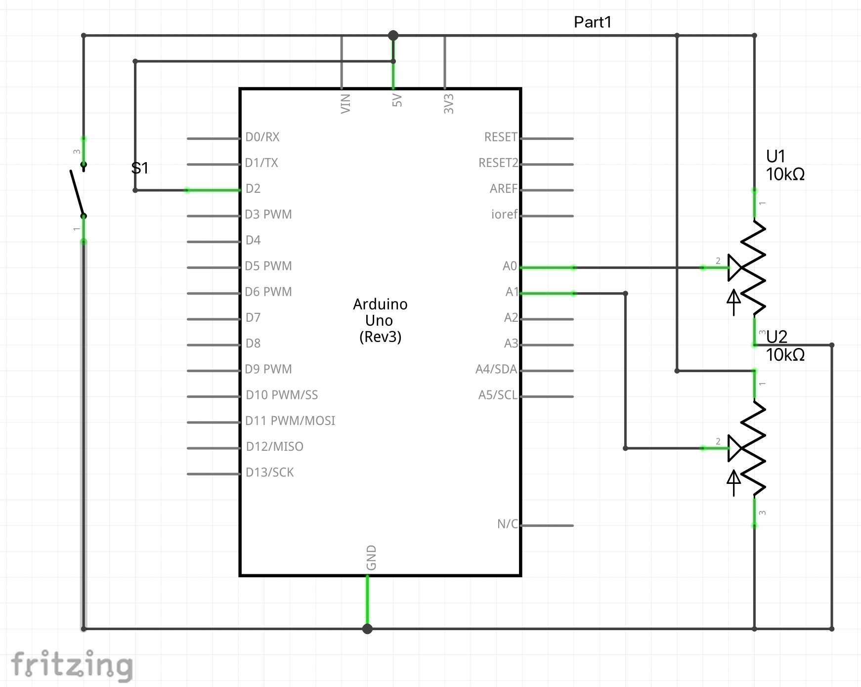
The project mainly includes two potentiometers and a switch. The values sent from the first potentiometer map the vertical movement of the ellipse that is drawn based on its R-value (RGB color). It moves the ellipse up and down. Similarly, the movement of the second potentiometer maps the horizontal value of the ellipse and makes it go left and right. The way in which the first potentiometer controls the r-value, the second potentiometer also adjusts the alpha value of the ellipse that is drawn. when both the potentiometers are moved together, the user is able to draw curved lines as well. The third main component is the switch which when pressed clears the canvas for a new sketch to be drawn.

The p5.js component is crucial to the functioning of the program since it handles everything from sending data to the Arduino to displaying the design that is drawn in the most effective way. Three functions are primarily added in the p5js code. They include draw, readSerial, and frame. The draw function is where the ellipse is drawn and moved along the canvas. The readSerial function establishes the serial connection between the Arduino port and the p5js sketch when the space bar is pressed by the user within the canvas based on bilateral handshaking. After pressing the space bar, the port selection dialog box pop-ups from which the suitable port is selected. A global variable called the “buttonState” is defined at the beginning of the code that clears the canvas every time the digital switch is pressed or in other words when its state changes from 0 to 1.

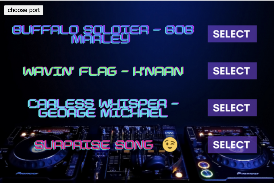
Finally, the frame function deals with the aesthetics of the project. It draws the authentic etch-a-sketch style background to make the screen look more inviting. I have also looped a whimsical song that plays in the background every time the serial connection is established and as long as the program is running.

The Arduino side mainly executes the commands that are sent by the p5js sketch. The analog sensors (potentiometers) are read and then their values are printed similarly through the addition of a local variable within the loop function, the digital values being sent from the switch are read. The pin mode has been added in the setup as the input. The other digital and analog values are added and read in the loop function.

Arduino Code

// Inputs:
// - A0 - first potentiomemter 
// - A1 - second potentiomemter
// - 2  - switch 


void setup() {
  // Serial communication is started to send the data
  Serial.begin(9600);

   pinMode(2, INPUT); 


  // bidirectional communication starts
  while (Serial.available() <= 0) {
    Serial.println("0,0"); // send a starting message
  }
}

void loop() {
  // waits to receive data from p5js first and then starts executing
  while (Serial.available()) {

    int left = Serial.parseInt();
    int right = Serial.parseInt();
    if (Serial.read() == '\n') {
      int sensor = analogRead(A0);
      delay(5);
      int sensor2 = analogRead(A1);
      delay(5);
      int button = digitalRead(2);
      delay (5);

      Serial.print(sensor);
      Serial.print(',');
      Serial.print(sensor2);
      Serial.print(',');
      Serial.println(button);
    }
  }
}

P5js sketch and Code

Components I am Proud of

Overall, I am quite pleased with my humble outcome as it performs its bilateral communication functions quite smoothly. I am particularly proud of how the addition of mapping the alpha values of the ellipses that are being drawn on the screen gives a special “sketchy” effect to the project. Moreover, as we toggle the speed of the potentiometers the density of the stroke changes which is quite similar to the manner in which strokes that are drawn by a sketch pen change with varying pressure.

A few Sketches and user interaction-

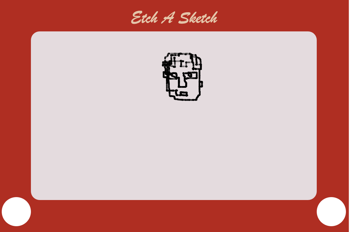
Blind Contouring a portrait-


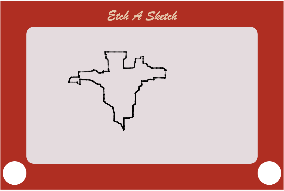
Plotting the map of India-

User interaction-


Future Improvements

I would have loved to add another switch in the project that allowed the user to change the color of the stroke from black to another color. But through my best possible attempts in the given time frame, I was able to add a switch that changes the color of the stroke when it is being continuously pressed. This beat its practical purpose though since the user would have to use both of his hands to toggle the potentiometers and at the same time keep pressing the switch.

Final Progress

I have my circuit ready with 2 buttons: one for start/restart & another for “collect”, and a potentiometer to inflate the balloon. I wanted to use a pressure sensor for blowing but the readings weren’t too sensitive to human blowing and it wasn’t too accurate. So, I decided to keep it simple and make it like an arcade game with hand interaction only. I edited my code to read the potentiometer values directly from Arduino.

while (Serial.available()) {
    int left = Serial.parseInt();
    int right = Serial.parseInt();
    if (Serial.read() == '\n') {
      digitalWrite(2, left);
      digitalWrite(5, right);
      int sensor = analogRead(A0); //potentiometer 
      delay(1);
      int sensor2 = digitalRead(7); //start button

The challenging part was having a steady serial connection from Arduino. I realized that it would go faster if there are equal number of data coming in and out of Arduino (even though I am not sending anything back to Arduino). I consider my project 80% done and hope to have more progress until the showcase.

Final Project DJ Falcon – Q M and Daniel

So, here it is! After fixing hundreds of errors and spending countless man hours, we finally have our project– DJ Falcon!

DJ Falcon:

Using Arduino and p5js, we created DJ Falcon, an audio mixer set that modifies tracks and makes everyone jam to the tunes. The mixer also has a visualizer whose waves sync with the audio being played.

The user is welcomed with this screen:

You can then choose a song from the list to mix:

Then you rotate the knobs on the mixer to shake things up!

The Process:

There are two parts to this code – the p5js part and the Arduino part.

Components Used:

Ph a000066 iso (1) ztbmubhmho Arduino UNO board

12002 04 Breadboard

09939 01 Rotary Potentiometers (2)

19c7994 40 Push down Switch (1)

Mfr 25frf52 10k sml Resistors

11026 02 Jumper Wires

Apps and Online Services:

Ide web  Arduino IDE Making p5.js Accessible. by Luis Morales-Navarro and Mathura… | by Processing Foundation | Processing Foundation | Medium p5js

The Process:

We started the project by drawing out everything first in a notebook. Here’s the very first (very rough) sketch of our idea:

I decided to work on the interface for the mixer and took care of the code and fixing the issues that came up, while QM was going to put together the circuit and the hardware. After setting up the basic circuit on the breadboard and building a very basic interface with buttons on p5js, we had to connect the both.

We then incorporated the p5js sound library in our p5 code. We used the built in reverb, delay, frequency functions and tested those out together by uploading an mp3 file on p5js. It was all working fine. We had to then figure out how to take values from the potentiometer, map them, and use them as arguments for the sound functions.

But before that, we had to write code for reading the values from the pin. QM got to writing the code for the Arduino IDE while Daniel got to figuring out how to take those inputs in p5js. This is where we hit our first roadblock. We just could not figure out the correct p5js library for serial communication and also couldn’t figure out how to separate the values we got from the potentiometer and store them in variables. With a little help from Professor Ang, we finally figured out the right library and used a list to store our values from where we used split() and trim() function to separate the values from each input. This is the bit of code that helped us do it:

function serialEvent() {
if (serial.available() > 0) {
serialData = serial.readLine();
if (serialData) {
// false if serialData == null
console.log(serialData);
serialData = trim(serialData); // remove trailing whitespace
serialValues = split(serialData, ","); // split the string to array
console.log("serialValues ", serialValues);
rev_value = Number(serialValues[0]);
console.log("Rev: " + rev_value);
rate_value = Number(serialValues[1]);
console.log("Rate: " + rate_value);
play_value = Number(serialValues[2]);
console.log("Play/pause: " + play_value);
standby_value = Number(serialValues[3]);
console.log("Standby: " + standby_value);
rev_mapped = map(rev_value, 0, 1023, 0, 100);
rate_mapped = map(rate_value, 0, 1023, 0, 200);
console.log("rev mapped: " + rev_mapped);
console.log("rate mapped: " + rate_mapped);
}
}
}

It’s also worth mentioning that some of the code for the serial connection were reusable code snippets written by Professor Sherwood and Ang from class examples.

This is how our board looked:

Once we connected the Arduino board and had the serial connection going, it was now time to map the values to fit into the arguments. I had a pretty solid grip on the ranges for the different music functions like the dryness and wetness of reverb, due to being a music major, and had a good understanding of how our random values would translate to what we hear (QM also ended up learning a fair bit about music at this point from Daniel).

But even then, it wasn’t smooth sailing. Although we had an understanding of the values, p5 was playing its sly tricks with us with the inner working (or should I say, inner loopings!) of the draw() function causing a haphazard in the music where multiple tracks were playing by overlapping each other and it sounded more like a cacophony than a vibey night at a club.

One evening, after working for more than 5 hours continuously trying to solve these, we decided to call it a night and come back the next day.

Maybe sleeping on the bugs helped, because the next day, after the both of us worked simultaneously on our own laptops trying to fix the bugs, QM had a slight hint of a breakthrough when one of the buttons successfully paused the music without looping. Still it wouldn’t make it play again.

But then…(drumrolls) a moment of genius from Daniel and some tweaking of the code and suddenly everything worked! Words fail to describe how victorious we felt at that moment:

Now it was time to put everything together. QM, with a noob-level experience in soldering decided to solder the board together and Daniel would give a finishing touch to the interface, incorporating a dope background, cool fonts and a cleaner look. Here’s some of that scrappy soldering work:

And here’s Daniel’s work on the interface:

We were both happy with the font and the look of the mixer and the DJ Falcon mixer was ready.

The Schematic:

Code: Arduino IDE

const int switchPin1 = 2;
const int switchPin2 = 3;
void setup() {
Serial.begin(9600);
pinMode(switchPin1, INPUT); // initialize serial communications
pinMode(switchPin2, INPUT);
}

void loop() {
// read the input pin:
int pot = analogRead(A0);
int mappedPot = map(pot, 0, 1023, 0, 255);
Serial.print(pot);
Serial.print(",");
int potRev = analogRead(A1);
int mappedtest = map(potRev, 0, 1023, 0, 255);
Serial.print(potRev);
Serial.print(",");
int button1 = digitalRead(switchPin1);
int button2 = digitalRead(switchPin2);
Serial.print(button1);
Serial.print(",");
Serial.println(button2);
delay(1);
delay(100);
}

Code for p5js:

Improvements:

We had more ambitious ideas in mind like using the delay() feature and a standby button but those were causing bugs due to the draw() function of p5js, but we’re sure these can be implemented in the future.

Final Project Documentation

Game idea:
The Asteroids game is a classic arcade game that has been enjoyed by many people over the years. In this version of the game, you control a spaceship and must navigate through a field of asteroids, shooting them to destroy them and avoid being hit. The game is challenging and exciting, and the addition of the Arduino joystick adds a new level of interactivity. Working with p5js and Arduino was both fun and challenging. Combining these two technologies allowed me to create a dynamic game that could be controlled with a joystick.

Box:
Making the box for the joystick was a fun and challenging project. The first step was to gather the materials that I would need, which included wood, screws, and a joystick. I was fortunate to have a professor who was able to cut the pieces of wood to the right size, which saved me a lot of time and effort. Once the pieces were cut, I began the process of assembling the box. This involved screwing the pieces together and attaching the joystick. The process of attaching the joystick was complicated and took a lot of time, but it was rewarding to see the final product coming together. After the box was assembled, I decided to give it a coat of spray paint to make it look more polished and finished. This added an extra layer of protection to the wood and gave the box a more professional look. In the end, I was very happy with the way the box turned out. It was sturdy and well-constructed, and the addition of the joystick made it a perfect fit for my Asteroids game.

Implementation (p5js and Arduino):
Arduino code:

void setup()  
{
  Serial.begin(9600);
  pinMode(2, INPUT);
  digitalWrite(2,HIGH); 
  pinMode(A0, INPUT);
}

void loop() 
{
  int potVal = analogRead(A0);
  int buttonVal = digitalRead(2);
  Serial.print(buttonVal);
  Serial.print(",");
  Serial.print( potVal);
  Serial.println();
}


red – 5V
green – A0 (x-axis values)
yellow – A1 (y-axis values not used)
blue – 2 (button values)
black – GRW

p5js code:
These are the function used to connect the Arduino values with the game. The rest of the code is the one from my midterm project.

function makePortButton() 
{  
  portButton = createButton("choose port");
  portButton.position(10, 10);
  portButton.mousePressed(choosePort);
}

function choosePort() 
{
  if (portButton) portButton.show();
  serial.requestPort();
}
 

function openPort() 
{
  serial.open().then(initiateSerial);
 
  function initiateSerial() 
  {
    console.log("port open");
  }
  
  if (portButton) portButton.hide();
}
 
function portError(err) {
  alert("Serial port error: " + err);
}

function serialEvent() {
  
  let data = serial.readStringUntil('\n');

  try
  {
    values = split(data, ',');      
  }
  catch(err)
  {
    //print("NAN");
  }
  
}

function portConnect() {
  console.log("port connected");
  serial.getPorts();
}

function portDisconnect() {
  serial.close();
  console.log("port disconnected");
}
 
function closePort() {
  serial.close();
}


function controls2(x,y){

  if(!isNaN(y) && y!=2 && y > 0)
  {
     gamestatus = "running";
  }
  if (!isNaN(y) && y!=2 && y > 0)
  {
    makebullet(shooter.x,shooter.y);    
  }
  
}


function controls(x,y){
  
  if(!isNaN(y) && y!=2 && y > 0)
  {
     gamestatus = "running";
  }
  
    
  if(!isNaN(y) && y!=2 && fired == 0)
  {
    if(y>0)
     {
       makebullet(shooter.x,shooter.y);
       fired = 1;
     }
  }
  
  if(!isNaN(y) && y!=2 && fired != 0 && y == 0)
  {
    fired = 0;
  }
  if(x<340 && x>250)
  {
    rate = -2;
  }
  else if(x<250)
  {
    rate = -5;
  }
  else if(x>340 && x<680)
  {
    rate =0;
  }
  else if(x>680 && x<850)
  {
    rate = 2;
  }
  else if(x>850 && x<950)
  {
    rate = 5;
  }
  else
  {
    
  }
}

User experience:

Reflections and improvements:
Figuring out how to use p5js and Arduino together was not easy, but it was a rewarding experience. I learned a lot about programming and electronics as I worked on the project, and I was able to create a unique and engaging game. I am proud of the work that I put into the game, and I hope that others will enjoy playing it as much as I enjoyed making it. Overall, I am pleased with the final product of my Asteroids game. It is a fun and exciting game that is sure to provide hours of entertainment. The addition of the Arduino joystick makes it even more engaging, and I am glad that I was able to incorporate this technology into the game. I hope that others will enjoy playing it as much as I enjoyed creating it.

Final Project: progress update

Concept
Since last time I was not completely clear on the idea, I continued brainstorming. As a result, I came up with an idea that combines everything I had planned: a mini game with a winter (Christmas/New Year) theme and related to drawing. I will create a mini-game based on a fairy tale I was told as a child. I was told that at night in winter, Ayaz ata(Santa) and his magical assistants painted on the windows in the morning to delight children. Of course, these “patterns” on the windows do not appear by themselves, but when the weather is very cold, the windows freeze and there is a miracle of nature. To recreate this idea, I will use the potentiometer as a basis for random and free drawing. Through the potentiometer, the user will be able to control the step-size and feel themselves as a character of my childhood fairytale.

Here are the photos I was inspired by:
Frost on the window photo
Also, using p5js I will create a nice background which will include snow outside and snowflakes falling on the ground. I will add a window to my image and try to make something similar to this illustration.
Winter cozy window

I want my idea to be an interactive mini game where the user can draw his pattern and then save it. Inspiration: https://vividfax.itch.io/ceramic-flux
This game is about ceramic flux, where the user can draw anything on flux, then fire and be done with that. I like idea of adding a little bit more of interactivity.
Progress:
So far I have all basic things settled, everything works individually and needs to be put together.
* I made a base for my background:

To do this, I used my knowledge from past assignments about generative art and also briefly skimmed through TheCodingTrain youtube channel resources.
* Video video test
Arduino code:

void setup() {
// put your setup code here, to run once:
Serial.begin(9600);
}
void loop() {
// put your main code here, to run repeatedly:
int potentiometer = analogRead(A0);
int mappedPot = map(potentiometer, 0, 1023, 0, 30);
Serial.write(mappedPot);
delay(1);
}

P5:
The variable inData is used to manage the intervals in this code.The serial.on(“data”, serialEvent) line of code means that when there is new data sent through the serial connection, the serialEvent() function will be called. Inside this function, we update the inData variable to read the signal from the Arduino board. As the input type is a string, it needs to be changed to a number with inData = Number(serial.read()).

Next?
-develop more, connect all parts
-add some interesting things with LEDs for creativity
-play with bg in p5js

Final Project Progress

During the past week, I spent most of the time working on the physical structure of my project because this was the most confusing part for me and I did not have any experience with using wood and drilling stuff on wood. After going through a long process of cutting wood, drilling holes into the wood, then adding screws between wooden pieces using different drill bits, I was finally able to almost complete my physical structure and house the different devices inside my wooden building. In this blog I will demonstrate the different stages I went through to achieve the desired output.

The professor at first helped me with cutting three wooden pieces, one large piece that is placed on top of the two other pieces. After that, the professor also helped me in drilling a big hole in the middle of the wood to attach the joystick to it. Then I had to use the drill for the first time to drill four different holes on the sides of the big wooden piece and on the two other wooden pieces. To find the place where I am supposed to drill the holes I used a pencil and a ruler, then I used drill bits with size of 5mm to screw the 5mm screws in my wooden structure, I was able to get the following output from this step.

Then after that I was able to attach the joystick to this physical structure by using the four of the following type of bolts. I also attached nuts to these bolts to keep them in place. I tested the joystick after that and made sure that it is tightly fit in place.

After that I also wanted to make the game more interactive and decided to add a blue butto to allow the user to control the game. To add this button I had to solder stranded wires onto the button. Then I had to solder these stranded wires to solid wires so that I can attach them to the breadboard.

To add the blue button to my physical structure I had to drill another hole on top of my physical structure. However, I did not know how to do this because it was difficult to control the big drilling tip seen below and I was not getting the desired result as you can see in the next photo.

Then I decided to extend on this physical structure by adding another wooden piece alongside the current one to place my laptop on it. At first I added a wooden piece on the bottom to support everything and to ensure that the bread board and the arduino are supported, as seen below

I was finally able to extend my physical structure and now I have a place to put my laptop finally on. Therefore, my physical structure can support my game and I tested out the functionality of the game below, but could not use the sound of the game because there was an ongoing class at the same time.

Here is a link to the video:Demonstration of my game

Final Project Concept

Ideas:
I brainstormed for a while on what I could create using both arduino and p5js. My first idea was to add some changes to my game that I created for the midterm project. I wanted to control the movement of the player in the game with sensors and add some extra features controlled with the help of the arduino kit. The second idea was to draw using a joystick. I was inspired by this video: https://www.youtube.com/watch?v=jnZWHbsNSUk
Since I really like the idea of drawing with the interaction of P5js and Arduino, I plan to do something connected with sketching. Also, I want my project to have a winter atmosphere and the concept to be related to the upcoming holidays. For instance : https://markerplay.itch.io/yolka
To make my project more entertaining , I plan to make something like a game.The final version should include:
* Start/Finish Page
* Interactive background(probably will use experience from work with generative artworks in p5js)
* Sound
* Control from arduino with joystick/potentiometer/sensor/switch

Final Project Documentation: DJ Falcon (Daniel and QM Naushad)

So, here it is! After fixing hundreds of errors and spending countless man hours, we finally have our project– DJ Falcon!

DJ Falcon:

Using Arduino and p5js, we created DJ Falcon, an audio mixer set that modifies tracks and makes everyone jam to the tunes. The mixer also has a visualizer whose waves sync with the audio being played.

The user is welcomed with this screen:

You can then choose a song from the list to mix:

Then you rotate the knobs on the mixer to shake things up!

The Process:

There are two parts to this code – the p5js part and the Arduino part.

Components Used:

Ph a000066 iso (1) ztbmubhmho      Arduino UNO board

12002 04      Breadboard

09939 01      Rotary Potentiometers (2)

19c7994 40      Push down Switch (1)

Mfr 25frf52 10k sml     Resistors

11026 02      Jumper Wires

Apps and Online Services:

Ide web       Arduino IDE

Making p5.js Accessible. by Luis Morales-Navarro and Mathura… | by Processing Foundation | Processing Foundation | Medium        p5js


The Process:

We started the project by drawing out everything first in a notebook. Here’s the very first (very rough) sketch of our idea:

Daniel decided to work on the interface for the mixer while QM was going to put together the circuit and the hardware. After setting up the basic circuit on the breadboard and building a very basic interface with buttons on p5js, we had to connect the both.

We then incorporated the p5js sound library in our p5 code. We used the built in reverb, delay, frequency functions and tested those out together by uploading an mp3 file on p5js. It was all working fine. We had to then figure out how to take values from the potentiometer, map them, and use them as arguments for the sound functions.

But before that, we had to write code for reading the values from the pin. QM got to writing the code for the Arduino IDE while Daniel got to figuring out how to take those inputs in p5js. This is where we hit our first roadblock. We just could not figure out the correct p5js library for serial communication and also couldn’t figure out how to separate the values we got from the potentiometer and store them in variables. With a little help from Professor Ang, we finally figured out the right library and used a list to store our values from where we used split() and trim() function to separate the values from each input. This is the bit of code that helped us do it:

function serialEvent() {
  if (serial.available() > 0) {
    serialData = serial.readLine();
    if (serialData) {
      // false if serialData == null
      console.log(serialData);

      serialData = trim(serialData); // remove trailing whitespace
      serialValues = split(serialData, ","); // split the string to array
      console.log("serialValues ", serialValues);

      rev_value = Number(serialValues[0]);
      console.log("Rev: " + rev_value);

      rate_value = Number(serialValues[1]);
      console.log("Rate: " + rate_value);

      play_value = Number(serialValues[2]);
      console.log("Play/pause: " + play_value);

      standby_value = Number(serialValues[3]);
      console.log("Standby: " + standby_value);

      rev_mapped = map(rev_value, 0, 1023, 0, 100);
      rate_mapped = map(rate_value, 0, 1023, 0, 200);

      console.log("rev mapped: " + rev_mapped);
      console.log("rate mapped: " + rate_mapped);
    }
  }
}

It’s also worth mentioning that some of the code for the serial connection were reusable code snippets written by Professor Sherwood and Ang from class examples.

This is how our board looked:

Once we connected the Arduino board and had the serial connection going, it was now time to map the values to fit into the arguments. Daniel, being a Music major, had a pretty solid grip on the ranges for the different music functions like the dryness and wetness of reverb and had a good understanding of how our random values would translate to what we hear (QM also ended up learning a fair bit about music at this point from Daniel).

But even then, it wasn’t smooth sailing. Although we had an understanding of the values, p5 was playing its sly tricks with us with the inner working (or should I say, inner loopings!) of the draw() function causing a haphazard in the music where multiple tracks were playing by overlapping each other and it sounded more like a cacophony than a vibey night at a club.

One evening, after working for more than 5 hours continuously trying to solve these, we decided to call it a night and come back the next day.

Maybe sleeping on the bugs helped, because the next day, after the both of us worked simultaneously on our own laptops trying to fix the bugs, QM had a slight hint of a breakthrough when one of the buttons successfully paused the music without looping. Still it wouldn’t make it play again.

But then…(drumrolls) a moment of genius from Daniel and some tweaking of the code and suddenly everything worked! Words fail to describe how victorious we felt at that moment:

Now it was time to put everything together. QM, with a noob-level experience in soldering decided to solder the board together and Daniel would give a finishing touch to the interface, incorporating a dope background, cool fonts and a cleaner look. Here’s some of that scrappy soldering work:

And here’s Daniel’s work on the interface:

We were both happy with the font and the look of the mixer and the DJ Falcon mixer was ready.

The Schematic:

Code: Arduino IDE

const int switchPin1 = 2;
const int switchPin2 = 3;

void setup() {
  Serial.begin(9600);
  pinMode(switchPin1, INPUT); // initialize serial communications
  pinMode(switchPin2, INPUT);
}
 
void loop() {
  // read the input pin:
  int pot = analogRead(A0); 
  int mappedPot = map(pot, 0, 1023, 0, 255);
  Serial.print(pot);
  Serial.print(",");

  int potRev = analogRead(A1);
  int mappedtest = map(potRev, 0, 1023, 0, 255); 
  Serial.print(potRev);
  Serial.print(",");

  int button1 = digitalRead(switchPin1);
  int button2 = digitalRead(switchPin2);
  Serial.print(button1);
  Serial.print(",");
  Serial.println(button2);

  delay(1);


  delay(100);                                            
}

Code for p5js:

Improvements:

We had more ambitious ideas in mind like using the delay() feature and a standby button but those were causing bugs due to the draw() function of p5js, but we’re sure these can be implemented in the future.


1962 – Aadil, Janindu, and Tarek

Project Overview:

The three of us collectively decided to make something similar to an arcade machine as it was a very exciting part of our childhoods. Therefore, the project is a collection of three games that are designed to be played using an Arduino controller. The games include Flappy Bird, a popular mobile game in which the player controls a bird and navigates through obstacles; Racing Game, in which the player controls a race car and avoids colliding with the randomly generated cars as the race car overtakes them; and Space Invaders, a classic arcade game in which the player controls a spaceship and fights against invading aliens.

Arduino to P5js communication:

int button = 2;
int pot = A0;
int lastPotValue;
int lastbutton;
 
long previousmill = 0;
long timebutton = 500;
 
void setup() {
  // put your setup code here, to run once:
  Serial.begin(9600);
  pinMode(button, INPUT_PULLUP);
  pinMode(pot, INPUT);
}
 
int getpot(){
  int potValue = analogRead(pot)/255  ;
  int temp;
  if(potValue == 2 || potValue == 1){
    temp = 1;
  }else if(potValue == 3 || potValue == 4){
    temp = 2;
  }else{
    temp = 0;
  }
  return temp;
}
 
void loop() {
  int potValue = getpot();
  int buttonState = !digitalRead(button);
  long currentmill = millis();
 
  Serial.println(String(buttonState) + "," + String(potValue));
  
  if(buttonState == 1 && currentmill - previousmill >= timebutton){
    previousmill = currentmill;
   
 
    lastbutton = buttonState;
  }
}

We implemented this using the web serial. Here is how it briefly works: 

  1.       The user connects an Arduino board to their computer using a USB cable. 
  2.       The user writes and uploads a sketch (see above for the code) to the Arduino board that defines the behavior of the board and the data that it will send to the computer. 
  3.     The user opens a P5.js sketch in their web browser and includes the p5.webserial.js library in their code. 
  4.       The user adds event listeners to their P5.js sketch that will be called when the user connects or disconnects from the Arduino board, when the Arduino board is ready to be connected to, when there is an error communicating with the Arduino board, or when data is received from the Arduino board. 
  5.       The user calls the getPorts() method of the p5.WebSerial object to check for any available Arduino boards. If an Arduino board is available, the portavailable event listener is called, which can be used to open a connection to the Arduino board. 
  6.       Once the connection to the Arduino board is established, the user can send data to the Arduino board using the send() method of the p5.WebSerial object. The user can also receive data from the Arduino board using the data event listener, which is called whenever data is received from the Arduino board. 
  7.       The user can use the received data from the Arduino board to control the behavior and appearance of their P5.js sketch. The user can also send data from the P5.js sketch to the Arduino board to control the behavior of the Arduino board. 
  8.       When the user is finished using the Arduino board, they can close the connection to the board using the close() method of the p5.WebSerial object.

Flappy Bird:

Code:

function restart(){
  menu = 0;
  bird = new Bird(WIDTH / 2, HEIGHT / 2, 30);
  pipes = new Pipes(60, 200, 130);
  SCORE = 0;
  SCROLL_SPEED = 4;
  lives = 5;
}

function getRndInteger(min, max) {
  // https://www.w3schools.com/js/js_random.asp
  return Math.floor(Math.random() * (max - min)) + min;
}


function StartGame(){
  background(bg);
  fill("#7cfc00");
  rect(0, HEIGHT - GROUND_HEIGHT, WIDTH, HEIGHT);

  bird.draw();
  bird.update();
  bird.checkDeath(pipes);
  
  pipes.update();
  pipes.drawPipes();

  fill(255);
  textSize(60);
  textAlign(CENTER);
  text(SCORE, WIDTH / 9, HEIGHT / 7);
  textSize(30);
  text("lives: "+lives,WIDTH - WIDTH / 4, HEIGHT / 9);
  textAlign(CORNER);
}


class Bird {
  constructor(x, y, size) {
    this.x = x;
    this.y = y;
    this.size = size;
    this.vely = 0;
  }

  draw() {
    //fill("#eaff00");
    //circle(this.x+112.5, this.y-112.5, this.size);
    image(b,this.x-this.size, this.y-this.size,this.size, this.size);
    //image("cow.jpg",this.x, this,y);
  }

  update() {
    this.y += this.vely;
    this.vely = lerp(this.vely, GRAVITY, 0.05);
    this.y = Math.max(this.size / 2, Math.min(this.y, HEIGHT - GROUND_HEIGHT - this.size / 2));
  }

  flap() {
    this.vely = -JUMP_HEIGHT;
    jump.play();
  }

  checkDeath(pipes) {
    for (var pipe of pipes.pipes_list) {
      if (this.x + this.size / 2 > pipe.x && pipe.height && this.x - this.size / 2 < pipe.x + pipes.width) {
        if (this.y - this.size / 2 <= pipe.height || this.y + this.size / 2 >= pipe.height + pipes.gap) {          
          // window.location.reload();
          lives--;
          oof.play();
          if(lives === 0){
              // losing1.play();
              // restart(); 
              // break;
            window.location.reload();
          }
          pipes.pipes_list.splice(pipes.pipes_list.indexOf(pipe),1);
          pipes.retq();
          
        }
      }
      if (this.x - this.size / 2 > pipe.x + pipes.width && pipe.scored == false) {
        SCORE += 1;
        pipe.scored = true;
      }
    }
  }
}


class Pipes {
  constructor(width, frequency, gap) {
    this.width = width;
    this.frequency = frequency;
    this.gap = gap;

    this.pipes_list = [
      { x: 500, height: getRndInteger(this.gap, HEIGHT - GROUND_HEIGHT - this.gap), scored: false },
      { x: 500 + this.width + this.frequency, height: getRndInteger(this.gap, HEIGHT - GROUND_HEIGHT - this.gap), scored: false }
    ];
  }

  update() {   
    for (var pipe of this.pipes_list) {
      pipe.x -= SCROLL_SPEED;
      if (pipe.x + this.width <= 0) {
        pipe.x = WIDTH;
        pipe.height = getRndInteger(this.gap, HEIGHT - GROUND_HEIGHT - this.gap - this.gap);
        pipe.scored = false;
      }
    }
  }
  
  retq(){
    this.pipes_list = [
      { x: 500, height: getRndInteger(this.gap, HEIGHT - GROUND_HEIGHT - this.gap), scored: false },
      { x: 500 + this.width + this.frequency, height: getRndInteger(this.gap, HEIGHT - GROUND_HEIGHT - this.gap), scored: false }
    ];
  
  }

  drawPipes() {
    fill((0),(150),(0));
    for (var pipe of this.pipes_list) {
      rect(pipe.x, 0, this.width, pipe.height);
      rect(pipe.x, HEIGHT - GROUND_HEIGHT, this.width, -HEIGHT + pipe.height + GROUND_HEIGHT + this.gap);
    }
  }

}

The getRndInteger() function is a helper function that returns a random integer between two given values. This function is used to randomly generate the heights of the pipes in the game. The Bird and Pipes classes define the objects that appear in the game. The Bird class has a draw() method that is used to draw the bird on the screen, an update() method that is used to update the bird’s position and velocity, a flap() method that causes the bird to jump upwards, and a checkDeath() method that checks if the bird has collided with any of the pipes and ends the game if necessary. The Pipes class has an update() method that updates the positions of the pipes and a drawPipes() method that draws the pipes on the screen. Overall, the code defines a simple game in which the player controls a bird and must avoid colliding with pipes by jumping over them. The game keeps track of the player’s score and ends if the bird hits a pipe. 

Racing Game:

The generateCars() function is used to randomly generate cars that appear on the screen and the displayCars() function is used to draw the cars on the screen. The displayScore() function is used to display the player’s current score on the screen. The potentiometer returns three readings: 0,1, and 2 based on the positioning. Based on the number being returned by the potentiometer – we handle the car movement. 

Space Invaders:

function startPage(){
  textSize(27);
  fill(250);
  text("Space invador",27,250);
  textSize(15);
  text("press enter to start",52,290);
}

function removeRocks(){
  rocks.splice(0,rocks.length);
  rocksctr = 0;
}


function displaybullets(){
    for(let i = 0; i < bullets.length; i++){
      bullets[i].display();
      
      if(bullets[i].y < 0){
        bullets.splice(i,1);
        numBullets--;
      }
      
    }
  // console.log(numBullets);
}

function generaterocks(){
  let rand = int(random(0, 100));
  let rand2 = int(random(0, 100));
  if(rand % 7 == 0){
    if(rand2 % 3 == 0){
      if(rand2 % 2 == 0 && rand % 2 == 0){
          rocks[rocksctr] = new boulders();
          rocks[rocksctr].display();
          // console.log(rocksctr);
          rocksctr++;
        }
     }
  }
}

function displayrocks(){
  for(let i = 0; i < rocks.length; i++){
    rocks[i].display();
    // console.log(">",rocks.length);
    
    let temp = false;
    for(let j = 0; j < bullets.length; j++){
      if(bullets[j].didcollide(rocks[i])){
        temp = true;
        bullets.splice(i,1);
        numBullets--;
      }
    }
    
    if(mainship.didcollide(rocks[i])){
      rocks.splice(i,1);
      rocksctr--;
      gamestatus = "end";
      bomb.play();
      losing1.play();
      
    }else if(rocks[i].y > height || temp){
      rocks.splice(i,1);
      rocksctr--;
    }
  }
}
 var timechecker = 0.5;

function makebullet(x,y){
  bullets[numBullets] = new bulletClass(x,y);
  bullets[numBullets].display();
  numBullets++;
} 

Game Controls

Flappy Bird: Use the button on the arduino or the UP key to jump.

Racing Game: Use the potentiometer or left and right keys to control the car’s steering.

Space Invaders: Use the potentiometers or left and right keys to control the spaceship’s movement and button or UP key to fire lasers.


Conclusion 

This project demonstrates how to create and play games using p5.js and Arduino. The project includes three games that can be controlled using potentiometers and push buttons, and can be easily extended to include additional games and custom controller designs. We’re particularly proud of the aesthetics of the games – we were able to recreate what we initally had in mind. Furthermore, we had a lot of bugs which wouldn’t let the games run smoothly. We figured out how to implement the games smoothly by making changes in our algorithms and by handling specific types of errors which were mostly given by the arduino board. However, there is no proper restart function for flappy bird – if you lose, the canvas simply starts from scratch.

My contribution to the project was coding the flappy bird game, handling errors, debugging, and the documentation.  

Week 14 – Final Project Documentation

ORIGINAL CONCEPT

Our original idea was to create a set of friendship touch-lamps, where two lamps would be able to “communicate” with each other with the tap of a finger. Using p5 as our “remote controller”, each party would be able to choose the settings of the light they would like to send, ie. the color and the light patten. We wanted to include wireless communication in our project to stick with the vision that any two users, regardless of time, location, and proximity, would be able to communicate with that special someone through something that was visually compelling, and that the simple act of  sending lights to one another might foster some other type of communication.

IMPLEMENTATION

We believe that we stuck relatively closely to our original proposal, except that due to time and challenges with serial communication, we were not able to achieve this dual communication between two Arduino devices. Hence, although we were not able to achieve interaction from user to user, we were able to achieve interaction between user, lamp, and computer.

The conversation begins with the user interacting with p5. As mentioned above, our p5.js sketch acts as the “controller” of the lamp, providing animations and small game elements that make the programming more interesting. For example, in the second scene of the sketch, the user sees a heart flashing different colors in the center of the screen and is instructed to press the keyboard when the heart flickers to a color of their liking:

Additionally, in the following screen, the sketch displays 3 different light modes to choose from: flicker, wave, and pulse. above those 3 buttons is a corresponding icon that animates that is made to mimic the specific light mode:

Throughout the p5 program, data about the user’s choices are held in three important variables: picker.color, lightMode, and inData. picker.color is an instance variable of the colorPicker class, which was coded to build the flashing heart described above. It is initially set to a null value and is set once the user presses any key to choose their color. Similarly, lightMode is a variable made to hold an integer of 0, 1, or 2 which correspond to flicker, wave, and pulse respectfully. Initially set to a null value, it becomes set when the user presses the flicker, wave, or pulse button in the screen described above. We chose to have lightMode hold an integer, though it is more confusing the the reader, makes it easier to send it as serial data. The inData variable contains the data sent from Arduino through the serial.read() function, and sends a 0 or 1, depending on whether the touch sensor on the lamp has been touched or not touched. This code from Arduino is shown below:

touched = digitalRead(TOUCH_SENSOR); 
  if ((touched == 1) && (sensorState == LOW)) { 
    sensorState = HIGH;
    Serial.write(sensorState); 
  } 

  if ((touched == 0) && (sensorState == HIGH)) { 
    sensorState = LOW;
}

Finally, the conversation shifts between user-computer to user-lamp in the last screen of the p5 program (shown below), where it asks the user to touch the lamp in order to let p5.js know that it is “ready” to send the data to Arduino — “ready” meaning that inData is 1, the lightMode has been set, and picker.color has been set. The code that sends the serial data is also shown below:

if (inData == 1) { 
  // console.log('the color you chose:', colorValue); 
  // console.log('the light mode you chose:', lightMode);
  console.log(inData); 
  let r = red(picker.color); 
  let g = green(picker.color); 
  let b = blue(picker.color);
  
  
  let sendToArduino = r + "," + g + "," + b + "," + lightMode + "\n";
  serial.write(sendToArduino);

Once the data is sent, the “control” of the entire system is handed over to our Arduino code, which is the code that actually displays the lights, completing the final part of the user-lamp conversation. First, after reading the data from p5, it parses the data and organizes it into variables that hold the red, green, and blue color values, as well as the light mode, similar to how it is organized in p5:

while(Serial.available()){
  sensorState = LOW; 
  R = Serial.parseInt();
  G = Serial.parseInt();
  B = Serial.parseInt();
  //lightMode = Serial.read();
  lightMode = Serial.parseInt();

  if(Serial.read() == '\n'){
    Serial.write(0);
  }
}

Then, it uses those variables to create the different light modes (described in more detail in the previous posts):

  if (lightMode == 2){
  // WAVY
  //turn pixels to green one by one with delay between each pixel
  for (int pixel = 0; pixel < NUM_PIXELS; pixel++) { // for each pixel
    NeoPixel.setPixelColor(pixel, NeoPixel.Color(R, G, B)); // it only takes effect if pixels.show() is called
  
    NeoPixel.show();   // send the updated pixel colors to the NeoPixel hardware.
    NeoPixel.clear();
    
    delay(100); // pause between each pixel
  }

  // turn off all pixels for two seconds
  NeoPixel.clear();
  NeoPixel.show(); // send the updated pixel colors to the NeoPixel hardware.
  delay(10);     // off time
}

if (lightMode == 1) { 
// FLICKERING:
  //turn on all pixels to red at the same time for two seconds
  for (int pixel = 0; pixel < NUM_PIXELS; pixel++) { // for each pixel
    NeoPixel.setPixelColor(pixel, NeoPixel.Color(R, G, B)); // it only takes effect if pixels.show() is called
  }
  NeoPixel.show(); // send the updated pixel colors to the NeoPixel hardware.th
  delay(1000);     // on time

  // turn off all pixels for two secondse
  NeoPixel.clear();
  NeoPixel.show(); // send the updated pixel colors to the NeoPixel hardware.
  delay(500);     // off time
}

if (lightMode == 3){
  //PULSING   
  uint16_t j;

  for (j = 0; j < 255; j++) {
    for (int pixel= 0; pixel < NUM_PIXELS; pixel++) {
      NeoPixel.setPixelColor(pixel, R, G, B);
      NeoPixel.setBrightness(j); 
    }
    NeoPixel.show();
    delay(20);
  }

  for (j = 255; j > 0; j--) {
    for (int pixel = 0; pixel < NUM_PIXELS; pixel++) {
      NeoPixel.setPixelColor(pixel, R, G, B);
      NeoPixel.setBrightness(j); 
      }
    NeoPixel.show();
    delay(20);
    Serial.println(j);
    }
  delay(100);
  //make sure to set all pixels back to full brightness for the other modes 
   for (int pixel = 0; pixel < NUM_PIXELS; pixel++) { 
    NeoPixel.setBrightness(255); 
  }
}

Note that once the lights are displayed, the data being written out to p5 is that the lamp is not-touched and is ready for the next round of data to be collected from p5. The user has the option to stop there, or can repeat the “cycle” as many times they wish by clicking the “send another” button in p5.

WHAT WE’RE PROUD OF

Something we like about our system that we think enhances the experience is the attention to detail and aesthetic of the p5 sketch. We chose the name “Distance makes the Heart and Glow Fonder” because it is not only a cute play on words, but also keeps with our neon theme. We also wanted all of our text and images to have flickering effect and a glowing effect (reference:  https://www.youtube.com/watch?v=iIWH3IUYHzM) to mimic real life neon signs and lights. Also, we felt that adding animations to the screen that shows the light modes not only made it more visually compelling but more intuitive for the user, given that the instructions of the program are minimal.

Though none of us have much experience with building, we wanted to push ourselves beyond the Arduino board we were given and try our best to make a lamp that didn’t look so obviously “Arduino”. Overall we are very happy with how it turned out, considering the time and resources we had. Everything we used to build it was made out of scrap materials found in the lab, and each part of the lamp is detachable by velcro, making it extremely easy to access the wiring and adjust things if needed.

FUTURE IMPROVEMENTS

In terms of the physical lamp, it would be nice to completely cover the wiring at the bottom with more acrylic panels. Perhaps remaking it using a different glue will also help get rid of the fogging happening on the current model.

In terms of our code, we would like to carry out our initial vision and create two lamps that can communicate with each other, and perhaps even have them communicate wirelessly.

DEMO

Below are some demo videos of our project:

Contribution to the project:

– I spent time working on the serial communication used to transmit messages from p5js to the Arduino.

– I spent time working on the Arduino code in implementing the various modes of light of the lamp.

– Worked together in constructing the lamp

– Worked together to document and compile the blog posts

– Worked together on bugs and last minute challenges