Serial Communication – Nouf and Zhaniya

Task 1

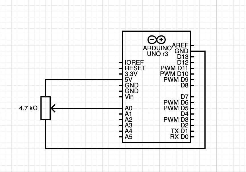
For the first task, we used potentiometer on our circuit and controlled the X_pos of an ellipse in p5js. We also set up a port choosing thing, so the code requested port connection every time we start the program.
Link to our full code:
https://editor.p5js.org/Zhaniya/full/ft2iMvilF
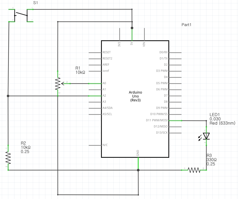
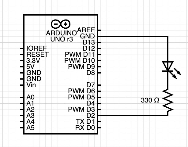
 

Circuit:

result:

Task 2

We used aaron sherwood’s code code which sends and receive data to the arduino. We tried to move those two lines of code

let sendToArduino = LED_value + "\n";
writeSerial(sendToArduino);

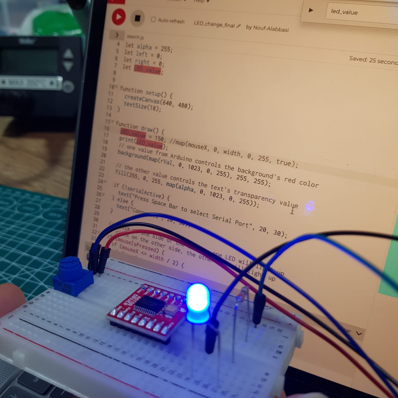
In the draw function instead of the readSerial() function, but that resulted in a errors with the writeSerial function. We also tried to remove the code in the readSerial function that waits for input from the arduino before sending anything while keeping the two lines of code where it originally is, but that wasn’t working either. We ended up using the original code, but we sent random values to p5js from the arduino and sending the LED brightness value (which is based on where the mouse is horizontally) to the arduino.

LED_value = map(mouseX, 0, width, 0, 255, true);
print(LED_value);

Here is a link to the code: https://editor.p5js.org/Nouf-Alabbasi/sketches/gJtQGnh0w

circuit:

the video below shows the LED reacting to the mouse movement (the first video shows the LED and the second Shows the mouse moving)


Task 3

For the third exercise we followed similar to exercise 2 steps to complete it. We used with gravity wind example with bouncing ball (https://editor.p5js.org/aaronsherwood/sketches/I7iQrNCull) to send the data to the Arduino. After that, we initialized LED_value and set up serial connection.

Code:
https://editor.p5js.org/Nouf-Alabbasi/sketches/Eq7USk-wJ


circuit:

Problems that we faced:

Some of the problems we faced were simply fixed by uploading the code to the arduino microcontroller but others were a little more challenging to fix. One thing that was not going the way we expected was the LED not gradually changing from one value to another. It seemed to jump from on to off which is not what we were going for.
Here is the p5js code:

// define the LED brightness as the mouse movement
LED_value = map(mouseX, 0, width, 0, 255, true);
print(LED_value);
…
let sendToArduino = LED_value + "\n";
writeSerial(sendToArduino);

And here is the Arduino code:

…
int LED_val = Serial.parseInt();
if (Serial.read() == '\n') {
analogWrite(2, LED_val);
…

One hypothesis is perhaps parseInt doesn’t handle decimals in numbers, so we expect that it might’ve stopped at the first part of the decimal before the decimal. The numbers should still be usable though, so this doesn’t fully explain why the LED wasn’t being controlled in the way we wanted. (After searching online we found that using parseFloat would be a better fit for our code.

Aisha – Ball Run Game Final Project Concept

For my final project, I want to create a 3d type of game where the ball has to jump on obstacles. The further you get the higher your score will be similar to subway surfer. To make it physically interactive, I want to have the Arduino connected to a glove so the user can move/tilt their hands to guide the ball onto the obstacle. If this doesn’t work I will use buttons to move left/right and jump. Once the ball falls a game-over screen will be displayed with the user’s score, high score, and option to restart the game.

Assignment 8: Serial Communication

Group: Aisha, Hessa, Joonha

Schematics includes all three exercises:

Exercise 1:

Arduino Code (Credit to Hessa):

void setup() {
  Serial.begin(9600); // initialize serial communications
}
 
void loop() {
  // read the input pin:
  int potentiometer = analogRead(A0);                  
  // remap the pot value to fit in 1 byte:
  int mappedPot = map(potentiometer, 0, 1023, 0, 255);
  // print it out the serial port:
  Serial.write(mappedPot);
  //Serial.println(mappedPot);
  // slight delay to stabilize the ADC:
  delay(1);                                            
}

p5js:


Exercise 2:

Arduino Code (Credit to Aisha):

int LED = 5;
void setup() {
  Serial.begin(9600);
  pinMode(LED, OUTPUT);
  // start the handshake
  while (Serial.available() <= 0) {
    Serial.println("Wait");  // send a starting message
    delay(300);               // wait 1/3 second
  }
}
void loop() {
  // wait for data from p5 before doing something
  while (Serial.available()) {
    int brightness = Serial.parseInt(); 
    if (Serial.read() == '\n') {
      analogWrite(LED, brightness); // turn on LED and adjusts brightness
      Serial.println("LIT"); 
    }
  }
}

p5js:

Working Video:


Exercise 3:

Arduino Included in the p5sketch (Credit to Joonha)


Working Video:

Abigail and Ahmed’s Final Project IDea

Interactive Artwork: Fern Plant Robot Instrument Thing


So for our project, we wanted to do something artistic. The idea we have, came from the following piece of computer graphic art:

Interactive Walls

The artwork is graphic and based around Max but we thought it would look really great if implemented in real life with servo motors and multicolored panels.

The panels will be mounted to servo motors and be multicolored to look aesthetically pleasing. The panels can be made out of acrylic material or something lighter like thin plywood or cardboard. Due to restrictions of the Arduino Uno, we will only be able to use a maximum of 12 panels for our interactive artwork.


Functionality:

We want the panels to depict a living, breathing, organism that reacts to different inputs; touch, noise, and input controls on a mounted panel. The artwork itself will have two speakers that will create a surround sound effect and can also output predetermined responses to different stimuli.

The control panel for the artwork will have a few buttons that will change modes. Modes can be an ambient mode that makes predetermined patterns, music mode which will make the artwork react to music playing, and a touch mode that will allow the audience to touch the artwork and have it react to their inputs.

The whole piece can be controlled by a single Arduino which will be responsible for the servo motors. For the buttons and knobs, we don’t think there will be enough I/O options on the Arduino Uno to make everything work so we will use a touchscreen with a p5js program to make digital buttons.

Concept Image:


Additional Information:

  1. The speaker chamber behind the art piece
  2. The initial look of the moving panels

We also found the following code that may help us during the production of this project:

Audio Reactive Program


Final Project (Preliminary Concept)

For my final project, I decided to upgrade the balloon game I developed for the midterm project. For the game itself, I want to have different colors that pop at different rates so this could be used as an analysis test for risk-taking abilities. To make it physically interactive, I will be adding sensors that detect blowing from the user in real life. One way I would do this is by making something spin as the user is blowing and then a motion sensor to detect the spinning (something like a fan). I can imagine this to be challenging, so plan B would be using a potentiometer or a button to inflate the balloon.

After inflating it, the user could “collect” the balloon of that round by pressing a button or a brake pedal and another round is displayed until the game ends. The piezo buzzer will be used for the popping sound of the balloon. The score will be displayed in a screen (LCD or neopixel).

I will also be developing the result to make it more specific than just a score; it would calculate the number of pumps based on the color and give specific personalized result on their learning abilities.

Serial Communication

Schematic: It includes all 3 exercises using 1 Arduino.

Exercise 1

Arduino Code:

void setup() {
  Serial.begin(9600); // initialize serial communications
}
 
void loop() {
  // read the input pin:
  int potentiometer = analogRead(A0);                  
  // remap the pot value to fit in 1 byte:
  int mappedPot = map(potentiometer, 0, 1023, 0, 255);
  // print it out the serial port:
  Serial.write(mappedPot);
  //Serial.println(mappedPot);
  // slight delay to stabilize the ADC:
  delay(1);                                            
}

Exercise 2 (cred to Aisha)

Arduino Code:

int LED = 11;

void setup() {
  Serial.begin(9600);
  pinMode(LED, OUTPUT);
  // start the handshake
  while (Serial.available() <= 0) {
    Serial.println("Wait");  // send a starting message
    delay(300);               // wait 1/3 second
  }
}

void loop() {
  // wait for data from p5 before doing something
  while (Serial.available()) {
    int brightness = Serial.parseInt(); 
    if (Serial.read() == '\n') {
      analogWrite(LED, brightness); // turn on LED and adjusts brightness
      Serial.println("LIT"); 
    }
  }
}

Exercise 3 (cred to Joonha)

Arduino Code included in the p5.js sketch.

Working Video:

Final Project- Preliminary concept

Concept

For the final project, I would like to improve on the pac-man game that I developed on p5.js for my midterm project. I was a bit confused about whether to start a new project from scratch or build up on my midterm project. However, I realized that my goal for this final project is to focus more on hardware and physical computing stuff. This is because I am not experienced in this area at all and would like to have the final project as an opportunity to challenge myself and try out designing creative things with Arduino.

While doing my midterm project I faced some minor issues with the code for the game. Therefore, before creating an interaction between p5.js and arduino, I would like to fix these issues in the game by using for example the colors of the pixels to determine when the pacman hits one of the walls instead of using many if statements.

Using hardware devices to Control the Game

After fixing these issues I would like to use different devices that we learned about in the class to control the game and make it more interactive with the user. For example, I can use four buttons to control the motion of pacman. One button that moves pacman up, another button that moves pacman down, another button that moves pacman to the left and another one to move pacman to the right.

Furthermore, I would like to use the LCD screen to display the score in the game. However, this might be a challenging task as the LCD screen needs 12 wires to be soldered which will be difficult for me because I never did soldering.

In addition to this, I might use the potentiometer to change the difficult of the game by increasing the speed of the ghosts as this would make the game more interesting. Finally I would like to use the piezo buzzer to give different sound effects throughout the game. For instance, if you lose the game the piezo buzzer will be giving a losing sound effect.


Serial Communication Exercises

[in collaboration with Vivianna]

Exercise 1:

Make something that uses only one sensor  on arduino and makes the ellipse in p5 move on the horizontal axis, in the middle of the screen, and nothing on arduino is controlled by p5:

Exercise 2:

Make something that controls the LED brightness from p5:

Exercise 3:

Take the gravity wind example (https://editor.p5js.org/aaronsherwood/sketches/I7iQrNCul) and make it so every time the ball bounces one led lights up and then turns off, and you can control the wind from one analog sensor:

Final Project [solo]- Arduino Farsi Display

The concept:

The premise of my project is very simple: construct and display Persian/Arabic letters on Arduino LCD, with the main purpose of displaying the Persian calendar date (Hijri Shamsi) – as a gift to my dad (an older generation electrical engineer). But you can input anything through p5.js to be displayed on the LCD.

Note: Hijri Shamsi is an ancient solar calendar and one of the oldest in the world. It begins on the March equinox as determined by astronomical calculation to mark the beginning of spring, where we celebrate new beginnings (Nowruz). The months’ names are the same as ancient Zoroastrian names (represented with Farsi letters, read right to left). The days are represented using Hindu-Arabic numerals.

Sample digital representation of Hijri Shamsi date
Sample box to hold the LCD

Like all sophisticated projects, however, the devil is in the details.

Displaying special characters on LCD:

lcd.print() function only supports ASCII characters. A series of calculations and mappings are involved in order to display special characters.

LCD 16x2 can display 32 characters (2 rows, 16 columns). And each character is composed of 40 pixels (8 rows and 5 columns). You will have to write your own bit-level custom character code. Take a look at the example below:
// %%%%%%%%%%%%%%%%
byte customChar[8] = {
    0b00000,
    0b01010,
    0b11111,
    0b11111,
    0b01110,
    0b00100,
    0b00000,
    0b00000
};
// %%%%%%%%%%%%%%%%

The good news is that you can make your own letters or special characters (and fonts) on a matrix on this website and get the HEX representation for your letters.

hex representation of letter م

This is the Persian alphabet matrix (credits to gurgleapps) that I will use in this project:

// %%%%%%%%%%%%%%%%
const unsigned char pers_char [71][8] = {
    0x00, 0x1C, 0x20, 0x08, 0x08, 0x08, 0x08, 0x00, 	//0	alef1
    0x00, 0x01, 0x01, 0x01, 0x01, 0x01, 0x00, 0x00, 	//1	alef2 
    0x00, 0x01, 0x01, 0x01, 0x01, 0x00, 0x00, 0x00, 	//2	alef3
    0x00, 0x00, 0x00, 0x01, 0x01, 0x06, 0x00, 0x02, 	//3	be1
    0x00, 0x00, 0x40, 0x81, 0x81, 0x7E, 0x00, 0x10, 	//4	be2
    0x00, 0x00, 0x00, 0x01, 0x01, 0x06, 0x00, 0x07,    	//5	pe1
    0x00, 0x00, 0x40, 0x81, 0x81, 0x7E, 0x00, 0x38, 	//6	pe2
    0x00, 0x03, 0x00, 0x01, 0x01, 0x06, 0x00, 0x00, 	//7	te1
    0x00, 0x14, 0x40, 0x81, 0x81, 0x7E, 0x00, 0x00, 	//8	te2
    0x02, 0x05, 0x00, 0x01, 0x01, 0x06, 0x00, 0x00, 	//9	the1
    0x08, 0x14, 0x40, 0x81, 0x81, 0x7E, 0x00, 0x00, 	//10 	the2
    0x00, 0x00, 0x0C, 0x12, 0x01, 0x3E, 0x00, 0x04, 	//11	jim1
    .
    .
    .

    0x80, 0x40, 0x20, 0x10, 0x08, 0x04, 0x02, 0x01, 	//69	slash
    0x01, 0x02, 0x04, 0x08, 0x10, 0x20, 0x40, 0x80, 	//70	backslash
};
// %%%%%%%%%%%%%%%%

And the final step is presenting the character on the LCD. If you look at the heart example above, you see a bit-level representation of the character, but gurgleapps gives us a set of hex values. So some conversion needs to happen here. Each hexadecimal digit represents four bits (binary digits). We could write a simple but useful function that converts each hex value to bitmap characters and [depending on cursor position] display the custom bitmap.

p5.js:

p5.js is where the user input is stored and communicated to Arduino over serial operations. P5.js would take the input in English, convert it into Farsi, and send it to Arduino to display on LCD. The user has to let the program know, after inputting the text, whether they want the program to translate or transliterate the text to Farsi.

Note:

This is ambitious; if the translation part does not fit into the timeframe, p5.js will only convert computer date to Shamsi date, transliterate it, and display on the LCD.

Challenges:

The biggest challenge is perhaps constructing words (my name consists of letters م ر ی م. But almost all letters have a compact form that you have to use when writing words, so my name reads مریم ). This explains why I have several variations of one letter in the hex matrix. The way I would approach this is through many rounds of trial and error and experimenting with spacing and character sizes.

The next challenge would be displaying each character in a reverse manner (the letters read from right to left). The cursor has to be reversed every time there is a character input.

The 16×2 screen is limited and there will be character overflow and boundary issues, but the main goal here is to display the date and the LCD offers more than enough space for that purpose.

Timeline:

The week of November 28th: Experiment with displaying standalone letters. Get a good idea of the 16×2 space and the position of the cursor.

The week of December 5th: Get input from p5.js. Ensure the characters form words in a correct and consistent manner.

The week of December 12th: Experiment with adding colors. Build a frame for the LCD (a small structure with a stand so it could be put on disk). Prepare for the showcase.

final concept preliminary concept

Chronicle Books: Bestsellers, New Releases, Unique Books + Gifts | Kids graphic design, Book design, Motion design animation
children’s interactive book
These Interactive Books for Toddlers Make Storytime Magical!
children’s interactive book


For the final project I wanted to create an interactive recipe book. I was in

spired by the interactive children’s books, where the child could move or

pull parts of the book to interact with the story. I would use Arduino to allow the user to interact with the story/recipe on the computer screen.

I started to brainstorm ways the user could interact with a story/recipe. (at this point I was just trying to find what sensors could be used and the possible ways, I didn’t know what the story would be or the scenes/interactions that I needed)

I then started to brainstorm ideas and decided that an interactive children’s cook book would be interesting. I think I would only create the interaction for one recipe (because of the limited time) but I hope to keep the idea of possible expansion when building the hardware to make sure that it is expandable.

I found some recipes that I liked and listed some of the main steps then tried to find sensors that could be used for the interaction.

I then started to think of the structure that would hold the Arduino parts. had two ideas for this project. I could either create a wooden structure(explained later) or a book like structure. I would use cardboard as the pages and would stick the buttons and so on between pieces of cardboard to make sure that the wires are hidden. There a few things I would need to resolve when it comes to this idea. for example I would need a lot of sensors and buttons (… etc) because each page has it’s own. I would also need to decide how I’ll store the microcontroller and where the wires would go. Another issue is scalability. To use the device to tell another store/ show another recipe I would need to create another book.

pages in book

the second idea is to create a wooden structure that would hold the Arduino Uno microcontroller (I also plan to use a shell instead of a breadboard to connect all the things to the microcontroller).

        • I would use black acrylic for the stove (I might add a red LED in the middle that turns on when the oven is turned on).
        • I will also have a potentiometer on the front left side that would act as the stove knob.
        • I would have a bowl glued to the middle of the board. There would also be a measuring cup on the board too.
            • The measuring cup would not be glued to the board because the user should be able to remove it and “pour” things into the bowl.
            • I might add an elastic string that connects the cup to the board so that it pulls the cup and wires back into place so the user doesn’t need to deal with putting the wires.
            • I might also use heater tubing around the title sensor’s wires so that they are not all over the place
        • I haven’t included this in the sketch below but I also want to include a cup that the user can scope ingredients from. I would glue it to the board with a distance sensor to detect the user’s hands are above the cup.
        • I would also add a button that would mainly be used to logistic reasons like moving to the next step or starting (haven’t decided the exact function yet)

There are still quite a few things to resolve but this is the current general idea. I plan to start the Arduino parts then build the structure to make sure I can fit all the things I want to include.