Concept
As part of the 7th Assignment for Introduction to Interactive Media, we were tasked with producing a Musical Instrument with the usage of at least one digital sensor, and at least one analog sensor.
Given the requirements, we brainstormed the most sensible application of an analog sensor and concluded that utilizing a potentiometer as a versatile music mixer would be ideal. To add to its functionality, we also explored incorporating various DJ-inspired modes, which proved to be an exciting prospect.
As a result, we decided to pursue this idea further, making it to be somewhat of a mini make-do music composer – where you could produce sounds as well as play music!
Implementation
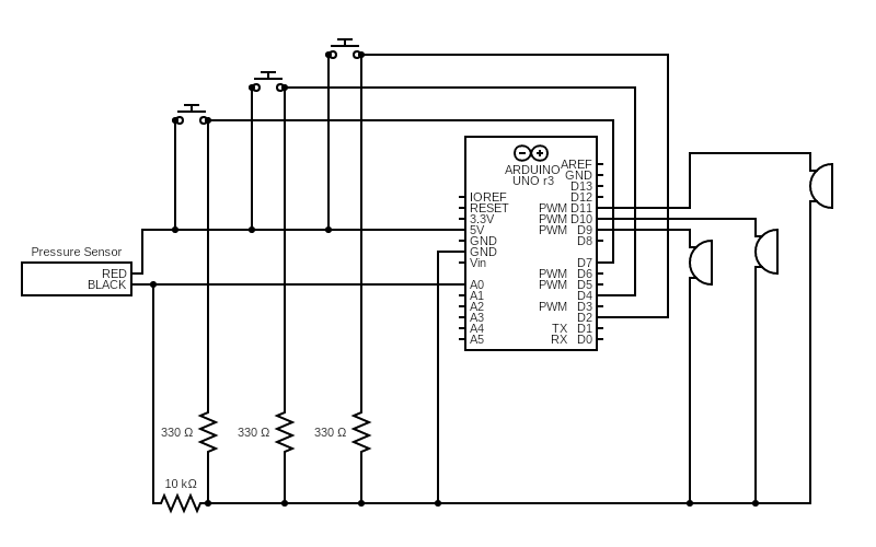
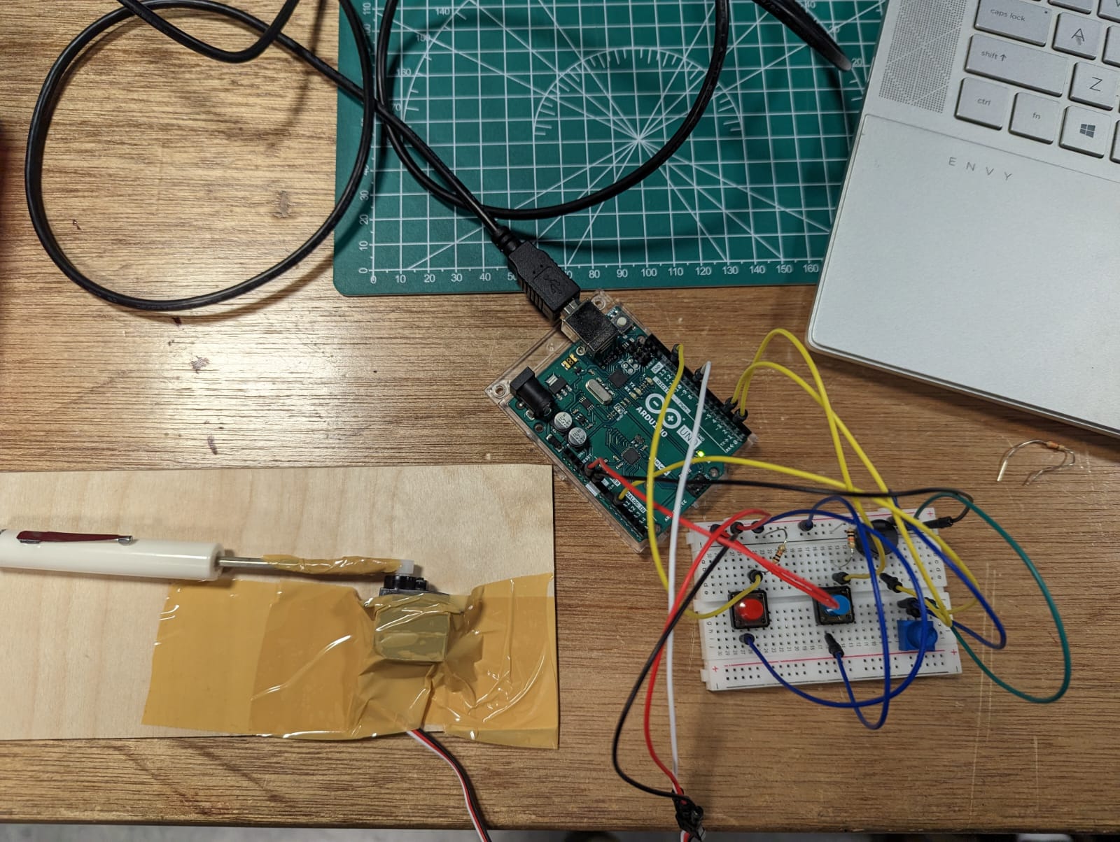
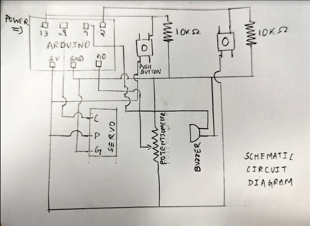
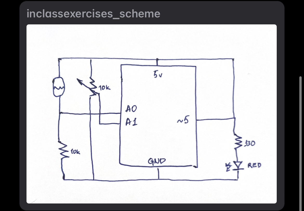
We decided to start off with a button (red colored) that was solely for the purposes of changing, or flipping through the different modes of the composer. Then, there would be a Piezo Buzzer that produced sound, but controlled by 2 additional Buttons and a Potentiometer, alongside a Servo Motor which would act as a Drum Stick.
Since Arduino does not have any specific mode for switching ‘off’, we decided to have the first mode as an ‘inactive’ state. Then, when the button is pressed, it becomes a music player which plays Melodies that can be essentially changed by the potentiometer. For this, the values of the Potentiometer are mapped to a range of 100-1000, and then there are ‘if’ conditions to check if it is between certain ranges, and so corresponding music would play.
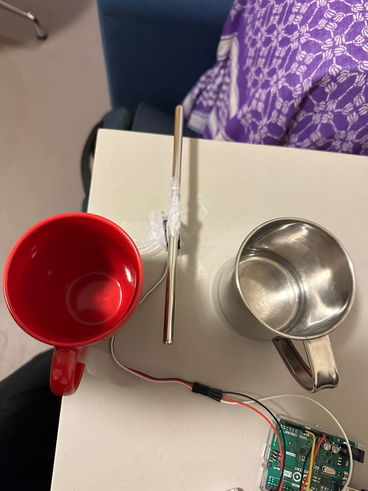
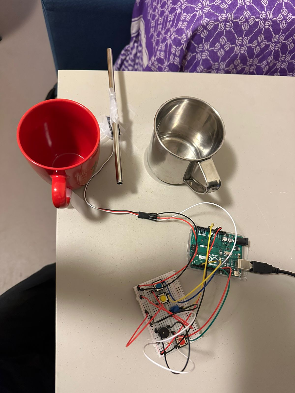
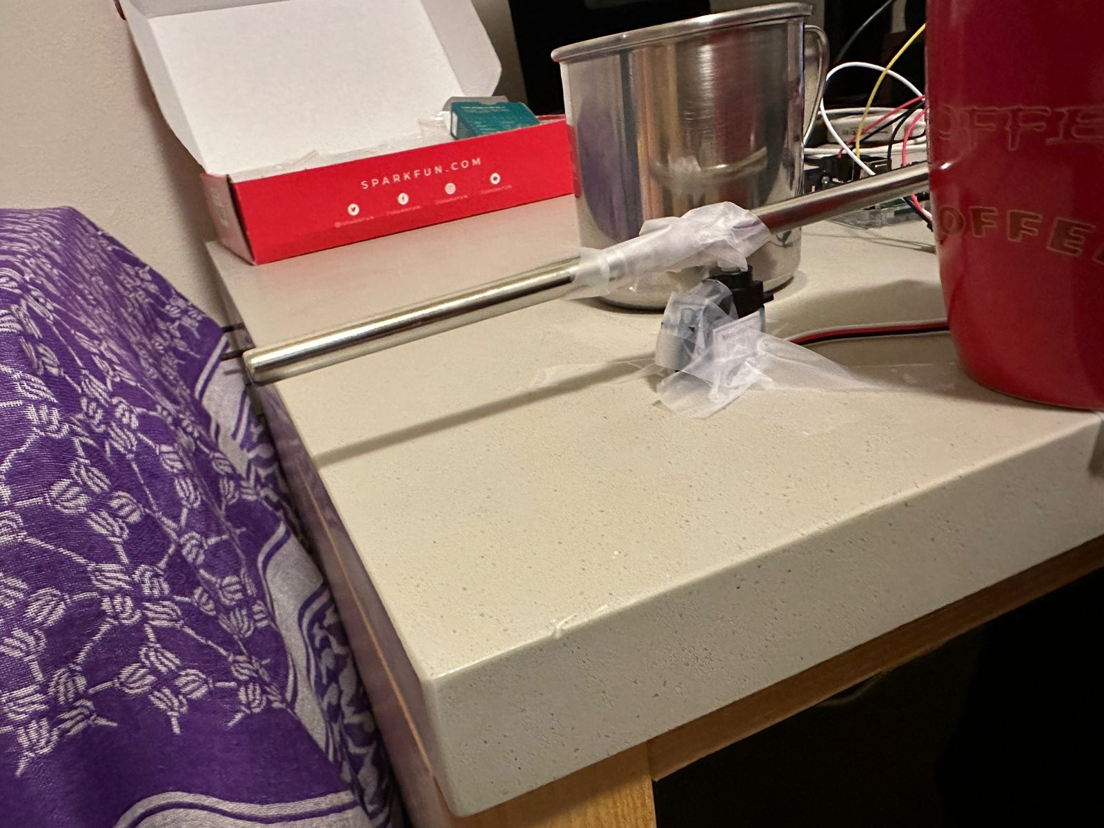
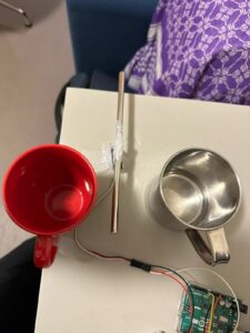
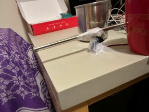
Moving forward, our next mode, the Creative Mode, is very intriguing. It activates the Servo Motor to function as a Drum Stick, and in our case, instead of drums, we utilized a steel mug and a ceramic mug to produce sounds of different quality and pitch. The other two buttons in our circuit would be controlling the direction of the stick, whether it would hit the ceramic, or the steel mug. On top of this, in this mode, the Potentiometer would have its Analog Values mapped to multiples of 50 in the range from 100-1000, and would subsequently have the capacity to produce additional sounds, adding some composure.
The last mode, is the Piano Mode, where the Two Buttons would simply act as Keyboard Keys, and would be limited to produce two types of sounds. However, the Potentiometer would essentially fluctuate these values using a formula. With this, we could fluctuate the Potentiometer like a Mixer and use the two buttons as keys to produce interesting continuous sounds.
With this, we have demonstrated how only the usage of 2 buttons, a Piezo Buzzer and a Potentiometer can be used in different permutations and produce varying types of sounds. The flexibility offered by the Arduino with a breadboard offers limitless opportunities.
Demo Video
A demo video, in detail, can be seen here:
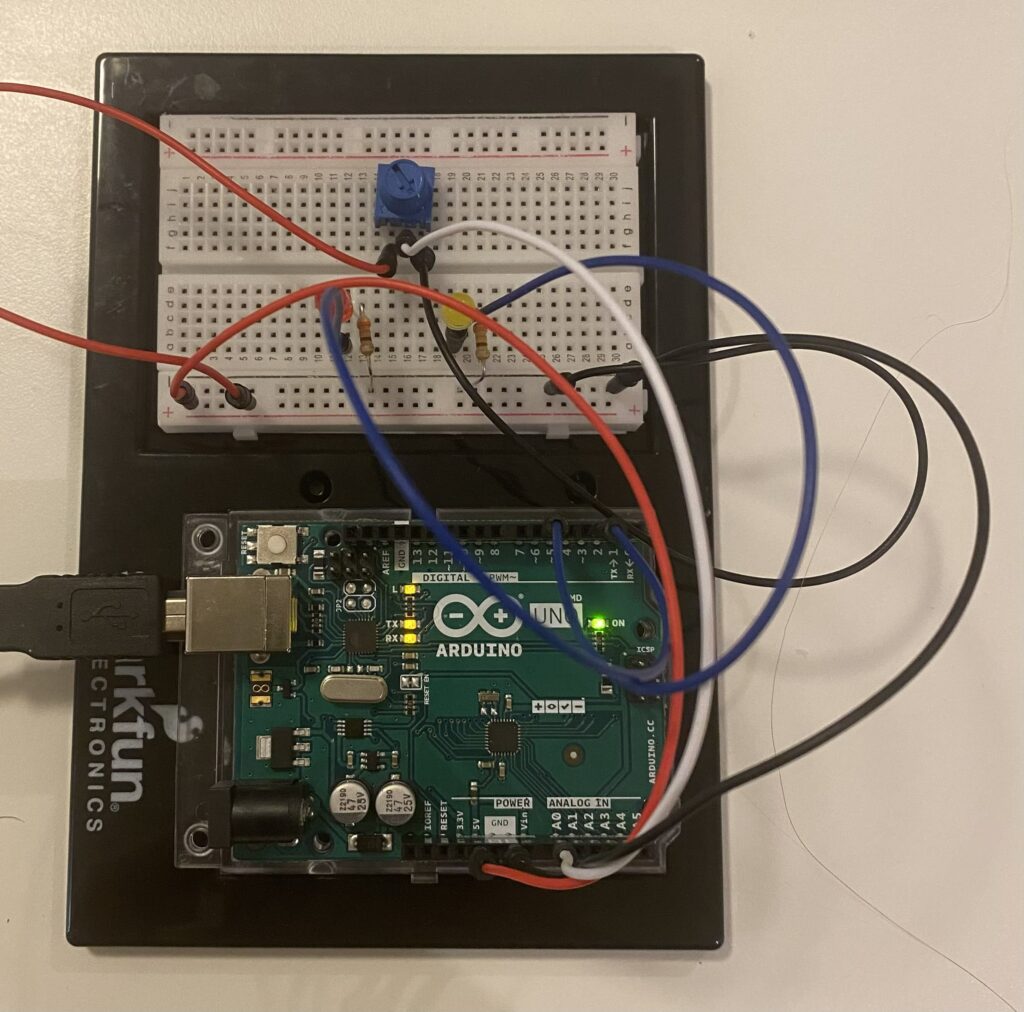
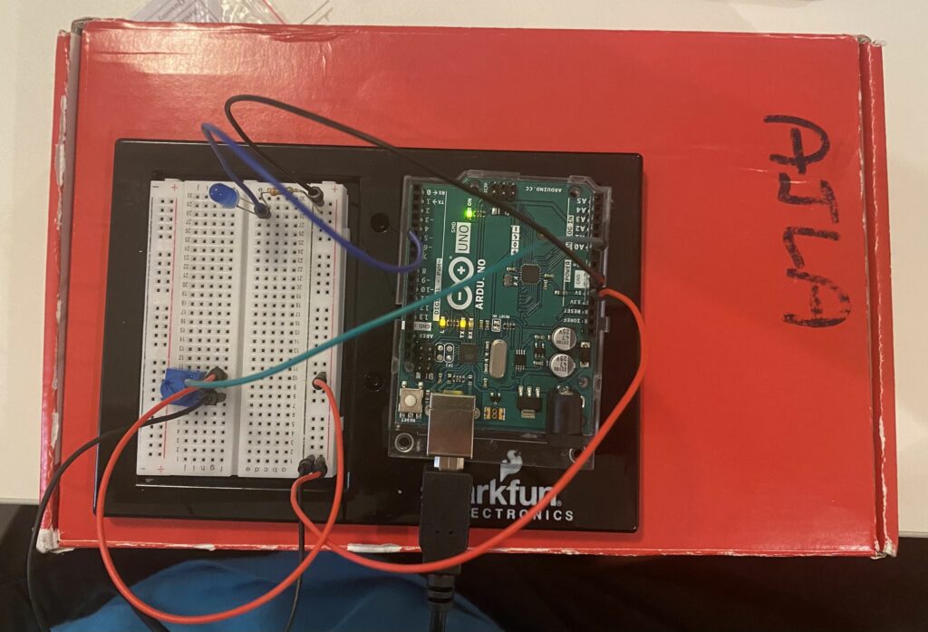
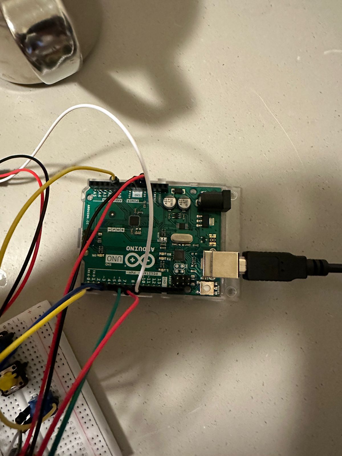
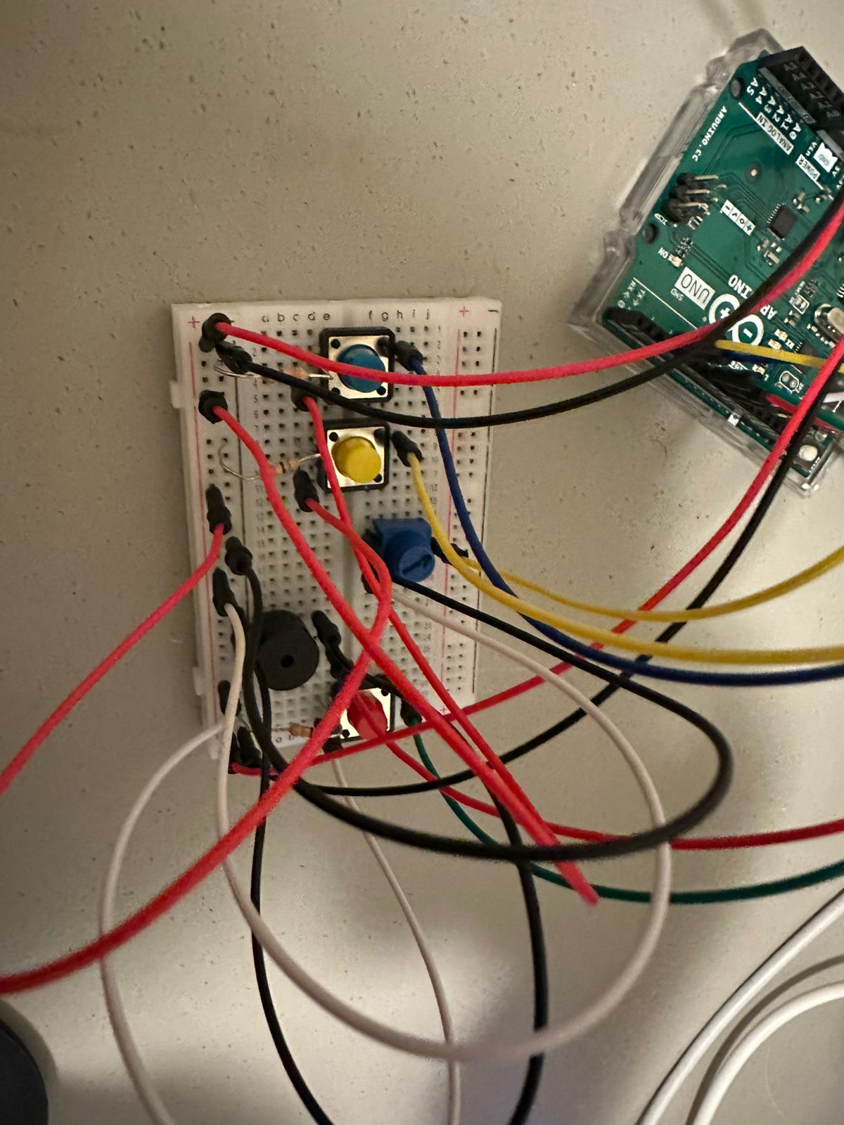
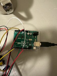
Pictures of Circuit

Difficulties
The first difficulty that we faced was to replace the traditional usage of ‘delays’ to be replaced with a consistently running timer. This was particularly in the first mode, the music player mode, wherein we would have to switch to another mode by pressing the red button, however having pressed that during a delay would have caused issue. We catered to this using one of the Arduino’s standard examples of ‘BlinkWithoutDelay’ and utilized the millis() function to keep a track of time on our own.
Moreover, the project was becoming a complex state machine, and difficult to manage. We wanted to add more buttons for the Piano, however there was a choice between going for a complex looking and difficult to manage circuit, or actually utilizing minimal equipment in creative ways.
Being new to Arduino, we initially thought of keeping loose wires, instead of buttons, which would trigger the piano notes. However, after spending hours of trying out ways with which we would have loose pins connected to the arduino where a connection would play a not, we improvised the usage of the same buttons to play the notes.
Improvements
With such a project, the perception becomes very subjective with multiple ways of improvement. However, something that we definitely see is making the project more easy to use and adding more options in each stage. More melodies in the first mode, more options to create in the second mode, and more piano buttons in the third mode.
Code
Specific Segments
Starting off with the General State Machine, we have used the click of a button, tracked by a previous state and a current state which calculates if there is a change in the state of button (when its pressed again, not held). Once a change occurs, the value of the button state is set such that an appropriate mode is switched on:
// To change the MODES of the Instrument
if(lastredButtonState == HIGH && currentredButtonState == LOW) {
  Serial.print("RED Button is pressed: ");

  Serial.println(redButtonState);

  // Change the state of LED
  if(redButtonState == 0) {
    redButtonState = 1;
    Serial.println("Opening the Infinite Playing Mode");
  }
  else if (redButtonState == 1){
    redButtonState = 2;
    Serial.println("Changing to the Creative Mode");
  }
  else if (redButtonState == 2){
    redButtonState = 3;
    Serial.println("Changing to the Piano Mode");
  }
  else{
    redButtonState = 0;
    Serial.println("Switching the Instrument off");
  }
}
When a button state is set, there is another condition in the loop() function which repeatedly checks if that mode is switched on. In the case that the state is 1, we have to play music of two different melodies depending on the potentiometer’s value. However, the important thing is to ensure we dont use delays since we could be changing the mode while the music is playing, and do not want to have to wait.
Therefore, the following piece of code makes use of the millis() function and keeps track of an internal timer.
if (redButtonState == 1){
  // Beginning of an Infinite Playing Mode
  val = map(val, 0, 1023, 100, 1000);     // scale it for use with the servo (value between 0 and 180)

  currentMillis = millis();
  if (currentMillis - previousMillis >= noteDuration + pauseBetweenNotes) {
    previousMillis = currentMillis;
    // stop the previous note
    noTone(8);

    if (val>450){
      // play the next note
      noteDuration = 1000 / noteDurations[noteIndex];
      tone(8, melody[noteIndex], noteDuration);
      pauseBetweenNotes = noteDuration * 0.30;
      // move to the next note
      noteIndex = (noteIndex + 1) % melodyLength;
    }
    else{
      // play the next note
      noteDuration = 1000 / noteDurations2[noteIndex];
      tone(8, melody2[noteIndex], noteDuration);
      pauseBetweenNotes = noteDuration * 0.30;
      // move to the next note
      noteIndex = (noteIndex + 1) % melodyLength2;
    }

  }
  // add a small delay to avoid overloading the processor
  delay(1);
  // End of the Infinite Playing Mode
}
For our creative mode, we simply move the motor in the specified directions with the following code, alongside playing a continuous tone that just varies with the value of the potentiometer.
else if (redButtonState == 2){
  // Serial.println("Creative Mode");
// BEGINNING OF CREATIVE MODE

  // check if the pushbutton is pressed. If it is, the buttonState is HIGH:
  if (yelButtonState == HIGH) {
    // print out the value you read:
    Serial.println("YELLOW PRESSED");
    myservo.write(180);
  }
  else if (bluButtonState == HIGH)
  {
    // print out the value you read:
    Serial.println("NOT YELLOW");
    myservo.write(0);
  }
  else
  {
    myservo.write(90);
  }

  val = map(val, 0, 1023, 100, 1000);     // scale it for use with the servo (value between 0 and 180)
  val = 50 * ((val + 49) / 50);
  if(val>250){
    tone(8, val, 200);
  }

// END OF CREATIVE MODE
}
Overall Code
While the specific segments are highlighted above, the entire code may give more insights of the project:
/*
  Musical Instrument
  Created 10 April, 2023
  by Ishmal Khalid and Zunair Viqar
*/

#include <Servo.h>
#include "pitches.h"

int melody[] = {
  // Pink Panther theme
  // Score available at https://musescore.com/benedictsong/the-pink-panther
  // Theme by Masato Nakamura, arranged by Teddy Mason
  REST, REST, REST, NOTE_DS4,
  NOTE_E4, REST, NOTE_FS4, NOTE_G4, REST, NOTE_DS4,
  NOTE_E4, NOTE_FS4,  NOTE_G4, NOTE_C5, NOTE_B4, NOTE_E4, NOTE_G4, NOTE_B4,
  NOTE_AS4, NOTE_A4, NOTE_G4, NOTE_E4, NOTE_D4,
  NOTE_E4, REST, REST, NOTE_DS4,

  NOTE_E4, REST, NOTE_FS4, NOTE_G4, REST, NOTE_DS4,
  NOTE_E4, NOTE_FS4, NOTE_G4, NOTE_C5, NOTE_B4, NOTE_G4, NOTE_B4, NOTE_E5,
  NOTE_DS5,
  NOTE_D5, REST, REST, NOTE_DS4,
  NOTE_E4, REST, NOTE_FS4, NOTE_G4, REST, NOTE_DS4,
  NOTE_E4, NOTE_FS4, NOTE_G4, NOTE_C5, NOTE_B4, NOTE_E4, NOTE_G4, NOTE_B4,

  NOTE_AS4, NOTE_A4, NOTE_G4, NOTE_E4, NOTE_D4,
  NOTE_E4, REST,
  REST, NOTE_E5, NOTE_D5, NOTE_B4, NOTE_A4, NOTE_G4, NOTE_E4,
  NOTE_AS4, NOTE_A4, NOTE_AS4, NOTE_A4, NOTE_AS4,NOTE_A4,NOTE_AS4,NOTE_A4,
  NOTE_G4, NOTE_E4, NOTE_D4, NOTE_E4, NOTE_E4, NOTE_E4
};

int noteDurations[] = {
  // Pink Panther theme
  // Score available at https://musescore.com/benedictsong/the-pink-panther
  // Theme by Masato Nakamura, arranged by Teddy Mason
  2,4,8,8,
  4 ,8,8,4,8,8,
  8 ,8, 8,8,8,8,8,8,
  2 ,16,16,16,16,
  2 ,4,8,4,

  4,8,8,4,8,8,
  8,8,8,8,8,8,8,8,
  1,
  2,4,8,8,
  4,8,8,4,8,8,
  8,8, 8,8,8,8,8,8,

  2,16,16,16,16,
  4,4,
  4,8,8,8,8,8,8,
  16,8,16,8,16,8,16,8,
  16,16,16,16,16,2
};

// notes in the melody:
int melody2[] = {
  NOTE_C4, NOTE_G3, NOTE_G3, NOTE_A3, NOTE_G3, 0, NOTE_B3, NOTE_C4
};

// note durations: 4 = quarter note, 8 = eighth note, etc.:
int noteDurations2[] = {
  4, 8, 8, 4, 4, 4, 4, 4
};

Servo myservo;  // create servo object to control a servo
// constants won't change. They're used here to set pin numbers:
const int yelButtonPin = 2;  // the number of the yellow pushbutton pin
const int bluButtonPin = 4;    // the number of the blue pushbutton pin
const int redButtonPin = 7;    // the number of the red pushbutton pin
const int LIGHT_SENSOR_PIN = A0;

// variables will change:
int yelButtonState = 0;  // variable for reading the pushbutton status
int bluButtonState = 0;
int redButtonState = 0;
int lastredButtonState; // the previous state of the light button
int currentredButtonState; // the current state of the light button

int potpin = A0;  // analog pin used to connect the potentiometer
int val;    // variable to read the value from the analog pin
int val2;  // variable to map the val value to the piano
int pos = 90;    // variable to store the servo position

// Declarations for playing the melodies, without using delay
unsigned long currentMillis = 0;
unsigned long previousMillis = 0;  // will store last time LED was updated
int noteDuration = 0; // Duration of each note to be played, taken from the array
int pauseBetweenNotes = 0; // duration between notes - arbitrary
int noteIndex = 0; // Keeping track of the note to play since we dont use for loop
// The lengths of each Melody
int melodyLength = sizeof(melody) / sizeof(int);
int melodyLength2 = sizeof(melody2) / sizeof(int);

void setup() {
  myservo.attach(9);  // attaches the servo on pin 9 to the servo object

  // initialize the pushbutton pin as an input:
  pinMode(yelButtonPin, INPUT);
  // initialize the pushbutton pin as an input:
  pinMode(bluButtonPin, INPUT);
  // initialize the pushbutton pin as an input:
  pinMode(redButtonPin, INPUT);

  currentredButtonState = digitalRead(redButtonPin);

  // initialize the tone library
  pinMode(8, OUTPUT);

  // initialize serial communication at 9600 bits per second:
  Serial.begin(9600);
}

void loop() {
  lastredButtonState  = currentredButtonState; // Store Previous State of the light button
  currentredButtonState = digitalRead(redButtonPin); // Get new state of the light button

  // read the state of the yellow pushbutton value:
  yelButtonState = digitalRead(yelButtonPin);
  // read the state of the blue pushbutton value:
  bluButtonState = digitalRead(bluButtonPin);

  val = analogRead(potpin);            // reads the value of the potentiometer (value between 0 and 1023)
  val2 = map(val, 0, 1023, 50, 5000);     // scale it for use with the servo (value between 0 and 180)

  // To change the MODES of the Instrument
  if(lastredButtonState == HIGH && currentredButtonState == LOW) {
    Serial.print("RED Button is pressed: ");

    Serial.println(redButtonState);

    // Change the state of LED
    if(redButtonState == 0) {
      redButtonState = 1;
      Serial.println("Opening the Infinite Playing Mode");
    }
    else if (redButtonState == 1){
      redButtonState = 2;
      Serial.println("Changing to the Creative Mode");
    }
    else if (redButtonState == 2){
      redButtonState = 3;
      Serial.println("Changing to the Piano Mode");
    }
    else{
      redButtonState = 0;
      Serial.println("Switching the Instrument off");
    }
  }

  if (redButtonState == 1){
    // Beginning of an Infinite Playing Mode
    val = map(val, 0, 1023, 100, 1000);     // scale it for use with the servo (value between 0 and 180)

    currentMillis = millis();
    if (currentMillis - previousMillis >= noteDuration + pauseBetweenNotes) {
      previousMillis = currentMillis;
      // stop the previous note
      noTone(8);

      if (val>450){
        // play the next note
        noteDuration = 1000 / noteDurations[noteIndex];
        tone(8, melody[noteIndex], noteDuration);
        pauseBetweenNotes = noteDuration * 0.30;
        // move to the next note
        noteIndex = (noteIndex + 1) % melodyLength;
      }
      else{
        // play the next note
        noteDuration = 1000 / noteDurations2[noteIndex];
        tone(8, melody2[noteIndex], noteDuration);
        pauseBetweenNotes = noteDuration * 0.30;
        // move to the next note
        noteIndex = (noteIndex + 1) % melodyLength2;
      }

    }
    // add a small delay to avoid overloading the processor
    delay(1);
    // End of the Infinite Playing Mode
  }
  else if (redButtonState == 2){
    // Serial.println("Creative Mode");
  // BEGINNING OF CREATIVE MODE

    // check if the pushbutton is pressed. If it is, the buttonState is HIGH:
    if (yelButtonState == HIGH) {
      // Moves the motor in the one direction
      Serial.println("YELLOW PRESSED");
      myservo.write(180);
    }
    else if (bluButtonState == HIGH)
    {
      // Moves the motor to the other direction
      Serial.println("NOT YELLOW");
      myservo.write(0);
    }
    else
    {
      // otherwise brings the motor to the center
      myservo.write(90);
    }
    // Maps the value read from the Analog Sensor
    val = map(val, 0, 1023, 100, 1000);     // scale it for use (value between 100 and 1000)
    // Takes multiples of 50s only, this is used since we needed distinguishable notes, not a linear shift in the notes.
    val = 50 * ((val + 49) / 50);
    // Allows us to switch the Potentiometer notes to be 'off'
    if(val>250){
      tone(8, val, 200);
    }

  // END OF CREATIVE MODE
  }
  else if (redButtonState == 3){
    // Serial.println("Add Piano Mode");
  // BEGINNING OF PIANO MODE
    // The yellow button tone played in the PIANO Mode
    if (yelButtonState == HIGH) {
      tone(8, 4000-val2, 5); // the 4000-val2 was done by trial and error to reach a value that varies
    }
    // The blue button tone played in the PIANO Mode
    else if (bluButtonState == HIGH)
    {
      tone(8, 1000+val2, 5); // the 1000+val2 was done by trial and error to reach a value that varies
    }


  // END OF PIANO MODE
  }
  else if (redButtonState == 0){
    Serial.println("Switched Off");
  }
}

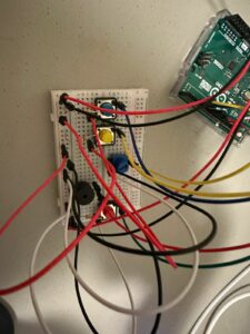
 Picture of the circuit (The LEDs are used to check the wiring):