Concept & Method
In this assignment, I am using two LEDs, one switch (digital), and one slider potentiometer (analog). The switch controls the entire circuit, and the potentiometer controls the brightness of the LEDs.
Implementation
Code:
#define LED_PIN 3
#define BUTTON_PIN 7
#define POTENTIO_PIN A1

byte lastButtonState = HIGH;
bool LEDOn = true;

void setup()
{
  pinMode(LED_PIN, OUTPUT);
  pinMode(BUTTON_PIN, INPUT_PULLUP);
}

void loop()
{
    byte buttonState = digitalRead(BUTTON_PIN);
    if (buttonState != lastButtonState)
    {
      lastButtonState = buttonState;

      if (buttonState == HIGH) { // button has been released
        LEDOn = ! LEDOn;
      }
   }

  if (LEDOn) {
    int potentiometerValue = analogRead(POTENTIO_PIN);
    int brightness = map(potentiometerValue, 0, 1023, 0, 255);

    analogWrite(LED_PIN, brightness);
    delay(100);                      // delay is in milliseconds
    analogWrite(LED_PIN, LOW);       // turn LED off (0V)
    delay(100);
  }
  else {
    digitalWrite(LED_PIN, LOW);
  }
}
For this assignment, I used two LEDs controlled by two switches. The idea is that when one switch is pressed, one of the lights turns on and the other one turns off. When the other button is pressed, the light that is on turns off, and the one controlled by that switch is turned on. When both the buttons are pressed at the same time, both lights blink.
Code
void setup() {
  pinMode(8, OUTPUT);
  pinMode(13, OUTPUT);
  pinMode(A2, INPUT);
  pinMode(A3, INPUT);

digitalWrite(13, LOW);
digitalWrite(8, LOW);

}

void loop() {

  int switchPosition = digitalRead(A2);
  int switchTwoPosition = digitalRead(A3);

  if (switchPosition == HIGH && switchTwoPosition == HIGH)
  {
    digitalWrite(13, HIGH);
    digitalWrite(8, HIGH);
    delay(100);
    digitalWrite(13, LOW);
    digitalWrite(8, LOW);
    delay(100);

  }
  else
  {
    if (switchPosition == HIGH) {
    digitalWrite(13, HIGH);
    digitalWrite(8, LOW);

  }

  if (switchTwoPosition==HIGH)
  {
    digitalWrite(8, HIGH); // turn the LED on (HIGH is the voltage level)
    digitalWrite(13, LOW);
  }

  }

}
Video
Future Improvements
Later, I can add more layers to the lights when each button is separately pressed, for example, change the brightness of the lights or make them fade.
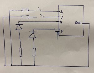
Concept: For this project I wanted to create the flashing lights of police cars. Using the two buttons the user can either turn on the red LED or the blue one. While when both buttons are pressed both LEDs starting flashing rapidly creating the same visual effect as a police car or an ambulance.
Equipment: In this project I have used two red and blue LEDS, two push buttons, 4 resistors. Using the resistors is important not to just protect the LEDS but also they are necessary to protect the Arduino board and avoid creating a short circuit between the button, the pins 3 and 4 and ground.
Utilizing 2 analog sensors, I created a double switch system with the LEDs and created flashing lights similar to what you might find in a disco!
I drew this rough schematic on my phone in order to get an understanding of how the power would move throughout my circuit. I had to make sure that the LEDs receive sufficient power as to not make their outputs too dull. After drawing the schematic, I created the circuit trying my best to keep it somewhat neat as to be able to quickly identify which wires leads to where. After that, I wrote down the code in order to bring the disco to life which you can find below:
All this hard work combined led to the final product below:
For future imrpovements, I can add more LEDs in order to further the feel of a disco. I can also add some variation in how the LEDs blink or how long they stay on or how bright they should be!
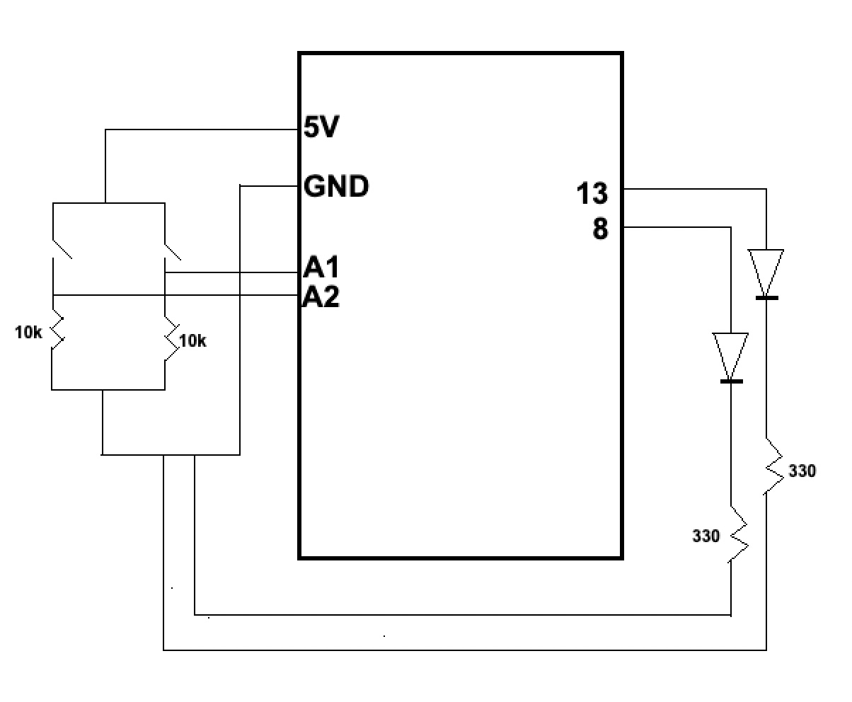
For this assignment, I wanted to simulate police lights so I used two LEDs (blue and red) and two push (button switches). Each switch turns on the respectively colored LED, and when both switches are pressed the LEDs blink continuously looking like police lights.
Schematic
Code
//Declare the button switches and the LEDs
const int BUTTON1 = 2;
const int BUTTON2 = 5;
const int LED1 = 8;
const int LED2 = 12;
int BUTTONstate1 = 0;
int BUTTONstate2 = 0;

void setup()
{
//Declare the buttons as input and the LEDs as output
pinMode(BUTTON1, INPUT);
pinMode(BUTTON2, INPUT);
pinMode(LED1, OUTPUT);
pinMode(LED2, OUTPUT);
}

void loop()
{
// Turn on the blue LED by pressing the blue switch
BUTTONstate1 = digitalRead(BUTTON1);
if (BUTTONstate1 == HIGH)
{
digitalWrite(LED1, HIGH);
}
else{
digitalWrite(LED1, LOW);
}
//Turn on the Red LED by pressing the red switch
BUTTONstate2 = digitalRead(BUTTON2);
if (BUTTONstate2 == HIGH)
{
digitalWrite(LED2, HIGH);
}
else
{
digitalWrite(LED2, LOW);
}
//Blink the two LEDs when the two switches are pressed
if (BUTTONstate1 == HIGH && BUTTONstate2 == HIGH){
digitalWrite (LED1, HIGH);
digitalWrite (LED2, LOW);
delay(750);  // Wait 750ms
digitalWrite (LED1, LOW);
digitalWrite (LED2, HIGH);
delay(500);  // Wait 500ms
}
}
Video
Future Improvements
In the future, I would like to experiment with a greater number of LEDs. Additionally, I would like to implement analog switches such as the potentiometer next.
While I really like sunlight or natural light filtering in through my window, if I am deeply focused on a task I often forget to turn the lights on when the sun has set and this has often lead to headaches and dryness in my eyes due to eye strain when working on my laptop in the dark. So I wanted to create an indicator using a light sensor and LED in which the LED starts to blink if the light in the room is very dim. The glaring red alarm LED can only be temporarily switched to a blue light when a button is pressed down because I often get lazy and don’t get up to turn on the lights. So the red light would continue to blink as long as lights are not turned on and it becomes brighter in the room.
Circuit
I created the following circuit for the light indicator. I connected the LDR with a pull down resistor of 10K Ω and in the same circuit added the red LED with its respective resistor of 330Ω. Then I connected the red LED and LDR with the blue LED through a button and following is the Arduino Uno code for the circuit:
const int BUTTON = 7; // the number of the pushbutton pin on the arduino board
int lastState = LOW; // the last state from the button
int currentState;    // the current reading from the button
const int LIGHT_SENSOR_PIN = A0;
const int LED_PIN          = 3;
const int LED_PIN_2          = 11;
const int ANALOG_THRESHOLD = 500;
int Analog;

void setup() {
  Serial.begin(9600);
  pinMode(LED_PIN, OUTPUT);

  pinMode(BUTTON, INPUT_PULLUP);
}

void loop() {
  Analog = analogRead(LIGHT_SENSOR_PIN); // read the input on LDR

  currentState = digitalRead(BUTTON); //read input on button
  if(Analog < ANALOG_THRESHOLD){
    if (currentState==HIGH){
      digitalWrite(LED_PIN, HIGH);   // turn LED on
      delay(500);                       // wait
      digitalWrite(LED_PIN, LOW);    // turn LED off
      delay(500);
    }
    else{
      digitalWrite(LED_PIN_2, HIGH);   // turn LED
      delay(500);                       // wait
      digitalWrite(LED_PIN_2, LOW);    // turn LED off
      delay(500);
    }

  }
  else{
    digitalWrite(LED_PIN, LOW);  // turn LED off
  }


}
Improvements
For future improvements I would want to add some sort of sound alarm to it as well so that I do not ignore the indicator at all because of the noise. I would also like to add a LED that starts blinking again after a set time period of the lights are not turned on in for example 5 minutes or something similar to this.
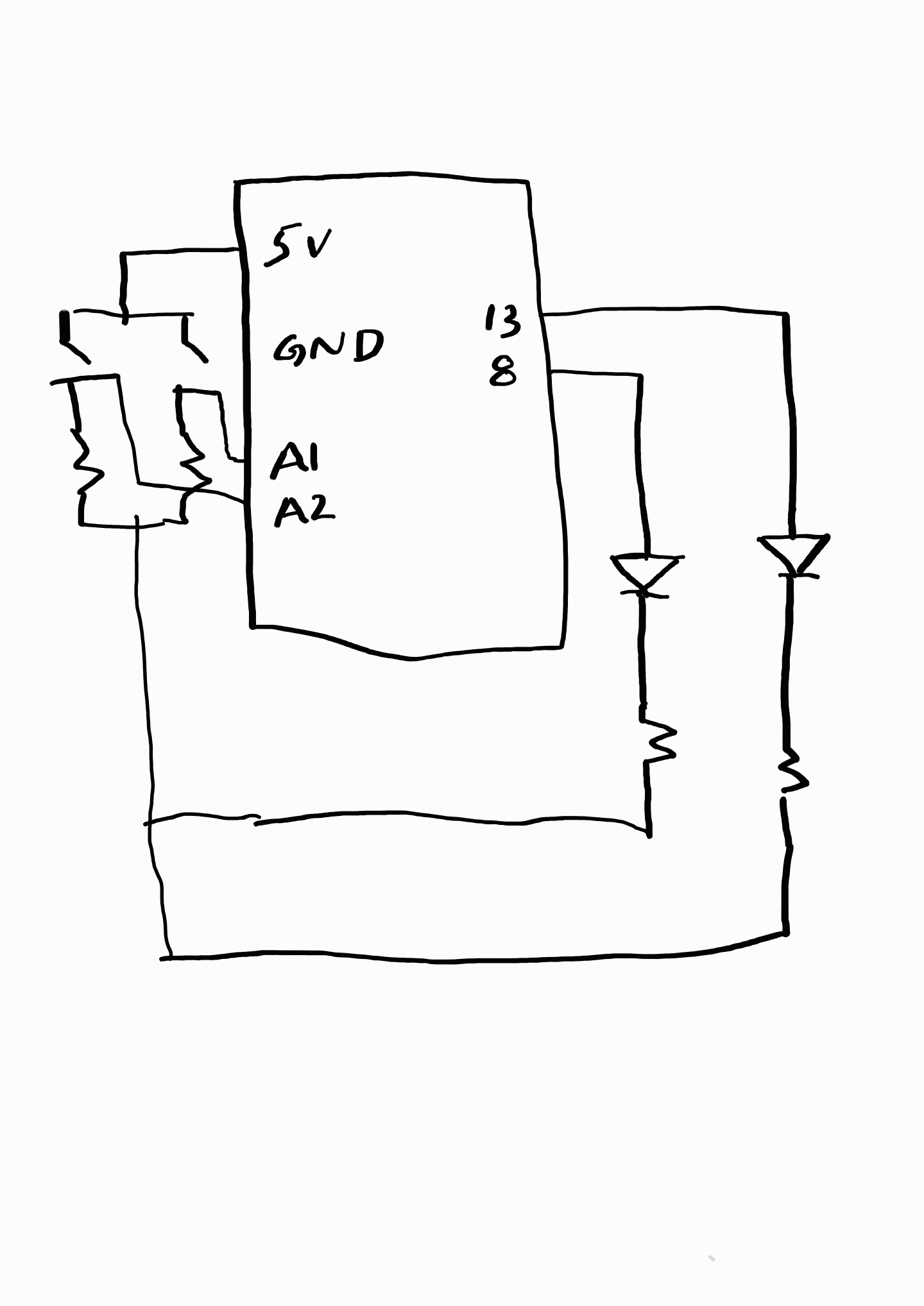
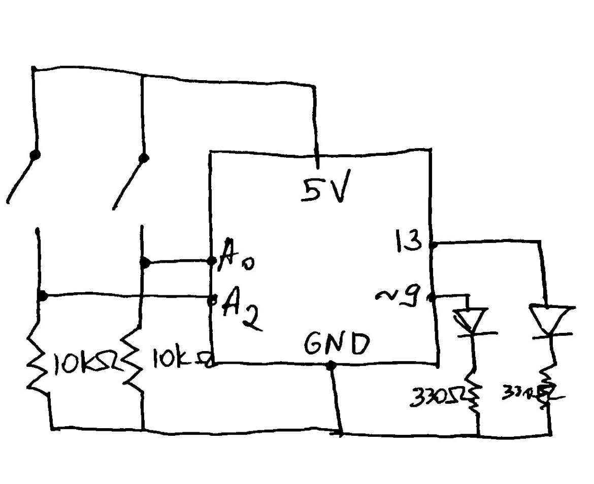
For my digital sensors assignment, I used the sun and the moon as an inspiration. I used a yellow LED to represent the sun and a blue LED to represent the moon.
Implementation:
When the yellow button is pressed, the yellow LED – a.k.a. the Sun – lights up and when the blue button is pressed, the blue LED – a.k.a. the moon – lights up. When both buttons are pressed at the same time, they each blink and alternate for 1 second with an interval of 0.5 seconds, representing the cycle of the sun and the moon.
Circuit schematics:
Video:
Code:
int yellowLED = 13; //labeling the digital output for the yellow LED
int blueLED = 9; //labeling the digital output for the blue LED

void setup() {
  pinMode(yellowLED, OUTPUT);
  pinMode(blueLED, OUTPUT);
  pinMode(A0, INPUT);
  pinMode(A2, INPUT);
}

void loop(){

  int switchPositionYellow = digitalRead(A0);
  int switchPositionBlue = digitalRead(A2);

  if (switchPositionYellow == HIGH) { //if the yellow button is pressed, the yellow LED is turned on
    digitalWrite(yellowLED, HIGH);
    digitalWrite(blueLED, LOW);
  }

  else if (switchPositionBlue == HIGH) { // if the blue button is pressed, the blue LED is turned on
    digitalWrite(yellowLED, LOW);
    digitalWrite(blueLED, HIGH);
  }

  else {
    digitalWrite(yellowLED, LOW); //if both buttons aren't pressed, the LEDs are turned off
    digitalWrite(blueLED, LOW);
  }

  if (switchPositionYellow == HIGH && switchPositionBlue == HIGH) { //if both buttons are pressed,
                                                                    //both LEDS will blink and will alternate
    digitalWrite(yellowLED, HIGH);
    delay(1000);
    digitalWrite(yellowLED, LOW);
    delay(500);

    digitalWrite(blueLED, HIGH);
    delay(1000);
    digitalWrite(blueLED, LOW);
    delay(500);
  }
}
Future Improvements:
In the future, I want to uphold and develop the concept Moresby including an analog sensor that detects light. When the light shines, “the sun” – yellow LED – would turn on, and when the light does not shine, “the moon” – blue LED – would turn on.
Since we didn’t have enough time in class to go over the analog sensor, I kept my in class activity project using two digital sensors, the buttons, to have different outputs per button and a completely different output for pressing both buttons.
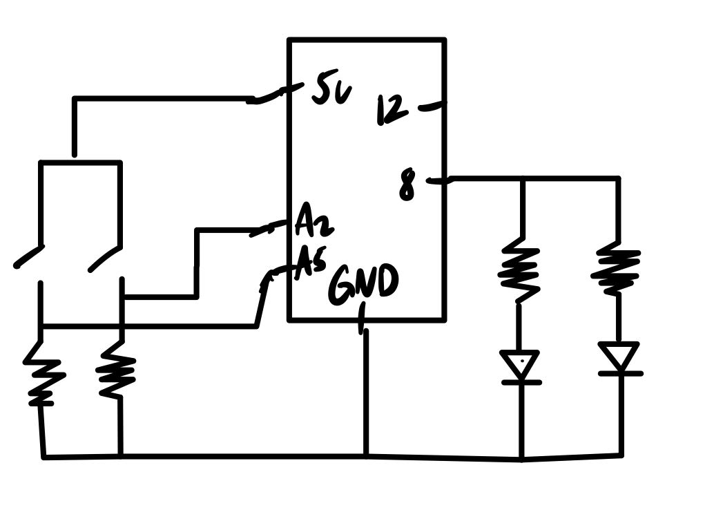
Project
For my circuit, I had two buttons each connected to a resistor and a input slot A2 and A5 where if one of the buttons are pressed, the correlating LED light will blink in an 500 delay interval. If the button is released, then the light will stop blinking. If both of the buttons are pressed, then both lights will blink at 100 delay interval.
Initially I was trying to have the buttons as a trigger to a function that will continue in a loop so that the lights will keep blinking if I pressed the button once and will stop blinking if I pressed it again. However, since I was not so proficient with arduino yet, I failed to achieve the effect. I think this could be an improvement I could work on for future practices.
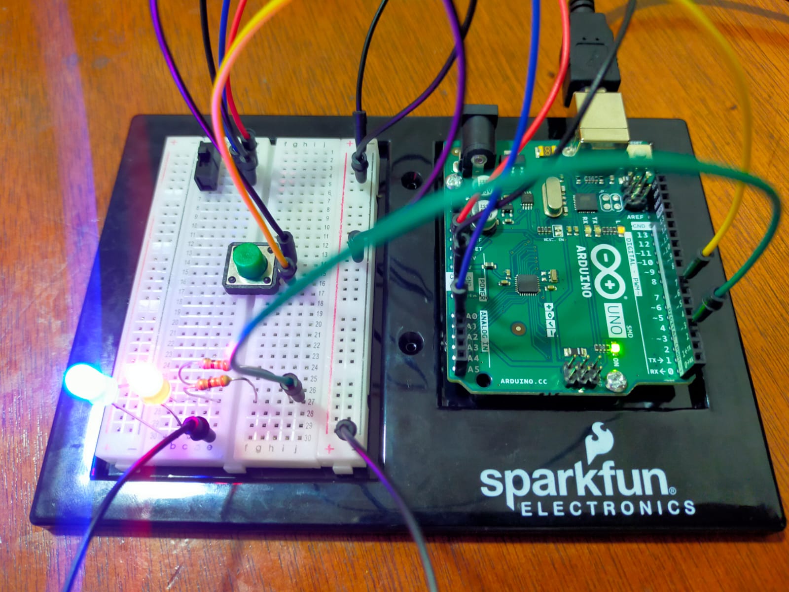
While brainstorming with my roommate about what to make for this week’s assignment, my suitemate arrived and expressed his frustration about our friends constantly knocking on our door when we’re not there. He complained about the disturbance, particularly during exams and at night. While apologizing to him, an idea popped into my head – a solution that would inform our friends about our availability. The concept involves two LEDs outside our room representing my roommate and me, which will turn on when we’re in the room and off when we’re not. If neither of us are in the room, we can press the two buttons together before leaving, causing the lights to flicker, indicating that we are not available. This solution could potentially address the problem for our friends and our suitemate.
Implementation:
To help navigate the board, I first drew the circuit diagram so that I would know what component would go where. To make my life easier, I used the red wire for 5V, black wire for GND, green wire for the green button, yellow wire for yellow button and the two white wires for the two LEDs. The circuit diagram looks like this:
I did run into a few problems with the code where pushing the button for a relatively longer period would reverse the effect that I wanted. I then added delay in certain places to resolve this issue. The code looks like this:
//globally declaring the three variables. Setting them to 1 so that all the lights are off
int yellowCount = 1;
int greenCount = 1;
int doubleCount = 1;

void setup() {
  //setting pinmodes. 8 and 13 as output since they are connected to the LEDs
  pinMode(8, OUTPUT);
  pinMode(13, OUTPUT);
  pinMode(A2, INPUT); //A1 and A2 as input for the switches
  pinMode(A1, INPUT);
}

void loop() {
  int yellowSwitch = digitalRead(A2); //read the yellow switch
  delay(100);
  int greenSwitch = digitalRead(A1);
  delay(100);

  if (greenSwitch == HIGH && yellowSwitch == HIGH) //when both the switches are pressed together
  {
    doubleCount = doubleCount + 1; //increment this counter

  }
  else
  {
    if (yellowSwitch == HIGH) //for individual switches, increment their respective counters
    {
      yellowCount = yellowCount + 1;
    }

    if (greenSwitch == HIGH)
    {
      greenCount = greenCount + 1;
    }
  }

  if (doubleCount % 2 == 0) //if the counter is even
  {
    digitalWrite(8, HIGH);  //high for one
    digitalWrite(13, LOW); //low for the other
    delay(150); //wait
    digitalWrite(8, LOW); //then invert the voltages
    digitalWrite(13, HIGH); //to give off a flickering effect
    delay(150);

    yellowSwitch = digitalRead(A2); //read the two again
    greenSwitch = digitalRead(A1);

    if (yellowSwitch == HIGH) //if one of them is pressed
    {
      doubleCount = doubleCount + 1; //then this values goes to odd and then the flickering stops
    }

    if (greenSwitch == HIGH)
    {
      doubleCount = doubleCount + 1;
    }

  }
  else
  {
    if (yellowCount % 2 == 0) //if the yellow is pressed again and the count is even
    {
      digitalWrite(8, HIGH); //turn on the led
    }
    else
    {
      digitalWrite(8, LOW); //otherwise turn it off
    }

    if (greenCount % 2 == 0) //same for the green button
    {
      digitalWrite(13, HIGH);
    }
    else
    {
      digitalWrite(13, LOW);
    }
  }
}
The final implementation looks like this:
Further Improvements:
Instead of LEDs, an LCD or a display could be used that would display messages as “BOTH IN ROOM”, “MOEEZ IN ROOM”, or “NONE IN ROOM” etc. Moreover, the code could use some refinement as well with the delay function. Adding a security layer such as a password using a keypad so that only me and my roommate can update it can also help increase its accuracy.
For my assignment, we were told to deal with one a digital and an analog sensor, hence for my digital sensors, I used two switches and for my analog sensors I went with the light sensor. My idea for this assignment was to mimic police siren lights because I thought it might be creative and cool.
How it would work is you have two red led lights which both have their respective switches. Hence, if you press one switch, one of the red led lights would switch on. Same case if you were to press the other switch. However, if you were to press both switches at the same time, they would blink alternatively like police siren lights.
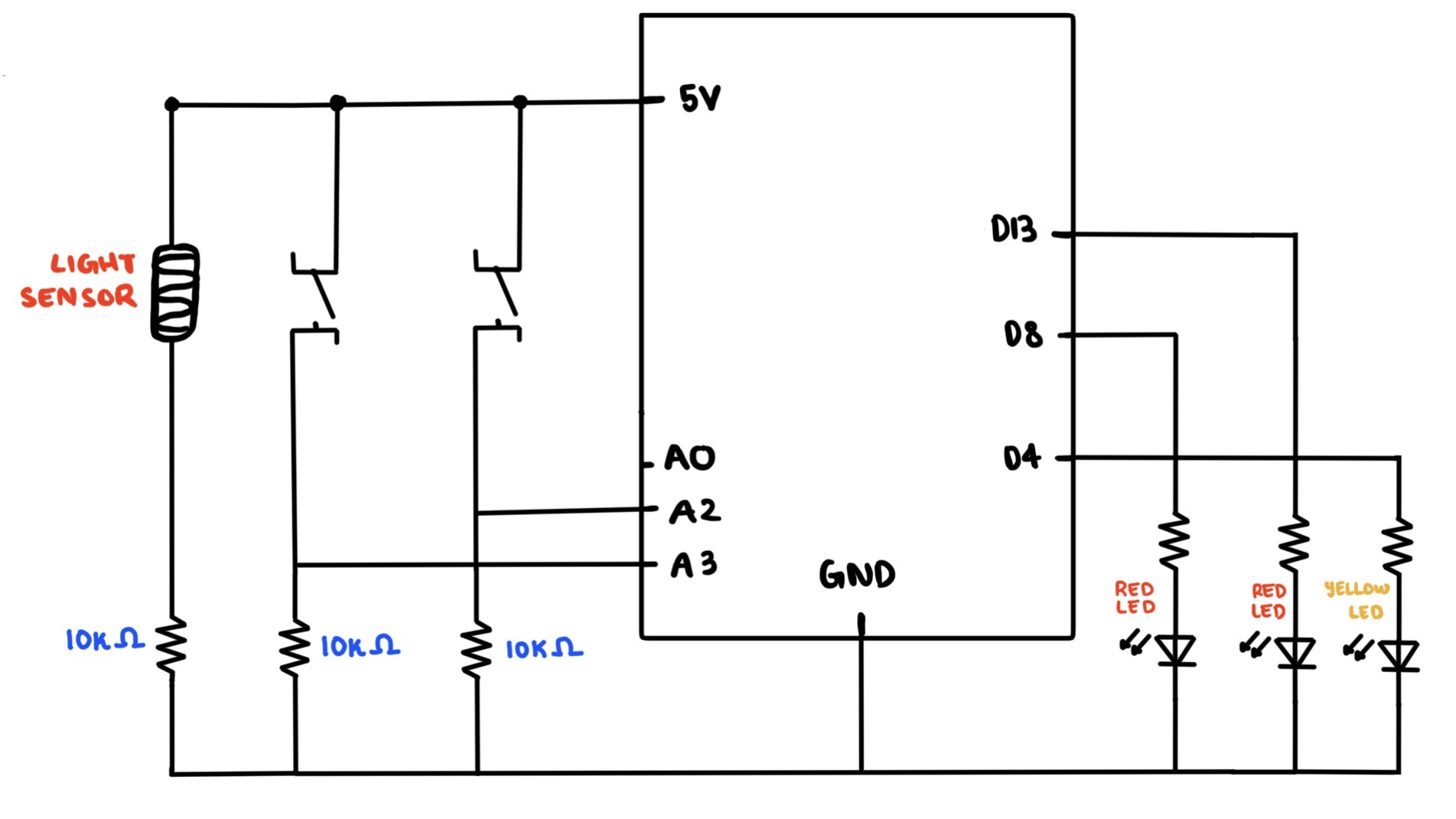
For the light sensor, I would make it such that if the light sensor reads above some specific threshold of voltage, then it would trigger another yellow led to indicate that the light sensor has switched and this would in turn also active both the red led lights to once again alternate while blinking, mimicking that police siren light effect.
Schematic:
Arduino Code:
const int ANALOG_THRESHOLD = 500;   //Constant Threshold of light used for the Light Sensor.


void setup() {
  pinMode(13, OUTPUT);  //Top RED LED
  pinMode(8, OUTPUT);   //Bottom RED LED
  pinMode(4, OUTPUT);   //YELLOW LED
  pinMode(A2, INPUT);   //Switch 1 (Bottom Switch)
  pinMode(A3, INPUT);   //Switch 2 (Top Switch)
  pinMode(A0, INPUT);   //Analog Reader for Light Sensor
}

void loop() {
  int analogValue = analogRead(A0);
  int switch1 = digitalRead(A2);
  int switch2 = digitalRead(A3);

  //If the bottom switch is on, then the bottom light will be on (LED connected to pin-8).
  //Otherwise, it will remain off.
  if(switch1 == HIGH) {
    digitalWrite(8, HIGH);
  } else {
    digitalWrite(8, LOW);
  }

  //If the top switch is on, then the top light will be on (LED connected to pin-13).
  //Otherwise, it will remain off.
  if(switch2 == HIGH) {
    digitalWrite(13, HIGH);
  } else {
    digitalWrite(13, LOW);
  }

  //If both switches are pressed together, then it will call the police_siren() function:
  if(switch1 == HIGH && switch2 == HIGH) {
    police_siren();
  }

  //Above all else, the switches will remain off if neither of the switches are pressed
  else {
    digitalWrite(13, LOW);
    digitalWrite(8, LOW);
  }


  //This is for the light sensor, if the analogValue read from A0 is greater than the threshold value of light.
  //Then it would let the yellow LED turn on and signal to call the police_siren() function.
  if(analogValue > ANALOG_THRESHOLD) {
    digitalWrite(4, HIGH);
    police_siren();
  }

  //If the analogValue read is below the threshold of light, then it will remain off.
  else {
    digitalWrite(4, LOW);
  }
}

//This is the police_siren function which simply takes the two RED LEDS and blinks them alternatively.
//Essentially mimicking a police siren lighting on top of a police car.
void police_siren() {
    digitalWrite(13, LOW);
    digitalWrite(8, HIGH);
    delay(300);
    digitalWrite(13, HIGH);
    digitalWrite(8, LOW);
    delay(300);
}