I switched from my initial plan of making a simple dino jump game to more colourful and fun game called “SHINOBI SPRINT”. The game is a side-scrolling endless runner game based on the famous ninja from the Naruto anime series, as he runs horizontally and avoids obstacles vertically to score points. The game provides a challenging experience where players need to demonstrate agility and reflexes to achieve high scores.
The main objective of the game is to control Naruto and survive as long as possible while avoiding obstacles coming from right towards Naruto. Players need to control Naruto’s vertical movements to avoid obstacles by moving the ultrasonic distance sensor. The plan initially was to move the hand in front of the sensor but after doing some test runs, I realised that the sensor wasn’t picking the values correctly. So, now the player has to carry the sensor in his/her hand and move it away or towards any surface to the control the vertical movement of Naruto.
The Obstacles in the game appear at regular intervals and move towards Naruto and consist of fire images that are randomly placed on the canvas. Players must navigate Naruto vertically to avoid colliding with the obstacles. Colliding with an obstacle ends the game. The game includes a score system that tracks the player’s survival time. The longer the player survives, the higher the score.
Implementation:
The implementation is again simple, player carries the sensor in his/her hand move it up and down on some surface (preferably table) to make Naruto go up or down. The sensor values start from 0 and for the sake of this project the values only range till 460 to make Naruto go up and down within the canvas.
The goal is to navigate Naruto through the gaps between obstacles and avoid collisions. The game ends when Naruto collides with an obstacle, and the player’s score is displayed.
Arduino:
Using serial communication between p5.JS and arduino, I was able to send distance values to p5.js to control Naruto in the game. The Arduino code is responsible for reading sensor data, processing it, and sending it to the p5.js program. Here’s the Arduino Code:
// defines pins numbers
const int trigPin = 9;
const int echoPin = 10;
// const int ledPin = 3;
// int duty = 10;
// defines variables
long duration;
int distance;
void setup() {
  pinMode(trigPin, OUTPUT); // Sets the trigPin as an Output
  // pinMode(ledPin, OUTPUT); // Sets the trigPin as an Output
  pinMode(echoPin, INPUT); // Sets the echoPin as an Input
  Serial.begin(9600); // Starts the serial communication
}
void loop() {
  // Clears the trigPin
  digitalWrite(trigPin, LOW);
  delayMicroseconds(2);
  // Sets the trigPin on HIGH state for 10 micro seconds
  digitalWrite(trigPin, HIGH);
  delayMicroseconds(10);
  digitalWrite(trigPin, LOW);
  // Reads the echoPin, returns the sound wave travel time in microseconds

  duration = pulseIn(echoPin, HIGH);
  // Calculating the distance
  distance = duration * 0.034 / 2;
  // Prints the distance on the Serial Monitor * 0.034 / 2
  // analogWrite(ledPin, duty);
  Serial.println(distance*4);
  delay(150);
}
P5.JS:
The p5.js code handles the game’s main logic and rendering. It includes functions to load images, control the movement of the landscape, manage game states (main screen, gameplay, game over), and handle collisions between objects. The code uses the sprite concept to represent Naruto, obstacles, and other elements in the game. It also includes functions for drawing the main screen and game over screen and the mousePressed function attached to clicking on Play before the start and to restart the game each time it’s over. I’ll be submitting the project below so you can all take a look over the p5.js code.
Communication between Arduino and p5.js
The communication between Arduino and p5.js is established through a serial connection. The p5.js program reads the distance values sent by the Arduino and uses them to control Naruto’s vertical position. The Arduino continuously sends distance data, which is received by the p5.js program. This communication allows the player to control Naruto’s movement in real-time.
Cool Things in the game:
Here are some of game prospects that I am most proud of:
Parallax Landscape: The game features a visually appealing parallax landscape, where the background scrolls at a slower speed than the foreground, creating depth and immersion.
Sprite Animation: The use of sprite animation brings Naruto and other elements to life, enhancing the game’s visual experience.
Intuitive Controls: The game utilizes an Arduino device to control Naruto’s movement, providing a unique and engaging gameplay experience.
Here’s the p5.js code for this project:
Future Improvement
Game Difficulty: Implementing adjustable difficulty levels or introducing new obstacles or power-ups could enhance the game’s replay value.
Audio: Adding sound effects and background music would contribute to the game’s overall atmosphere.
Changing the values received from arduino when communicating data with it: As the sensor values increase from down to up, the movement of Naruto on the screen is opposite the way it should be. I would like to fix this feature in future.
User Testing:
Here’s the video of one of my friends trying to play the game.
I think the controls were not really difficult for the players to understand. My friend was able to figure out the controls on his own and was able to score good score in his 3rd try.
Again, the only problem here is that the movement of Naruto is opposite than the user movement of his/her hands. For example, when going up with the sensor, Naruto goes down. This is one of the main issue I faced and couldn’t find a way to fix it. Hopefully, when I make changes to this project in Future, I’ll be able to figure out the solution for this problem.
For my final project, I created a digital version of the classic Etch-a-Sketch toy which utilizes both Arduino and P5JS. I personalized the design by using neon green and black colors to give it a modern, sleek look. The goal was to replicate the drawing experience of the original toy while adding new features that enhance the user’s creativity and leaving a personal mark on the concept. Additionally, to better reflect my altered version of the toy, I decided to name it Lime Liner.
The Lime Liner was created using an Arduino Uno board and two potentiometers connected to analog pins A0 and A1. The potentiometers control the movement of the cursor on the screen. A switch connected to digital pin 2 was also used to clear the screen. The p5.js sketch is used to draw the cursor and lines on the canvas. The user interacts with the Etch-a-Sketch by turning the potentiometers to move the cursor horizontally and vertically, and pressing the switch to clear the screen. The cursor moves smoothly on the screen and leaves a trail as it moves. The user can create different patterns and shapes by changing the direction and speed of the cursor.
Arduino Code:
The Arduino code initializes the serial communication and reads the values of the potentiometers and switch. It sends the values to the p5.js sketch using the Serial library.
// This code is for an Arduino project that receives data from p5.js and sends sensor data back to p5.js
// The inputs are:
// - A0: first potentiometer
// - A1: second potentiometer
// - 2: switch input

void setup() {
  // Serial communication is started to send the data
  Serial.begin(9600);

  // Set pin 2 as input
  pinMode(2, INPUT);

  // Bidirectional communication starts
  while (Serial.available() <= 0) {
    // Send a starting message to p5.js
    Serial.println("0,0");
  }
}

void loop() {
  // Waits to receive data from p5.js first and then starts executing
  while (Serial.available()) {

    // Parse the incoming data from p5.js
    int left = Serial.parseInt();
    int right = Serial.parseInt();

    // If a new line character is received, read the sensors and button and send the data back to p5.js
    if (Serial.read() == '\n') {
      int sensor = analogRead(A0);
      delay(5);
      int sensor2 = analogRead(A1);
      delay(5);
      int button = digitalRead(2);
      delay(5);

      // Send the sensor and button data to p5.js
      Serial.print(sensor);
      Serial.print(',');
      Serial.print(sensor2);
      Serial.print(',');
      Serial.println(button);
    }
  }
}
P5js Code:
The p5.js code sets up the canvas and draws the cursor and lines using the values received from the Arduino. It also includes functions to clear the screen and prevent the cursor from going outside the canvas.
// Variables for controlling color, position, and switch state
let xPos = 0; // horizontal position of the ellipse
let yPos = 0; // vertical position of the ellipse
let switchState = 0; // state of the switch that clears the Etch A Sketch

// Setup function, runs once when the sketch is loaded
function setup() {
  createCanvas(600, 400);
  textSize(18);
  background(255);
  frame();
}

// Counter variable for the while loop in draw function
let i = 0;

// Draw function, runs continuously to update the sketch
function draw() {
  // While loop to set the button state to 1 only once
  while (i < 1) {
    switchState = 1;
    i++;
  }

  // Map the xPos and yPos to the canvas size to control ellipse position
  fill("#39FF13");
  // Draw the ellipse at a position determined by the mapped xPos and yPos
  ellipse(
    map(xPos, 0, 1023, 70, width - 90),
    map(yPos, 0, 1023, 70, height - 80),
    3
  );

  // Check if the switchState is 1, and call the frame function to clear the sketch
  if (switchState == 1) {
    frame(); // calls the frame function i.e. restarts the sketch
  }
}

// Function to set up the serial connection when spacebar is pressed
function keyPressed() {
  if (key == " ") {
    setUpSerial();
  }
}

// Function to read data from the Arduino
function readSerial(data) {
  ////////////////////////////////////
  //READ FROM ARDUINO HERE
  ////////////////////////////////////

  // Check if there is any data received
  if (data != null) {
    // Split the message
    let fromArduino = split(trim(data), ",");
    // If the message is of the correct length, store the Arduino values
    if (fromArduino.length == 3) {
      xPos = fromArduino[0]; // Update the xPos value based on input from Arduino
      yPos = fromArduino[1]; // Update the yPos value based on input from Arduino
      switchState = fromArduino[2];
    }
    //////////////////////////////////
    //SEND TO ARDUINO HERE (handshake)
    //////////////////////////////////
    let sendToArduino = xPos + "," + yPos + "\n";
    writeSerial(sendToArduino);
  }
}

// Function to draw the frame of the Etch A Sketch
function frame() {
  // Draw the outer frame
  strokeWeight(120);
  noFill();
  stroke("#2BC20E");
  rect(0, 0, width, height);

  // Draw the inner frame
  fill("#010B12");
  strokeWeight(30);
  stroke("#010B12");
  strokeJoin(ROUND);
  rect(70, 70, width-140, height-140);

  // Draw the title
  noStroke();
  fill("#1E1F21");
  textAlign(CENTER);
  textSize(30);
  textFont("Brush Script MT");
  text(" ~ Lime Liner ~ ", width/2, 40);

  // Draw the two knobs at the bottom
  noStroke();
  fill("#010B12");
  ellipse(width-570, 365, 50, 50);
  ellipse(570, 365, 50, 50);
}
Serial communication is used to send and receive data between the Arduino and p5.js. The Arduino sends the position of the potentiometers and button to p5.js, which uses this data to draw on the screen. The clear button also uses serial communication to send a signal from p5.js to the Arduino.
Areas I am proud of and future improvments:
I am particularly proud of the clean and modern design of the Etch-a-Sketch, which makes it stand out from other versions. I also spent a lot of time debugging both the physical and code components of the project to ensure that everything was functioning properly.
Since this was a back-up project, I am a bit disappointed that I did not have the skills and time to finish my initial idea of a radar. Regardless, I feel satisfied with the final version of my project. In the future, one area for improvement would be to add more features to the Lime Liner, such as the ability to change the color of the lines or adjust the thickness of the stylus. Another potential improvement would be to make the stylus wireless to allow for more freedom of movement. Additionally, the code could be optimized to reduce latency and improve performance and a game could be implemented in which the user will interact more with the project.
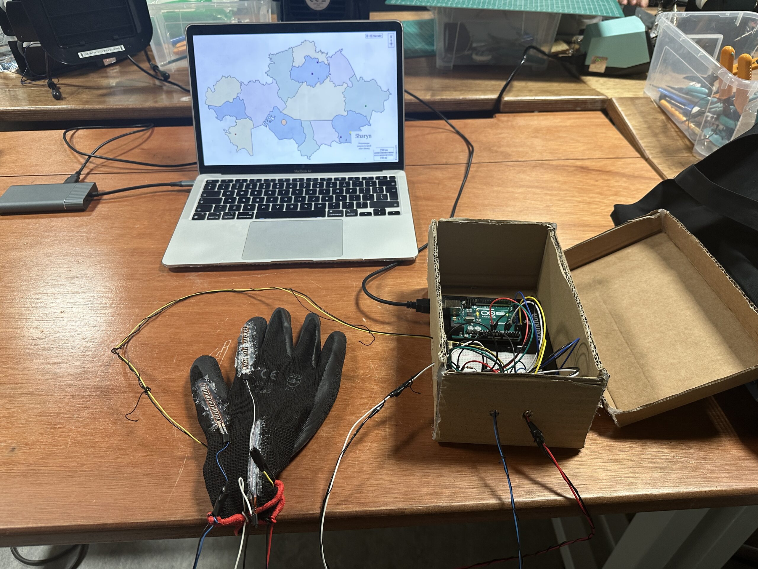
As the name of the project suggests, for my final project I created the “VR” gloves that allows the user to control the hand movement and explore different places of Kazakhstan through their panorama images. I have always been fascinated by the beauty of my country, and I want other people to see those beautiful places as well. The destination points that the user can explore include a variety of landscapes, starting from dense forests and mountain lakes, and ending with deserts and canyons.
The reason I named this project “VR HandVenture” is because moving inside the panorama image closely resembles the movement inside a VR world and our right hand is the main instrument through which we can explore the place ( “HandVenture” comes from the word “Adventure”; shoutout to Saamia and Sanjana who helped me come up with this project name that I think perfectly encapsulates the project’s main idea).
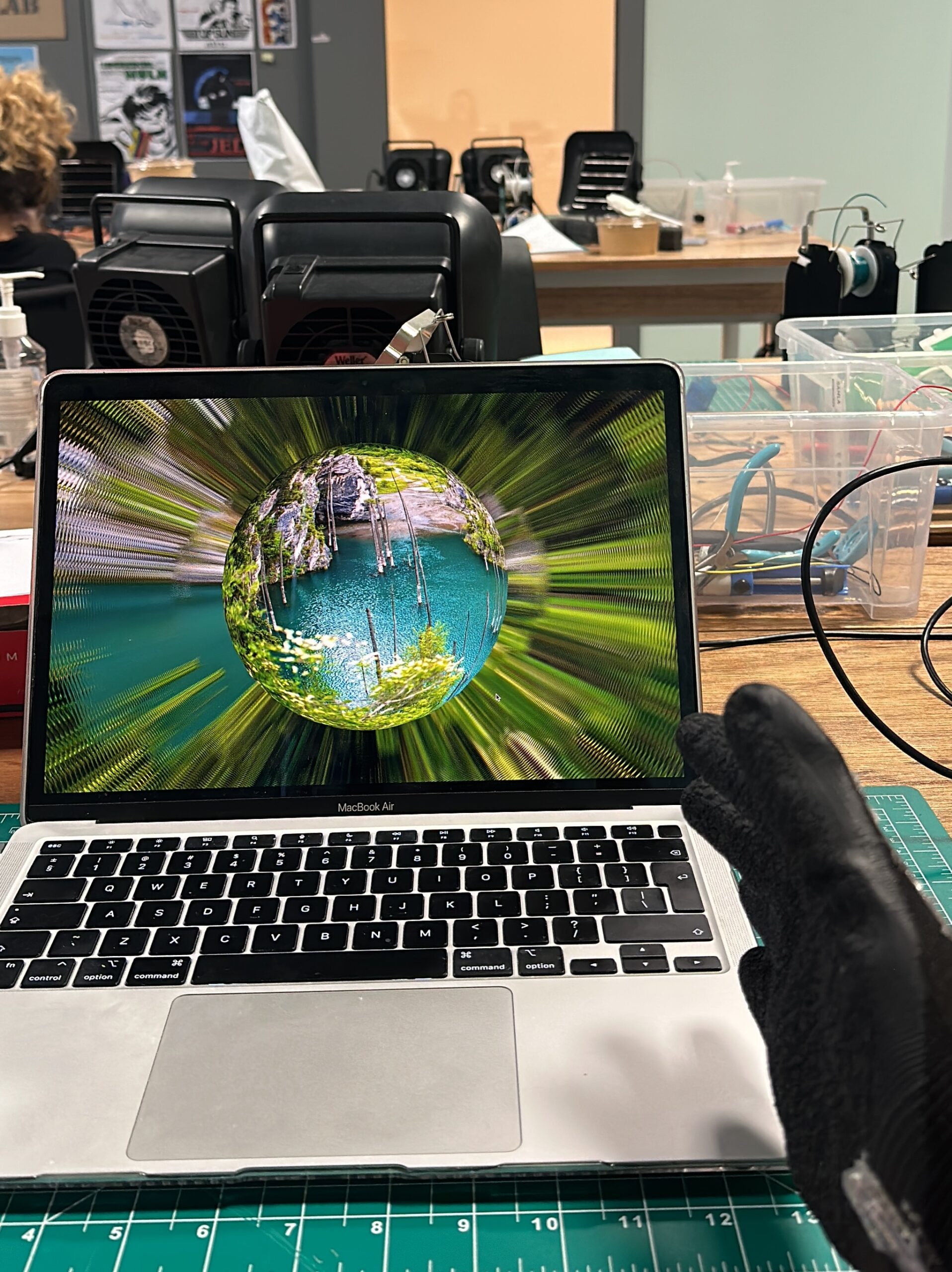
After the welcome page and following the instructions page, the user will be prompted to enter the main page, a page displaying Kazakhstan’s map, where he/she later can choose the destination he/she wants to visit. Before clicking on the corresponding destination, a small information about the place, including the name of the place and a short description, will be displayed to the user. The user can explore each destination through moving inside panorama image using the hand movements. The movements that are available to the user are moving left, right and zooming in, out. When the user bends his/her hand to the right the image will move right, when bends to the left the image will move left, and bending index finger will allow the user to zoom in, while bending the thumb will allow to zoom out. When zooming out of the image, after reaching a certain threshold, the user exits the image and reaches a 3d space where the image will now be displayed in form of a sphere.
Implementation:
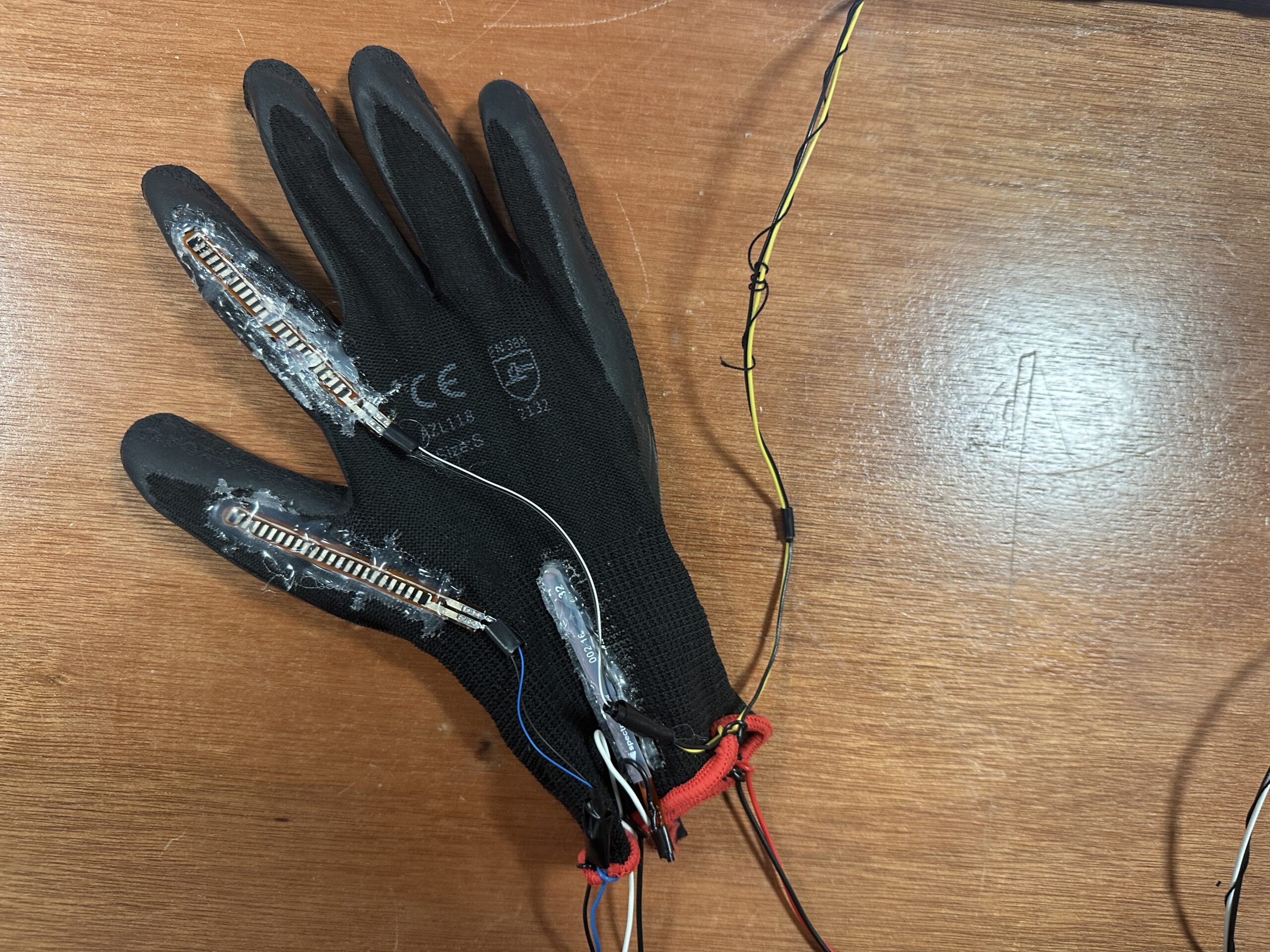
I attached flex sensors to the glove and used analog input received from them to detect the user’s hand movement. I attached two flex sensors to both sides the glove which are used to sense when the user bends his/her hand right or left and move the panorama image accordingly. I also attached two sensors to the index finger and to the thumb which are used to zoom in and zoom out inside the image. I’ve used pretty useful feedback from the user-testing so I set the limit to how much the user an zoom in and out, as this has been creating problems with the experience because the sensors are too sensitive for detecting when the user continuously bended his/her hand.
Arduino code:
Arduino is used to read analog input from the flex sensors which it then sends to p5.js through serial communication.
const int flexPin1 = A1; //controls movement right
const int flexPin0 = A0;  //controls movement left

const int flexPin5 = A5; //controls zooming in
const int flexPin4 = A4; //controls zooming out

int value_left; //save analog value
int value_right;
int value_zoomIn;
int value_zoomOut;

void setup(){

  Serial.begin(9600);

  //start the handshake
  while (Serial.available() <= 0) {
    Serial.println("0,0,0,0"); // send a starting message
    delay(300);
    delay(50);
  }
}

void loop(){

  // wait for data from p5 before doing something
  while (Serial.available()) {
    int isMoving = Serial.parseInt();
    if (Serial.read() == '\n') {

      //read the inputs from flex sensors
      value_right = analogRead(flexPin1);
      value_left = analogRead(flexPin0);

      value_zoomIn = analogRead(flexPin5);
      value_zoomOut = analogRead(flexPin4);
      delay(5);

      //send them to p5.js
      Serial.print(value_right);
      Serial.print(',');
      Serial.print(value_left);
      Serial.print(',');
      Serial.print(value_zoomIn);
      Serial.print(',');
      Serial.println(value_zoomOut);
   }
  }

}
p5.js code:
p5.js code is too large, so I’m embedding the link to my code.
p5.js is handling the main functions of the code such as creating visuals and a panorama-like experience, moving the image according to the value received from the Arduino, creating user interactivity with the map, popping text boxes when the user hovers over the destination rectangles, etc.
Communication between Arduino and p5.js:
Arduino gets the analog input from the flex sensors and sends them to p5.js, which measures that value, and if it exceeds a certain threshold, it moves the panorama image accordingly.
Demo:
Aspects that I’m proud of:
I’m really proud with how everything in this project turned out. I wasn’t really expecting initially that this will resemble a VR experience, so this was a pleasant surprise for me that I discovered during the process of making. I’m also proud with the idea of using gloves to move inside the image as I think that is a pretty cool and novel idea. In terms of the hardware part, I’m glad with how sensors are working as they’re giving pretty accurate answers since they have been placed on right locations on the glove.
Areas for future improvement:
One of the areas for future improvements include adding more destination points to the map, because I have only 6 places so far. Also, I used hot glue to attach the flex sensors to the glove. Even though the connection is good, it may not be long-term so one of the improvements could be sewing the flex senosors to the glove, as it is made of sewable material. In addition to that, it’s highly recommended for the user to hold the hand in a certain position initially (palm facing left side of the body and fingers pointing outwards) so that sensors would work best, and I’m planning on explaining it to user by demonstrating the hand position. One of the better ways to do this for the future would be recording a demo and attaching a video to the instructions page or adding a picture/gif with the corresponding hand posture.t
For my final project, I created an interactive tool that helps to visualize stress levels during finals seasons. It allows college students to relieve stress through squeezing and screaming and produce a unique visual mapping of their stress. The tool incorporates a microphone and a stress ball on a board. The pressure and sound input are used to determine stress levels based on duration and intensity, and the results are displayed on the screen as moving color dots. The more stressed you are, the bigger and redder your circles are and the faster they move.
Implementation:
The interaction is straightforward – the nature of a stress ball makes it obvious that one needs to squeeze it and to guide the users to use the microphone, I put a little “Talk to me :)” label on top of it. The users interact with the project by either squeezing the stress ball or screaming (or talking, but preferably screaming) into the microphone.
The arduino part of the code is very straightforward as well – arduino simply takes the input values, averages over 10 consecutive values to smooth out the readings, and sends the values to P5JS.
Without interaction with Arduino, the P5JS code creates circles on the screen with randomized but bounded positions and radii and makes them move up the screen again, with randomized but bounded speed. The circles out of the frame are removed and every 100 frames there is a new circle generated.
P5JS takes the input values and maps them onto 3 variables: the radius, color, and speed of all the circles present on the screen. The color and size of the circles are dependent on the force sensor’s readings. When the stress ball is squeezed, the dots get enlarged and change their color to red.
The code for displaying a single circle is as follows:
display() {
    let radius = map(fVal, 0, 1023, 0, this.size);
    let colorR = map(fVal, 0, 1023, 0, 255);
    let colorB = map(fVal, 0, 1023, 255, 0);
    let colorG = 0;
    for (let i = 0; i <= radius; i=i+2) {
      noStroke();
      fill(color(colorR, colorG, colorB, 2));
      ellipse(this.x, this.y, i, i*this.f);
      }
  }
The speed of the color circles depends on the value of the microphone. I found the base rate of a room is under 600 on the microphone reading, so I set the detection threshold to 600. To control the randomized but bounded speed of the circles, I added a variable speedFactor that I use when changing the speed.
//Defining global variables related to speed
let minSpeed = 1;
let maxSpeed = 5;
let speedFactor = 1;

//randomizing the speed for each circle
let s = random(minSpeed, maxSpeed)/4;

//update function in the Circle class that updates based on the speedfactor
update() {
this.y -= this.speed*speedFactor;
}

//changing the speedfactor according to the microphone reading (and by using speedfactor changing all of the randomized speeds by a constant scale)
if(micVal>600){
    speedFactor = micVal/600;
}else{
    speedFactor = 1;
}
//NOTE these are snippets from different parts of the code
Challenges
I had 2 big challenges in this project. First, it was connecting the hardware as it was my first time soldering or building a shell for my circuit. I ended up messing up some sensors and wires, and in the end not using them but sticking to a very simplistic design of my sensors on abox.
Another big challenge was making the gradient circle in P5JS that fades toward the edges. I tried 4-5 different methods, including drawing just the outline of a circle, using the HSB color mode, lerp function, and the one that I stuck with – drawing a lot of circles of the same color and very small alpha value so that the layering of many circles creates the saturated color in the middle. I am still not fully satisfied with this method though as when there are more than 15 circles on the screen, it gets very laggy and there are way too many objects on the screen (from a computational perspective, not a visual). I would love to find a better, more efficient way to do this without having to draw 4000 (number of circle groups, 10 in my case)*(maxRadius, 400 in my case) circles in each frame.
However, I am still proud of my final project and really like the idea of using squeezable objects (like the stress ball I used) to be part of computer controlling (I also created a very small version of a flappy bird game that uses the squeezer as a controller, which is simplistic but really fun).
User Testing
Without instructions, users were able to figure out that they are supposed to squeeze the stress ball and speak into the mic. The connection between the stress ball and the color circles on the screen was pretty obvious, but the positioning of the microphone made it a little awkward to both watch and interact with the tool, which could be an area for improvement.
Sanjana was my user-tester for the latest version of my final project. As per the instructions, I didn’t give her any instructions before she started testing it, and was able to receive some valuable feedback on the ways I could improve instructions given to the user and discovered one bug that has a potential to be a cool feature haha.
Video:
Feedback:
Sanjana found it pretty easy to navigate the user interface and how the mapping between the glove and p5.js work. I feel like I needed to explain her that sensors are very sensitive so sometimes even minor bends affect the movement. The parts of the project that are working well are communication between the flex sensors and p5.js and also the graphics.
Through the user-testing, I realized that I should make it clearer in the instructions page how the user should hold her hand so that sensors would work the best way. I should also mention that the right, left, zoom in and out movements sometimes can be combined when corresponding hand movements are combined (i.e. when the user bends her thumb while bending her hand right)
This user-testing also helped me realize that that when zooming in or out, there’s some limit till which u can zoom in/out so that the image will not get distorted. By zooming in too much you can get very deep into the image so that only pixels will be visible and the image presented will not make sense. However, by zooming out of the image you can reach a cool 3d space where the image will cover the sphere (the cool feature I was talking about). See below image for reference.
I started this project with the purpose of encapturing the essence of this semester, a type of memorabilia. In order to figure out how to do that, I have to go through many types of interaction and setting to land on a viable idea that would require a more simplistic interaction with a scope for storytelling. Finally I decided to use a circular structure which a person can complete 1 by 1 each segment. The purpose would be to finish the whole circle (journey). As I have started to conceptualized the activity to be like a journey, I felt that the literary framework of “Hero’s Journey” would be a great fit. In order to reflect the “Hero’s Journey,” I divided the framework onto 5 segments accordingly: acquiring knowledge/advice, enjoying lively goods, getting distracted from work, working hard to reach goals, and reflection/atonement. Hence, each segment carries these themes respectively from 1 to 5. I included activities and artists that make frequent visits to my day to day life, as by doing this I was able to commentary on our daily lifestyles of growth and change, our hero’s journeys. Something interesting I added is the option of staying on a tile and experiencing it or just skipping by stepping on the next tile. In some cases, skipping a tile is show of no effort, and in others it is a show of determination. Finally, the final page upon completing the tile 5 explains the metaphor on hero’s journey as each of ours journey, and reminds that we are all going through our own journeys next to each other or even together.
Implementation
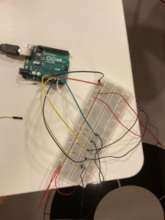
There is a circuit implementation as well as the software implementation.
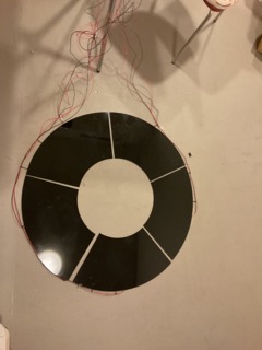
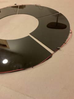
For the circuitry, I have had to do some soldering. For the setup of the circle, I have designed a circle with an inner radius of 20 cm and outer radius of 45 cm. The circle is divided into 5 segments which are laser cut to acrylic plates. Under each segment there is an FSR (force sensing resistor), which all are parallel to each other and are in series with 10k Ohm resistor. The values are read analog.
In terms of software, I have had to commit day and nights as there were to many areas to cover which I quickly realized was too much for my plate. For each tile I have utilized different approach. The first tile encompasses a simple representation of knowledge by an image of a quote on an old paper in a library. The second tile has a song playing on a Spotify interface with respective lyrics that touches upon life, youth and joy. The third tile uses the screen recording that I have taken of my own reels feed in instagram. I wanted to incorporate ‘scrolling’ as it is one of the biggest escape/distarction methods I use in my daily life, and as I have recently lost my phone I have been especially realizing how refreshing it is to not have these distractions. In the third tile there is a video that pops up that mentions you have to jump to reach stars which is shadowing. The user has to make the choice of continuing to the next tile themselves, as this is a conscious decision I made. If there is no decision to leave, you are stuck in the loop of social media forever. In the fourth tile, there is a starry night, with a girl sitting on a moon. When the use jumps on the tile the star gets closer and closer to the girl. When the girl reaches the star or user just moves onto the next tile without trying to reach the star, the 5th tile starts. In the 5th tile, there is cycles by Mac Miller playing, with a relaxing image of a midnight beach. This room is designed to be contemplative where the user should just reflect and absorb. When the sequence finishes the final page is prompted. The final page clarifies the concept of the “hero’s journey” and talks about the overarching theme of each tile, and makes a note on how we are all on our own journeys in the company of each other.
The start page. The icon lights up when the mouse is hovered above.
In the implementation side, I had to experiment with different fonts, images, video representation, concept markers and general design. Managing sound and video was especially challenging.
The user only has to take steps as they seem to fit. Similarly they should jump on the 4th tile if that’s something they wish for. They will be having headphones on as well as a tablet in their hands which they can receive all the inputs.
My Arduino code is very simple which 5 analog readings are received and passed together at each loop to the serial connection p5.js as follows:
void setup() {
  Serial.begin(9600);
}

void loop() {
  //receives information from the analog pins accordingly and assigns them
      int tile1 = analogRead(A0);
      int tile2 = analogRead(A1);
      int tile3 = analogRead(A2);
      int tile4 = analogRead(A3);
      int tile5 = analogRead(A4);
  //passes the readings seperated by comma from the pins directly to p5js
      Serial.print(tile1);
      Serial.print(',');
      Serial.print(tile2);
      Serial.print(',');
      Serial.print(tile3);
      Serial.print(',');
      Serial.print(tile4);
      Serial.print(',');
      Serial.println(tile5);
  //marks the end of 1 run of data by continuing to a new line
}
p5.js Code
In p5.js code is quite long for this code and therefore please follow the following link to reach the editor that hosts my p5.js code.
I have described the general progress of the experience in terms of p5js in the previous section. One thing interesting about my code is that since creating canvas and creating a video element at the same time is not allowed, instead I displayed the videos by passing them as images and displaying them quite fast. This allowed me to switch videos and come back to any, play around with displays, and music. There is also more freedom in terms of the placement of the video displayed. Basically, the video becomes that is comparatively way easier to manipulate in p5js. However, there needs to be considerations for the frame rate of the sketch. The following is tile 3 code, one of the parts in which I implemented this method:
let organizerCount = 0;

let changeVideo = 0;
let duration = 0;

//the main setter for the videos has to be called once
function organizer() {
  short.size(350, 1.78 * 350);
  short.loop();
  short.hide();
  reel.size(350, 1.78 * 350);
  reel.loop();
  reel.hide();
}

//function checks whether there is pressure on the next tile
//to prompt up the next tile event
function tile3Function() {
  if(dataTile4 > 100){
    //the videos are stopped and the selector value is changed
    reel.stop();
    short.stop();
    selector = 4;
  }

  if (!organizerCount) {
    //the organizer function is called only once
    organizer();
    //escape from if condition
    organizerCount++;
  }
  //setup the main reel video with the 'jump for stars' video
  //popping up randomly
  else {
    background(255);
    frameRate(60);
    //put out video image by image in order to have a canvas to
    //manipulate
    let img = short.get();
    let mg = reel.get();
    //formatting
    strokeWeight(0);
    stroke(0);
    fill(0);
    //the bacground of the phone is black
    rect((width - img.width) / 2, 20, 350, 1.95 * 350);
    //randomly prompt up the 'jump for stars' part
    if (changeVideo == 2) {
      //stop the main reel video
      short.pause();
      image(mg, (width - mg.width) / 2, (height - mg.height) / 2);
      changeVideo = 2;
      duration++;
      //run the jump for the stars video for a set time
      if (duration == 60) {
        changeVideo = 0;
        //switch back to the main reel
        short.play();
        duration = 0;
      }
    }
    //the random value generaor prompt the 'jump for stars' video
    //and runner for the main reel video
    else {
      changeVideo = int(random(1, 900));
      image(img, (width - img.width) / 2, (height - img.height) / 2);
    }
    //phone image on the videos that are played
    phone.resize(img.width * 2.55, img.height * 1.35);
    image(phone, width/10.2, -80);
  }
}
Communication between Arduino and p5.js
I have used the exemplary communication that was given to us in the class. Hence, there is the following snippet in my p5js sketch to receive serial data from Arduino, as well as the needed library and html edit for this communication. Reading for the p5js from Arduino checksfor 5 data points and stores them into 5 variables to be used in other parts of the code.
function readSerial(data) {

  if (data != null) {
    // when there is an actual message, receive and split the message
    let fromArduino = split(trim(data), ",");
    // if the right length, then proceed and assign one by one to variables
    if (fromArduino.length == 5) {

      dataTile1 = fromArduino[0];
      dataTile2 = fromArduino[1];
      dataTile3 = fromArduino[2];
      dataTile4 = fromArduino[3];
      dataTile5 = fromArduino[4];
      print(
        dataTile1 +
          " " +
          dataTile2 +
          " " +
          dataTile3 +
          " " +
          dataTile4 +
          " " +
          dataTile5 +
          "\n"
      );
    }
}
There is also another function that prompts up when space bar is pressed to establish the serial communication between Arduino and the p5js editor.
function keyPressed() {
  if (keyCode == 32) {
    // important to have in order to start the serial connection!!
    setUpSerial();
  }
}
Challenges
The whole project was quite stressful for me as I felt early on that there were some loopholes in the logic and storytelling aspect of it. Despite figuring out the physical interaction of it to be simple and clean, I realized that even after giving days to plan out the storytelling did not change how complicated it turned out to be in the end. I was trying to sketch out each tile and transitions between tiles as well as the general storytelling framework I was going to use for so long, that I experienced a little withdrawal in my capability figure this out. So I just simply sat down and drafted what I had on my mind till now.
In terms of Arduino, the most challenging part was to figure out how to evaluate data to detect jumping, as 1 jump would give consecutive no pressure values to p5js, which disrupted the work on my tile 4. Hence, I decided to counter this by setting the frame rate a set value, so that irrespective of the speed that Ardino delivers to the computer the receiver of the data would be ordered and easy to analyze and deal with. After doing that, I was able to see trends in how the force reading changes during a jump and make the necessary adjustments to register jumps one by one.
The p5js section is definitely more complicated part of my code, and without doubt at every tile (out of 5) there was a long design process as I tried out styles. I incorporated videos and sounds heavily as my experience with this semester was completely defined by videos and sounds as well. In doing that, for example, in the distraction (scrolling in Social Media) video I had to find a way to have the video on but also a canvas so that I can have a phone silhouette on as well as switch between 2 video entities randomly. Figuring out this part was very challenging and had to do a lot of research in terms of how to run videos in p5js. I had a similar struggle in controlling sound files as well, which required a similar amount of commitment in its logic.
While doing the p5js, the rest of the methods I used were not completely new but still challenging. An issue I have had problems till now is the completeness and digestibility of the total experience. Despite putting more time into the design and storytelling sketch this time, I felt that there was still aspects that just did not feel complete. For example, I spent such a long time on tile 2 (which a song is listened in the topic of jot of living), I changed the construction of the page at least 10 times, because I was not able to figure out what kind of delivery worked best out of each option in the grand scheme of the project. Looking at the user reactions, I think the project needs a pamphlet prior to being used, that will allow the users to get into the mindset of the project.
Successes
The experience finally running from the start to finish was what I felt the most proud about, as I have been working on it piece by piece for so long. I’m especially the most proud about the simple experiences like in the last tile just watching the night sea roll to sound of Circles playing. Similarly, reaching the stars tile is so simple yet feels so important and beautiful to me. I was happy to be able to put a concept that I felt to be true and constantly felt around me into a project. I always felt that we were all so consumed with our struggles, successes, distractions, reflections all the time, which always circled back to start. Slump would appear every other week. We would overwork ourselves for a couple weeks every now and then. We would become especially introspective every now and then. I just wanted to concretely draw this process out, personalized with the tokens that I believed marked this journey. My main goal all along the project was to have the scene after tile 5, where many circles appear, intersecting each other. This is what I felt thankful for the most throughout the whole semester. We all had to go through our journeys but it felt even more worthy because we got to have each other’s company: intersecting circles/journeys with our intersecting lives.
Future Improvement
For future improvement, I would want to make this project even more immersive. I feel that every moment of it works to establish a feeling or understanding in the user, which requires the full attention of the user. Hence, I was thinking a fully immersive experience that would limit the user’s ability to look away would definitely align with my project. This would also help to emphasize that our power is on how we respond to what comes our way. We get to look away (step away), but we don’t get to just not see. I think that in terms of this project, this was the overarching dynamic that was created and there are many ways this could be implemented by changing the experience’s location from computer screen, to projected screen on 4 walls inside a small chamber created with projection fabric.
User Testing
User testing was done but I cannot paste the specific video/photos due to privacy reasons. However admittedly there was haste in terms of rushing through the steps similar to my previous project in midterm. It seems that I will have to think more about how to handle this issue by changing the interface or giving a booklet of directions to read before users try out the the journey.
Additional User Testing:
User Input Highlights:
The user did not mention hardships in terms of the instructions of the experience.
There were interesting insights and take about the individual perception of the journey.
The linked circle outro was especially a favorite, as according to the user it emphasized how people come by to our lives and even if they have to leave, there is a possibility they will be back as there are two points of intersection between each circles.
The user made interesting comments about the distraction tile, and how it was constant battle between looking at the reels and looking at the “reach the star” reel.
The user mentioned that it did not feel as if it was a circle but was more of a path as they were not the same person at the end of the journey. After talking about my inspirations of hero’s journey concept and how I made parallels between the literary device and the experience, they found it very intriguing. They think that the other users should be redirected to receive more information on hero’s journey upon going through the project as well.
The user felt that instructions were generally clear. They did not know what to do after being trapped in the reflection room, but as this was my intention as a part of the project I though it was exactly how it should be when I saw the user just switching between tiles to try to get out of reflection room. The user thought it was a good example of the things we could not run away from/just leave.
In order to gather feedback on the usability of my project, I conducted a user interaction test by having people try the project without any prompts or instructions. The purpose of this test was to evaluate how intuitive the design was and how well users were able to understand the mapping between the controls and the resulting experience.
Overall, the results of the test were mixed. Some users were able to figure out the controls quickly and enjoyed the experience, while others struggled to understand how the controls worked and what their effect on the project was. A common area of confusion was the use of the two potentiometers, as some users were unsure of which one controlled the horizontal and vertical movement of the line.
Despite the challenges some users faced, there were several areas of the project that worked well. Many users enjoyed the retro feel of the etch-a-sketch and appreciated the unique green and black design. The feedback on the physical controls was also positive, as users found them easy to use and responsive.
Based on the results of the user interaction test, there are several areas that could be improved in the project. One approach could be to provide more detailed instructions or visual aids to help users understand the controls and how they affect the project. Another potential improvement could be to add a feature that allows users to save and share their creations, adding a new level of engagement and creativity to the project. Also, the knobs of the potentiometers should be made bigger so the users can control them more easily.
For now, my plan is to build a car which will be controlled using hand gestures from the user. To do this, the control system will track the user’s hand position, interpret the hand gestures made by the user and translated the hand gestures into commands that’d be used in moving the car. To add up to the obstacle detection features of the car, i will use the ultrasonic sensor. The ultrasonic sensor would detect the distance between the car and obstacles and i will have the minimum distance set at a value so the car automatically undergoes rerouting.
IMPLEMENTATION
My goal is to develop a control system for a car by integrating the P5JS tracking system. This system will enable the car to be controlled through hand gestures made by the user. To achieve this, I will utilize the advanced capabilities of PoseNet for detecting the user’s hand position accurately. By interpreting the hand gestures made by the user, the system will translate them into commands that can be used to move the car.
The P5JS tracking system will be responsible for monitoring and analyzing the forward and backward movements of the user’s hand to control the car accordingly. It will allow the user to steer the car in the desired direction by moving their hand forward, backward, left or right. The tracking system will accurately detect the user’s hand position and interpret the hand gestures in real-time, enabling seamless and responsive control of the car.
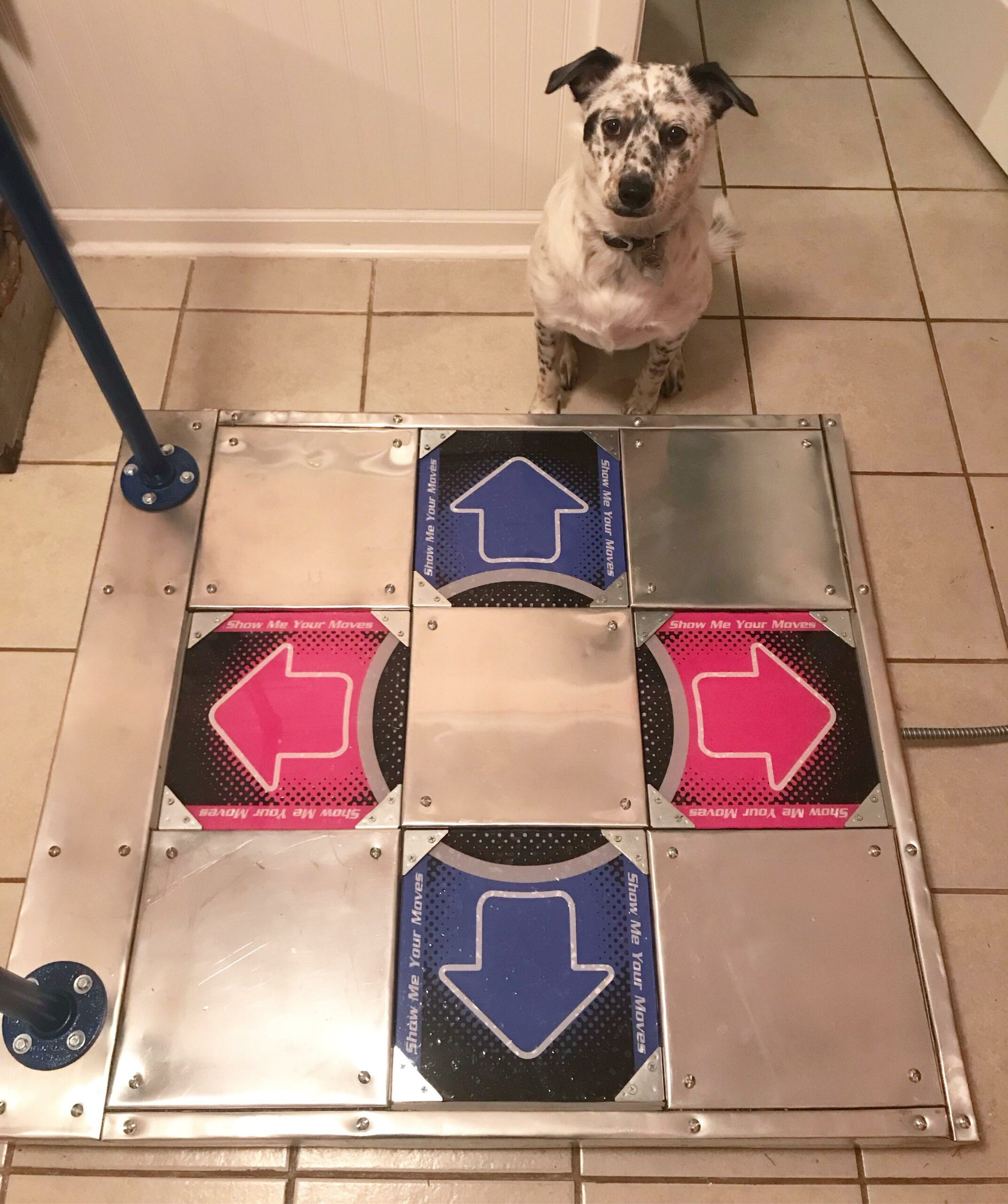
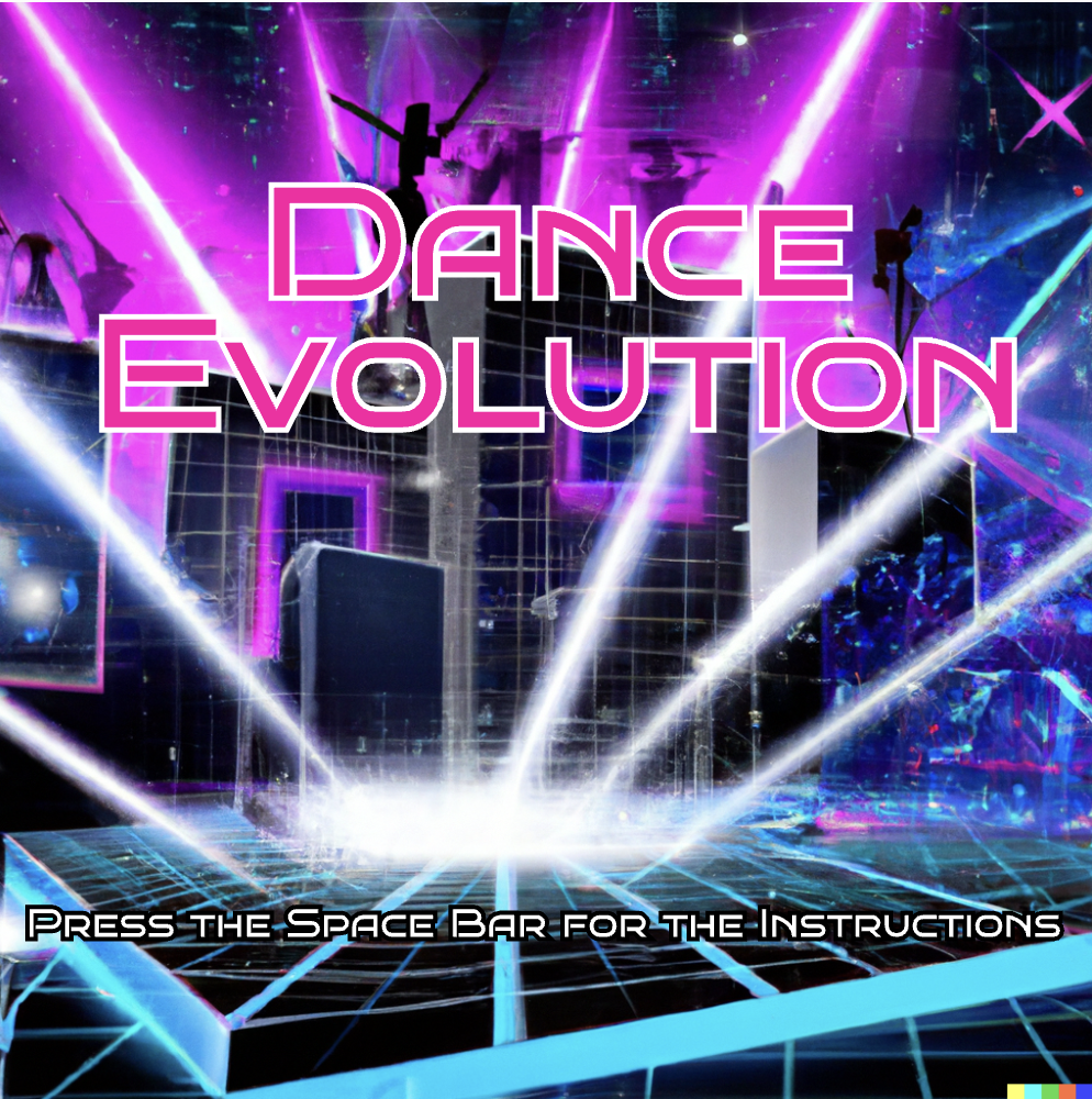
For my finally project, I was inspired by a classic Japanese video game called “Dance Revolution.” In this game, the user hears a song and has to tap on the right tiles of the platform that is under them in order to win the game: the tiles on which the person has to tap on appear faster and the game becomes harder over time. However, to put my own spin on the project, I decided to reverse the idea, and create “Dance Evolution.” In this game, the user will not be given a prior song but rather a set of tiles that they have to press on, similar to the original, and construct the song themselves.
picture taken from https://www.reddit.com/r/DanceDanceRevolution/comments/85guhf/my_self_made_ddr_pad_gallery_and_howto_in_comments/
The tiles will be modeled after the iconic “Dance Revolution” tiles.
Implementation:
The user will construct the song with the help of a set of successive arrows that they have to tap on, which in turn represent a certain instrument. After tapping, these instruments will be layered and will start turning into an actual song. The trick is that the user has to tap on the arrows/tiles in a timely manner, as the time slot for a successful tap will shrink over time. The user wins if they are able to tap on all tiles correctly and create the song that consists of all instruments: the beat, the bass, the chords, the melody, the pad, etc. The user loses if they do not tap on the tile on time, thereby ruining the structure of the song.
The instruments will most likely be generated using p5.js, in order to add an element of randomness and unpredictability so that the melodies and the beats heard in one round of the game will be different in another round. The user will also have the possibility of changing the key of the song by using a distance sensor, allowing them to hear the song in different renditions of their own volition.
Arduino input:
There would be nine tiles in total and five of them would have a function. Each tile would be connected to a pressure sensor that would then trigger some sort of operation. The tiles on the sides pointing up, down, right, and left would be used for the game itself, while the tile in the middle would perform general functions such as restarting the game, going from one window to another.
Meanwhile, p5js would light up the tiles due to an LED connected to the tiles showing the user what tile to press on.
As someone who is interested in physical computing, I have been inspired by previous DIY radar projects that use ultrasonic sensors and servo motors to detect objects in real-time. However, to make my project more original and challenging, I will use P5.js, a JavaScript library for creative coding, instead of Processing, which is commonly used in similar projects. By incorporating P5.js, I hope to create a unique and interactive radar system that combines hardware and software components. The concept of the project is to build a radar system that can detect objects and display their location and distance in real-time. The system will consist of an ultrasonic sensor, a servo motor, an Arduino board, and a computer running a P5.js program.
Technical aspect
For the Arduino program, I plan to use the ultrasonic sensor to detect the distance of objects in front of it. I will then use a servo motor to rotate the sensor and sweep it across a 180-degree arc. At each angle, the program will read the distance measurement and send this data to the P5.js program over the serial port. Additionally, I plan to control an LED to indicate the presence of an object within a certain distance threshold.
The P5.js program will receive the data from the Arduino program and use it to display the location of the detected object on a radar screen. Using polar coordinates, the program will map the distance and angle of each object and display them as a dot on the radar screen. The program will also include a graphical user interface (GUI) that allows me to adjust the distance threshold and other parameters.
To communicate between the Arduino and P5.js programs, I will send data over the serial port. The Arduino program will send the angle and distance of each detected object, as well as the state of the LED. The P5.js program will use this data to update the radar screen and the GUI.

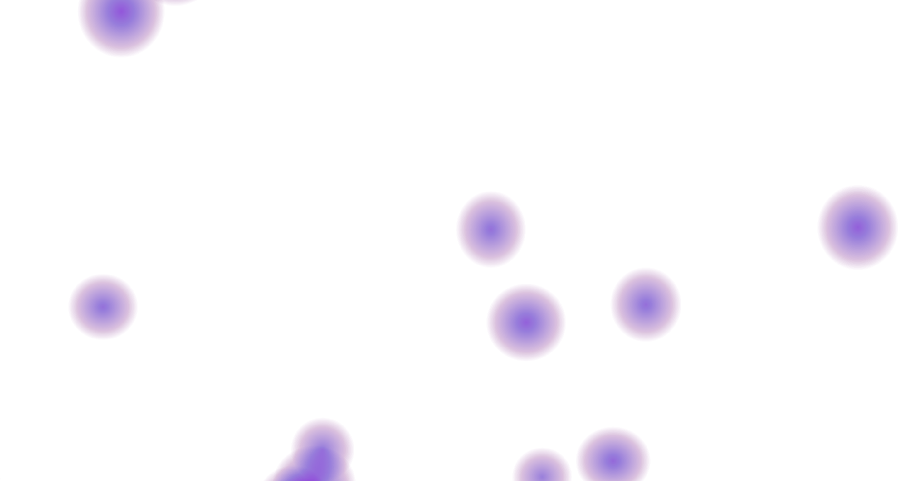 Color circles when the user is not squeezing the stress ball
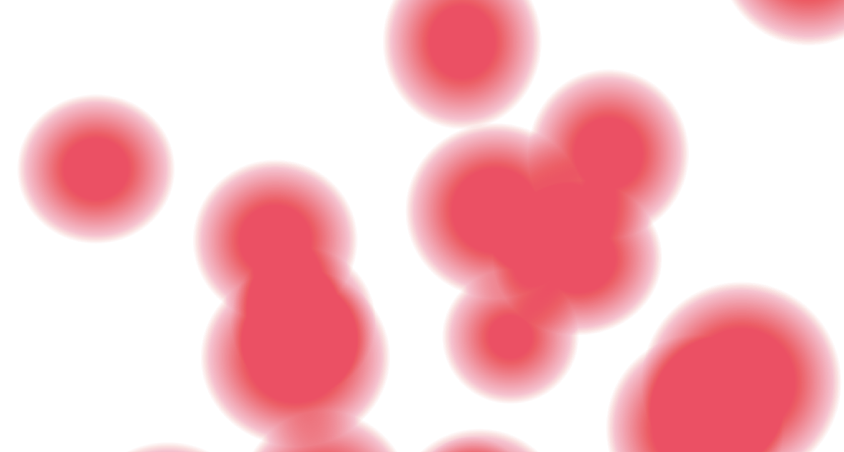 Color circles when the user squeezes the ball