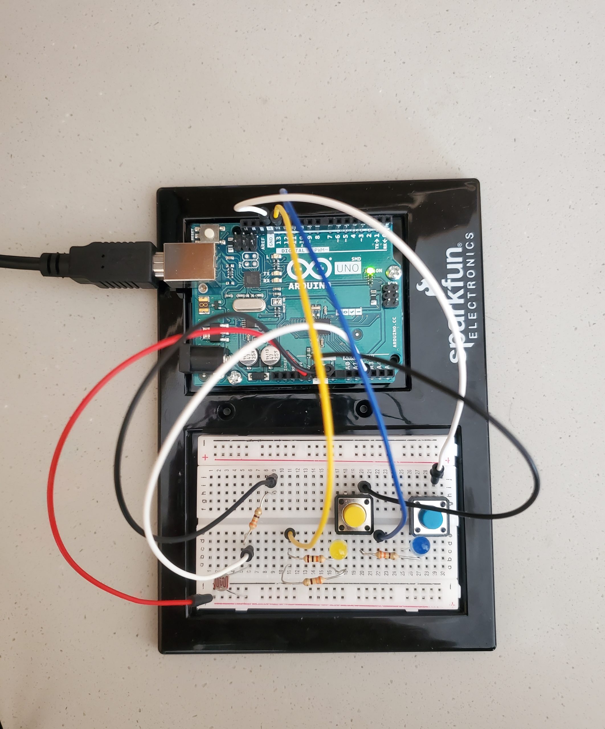
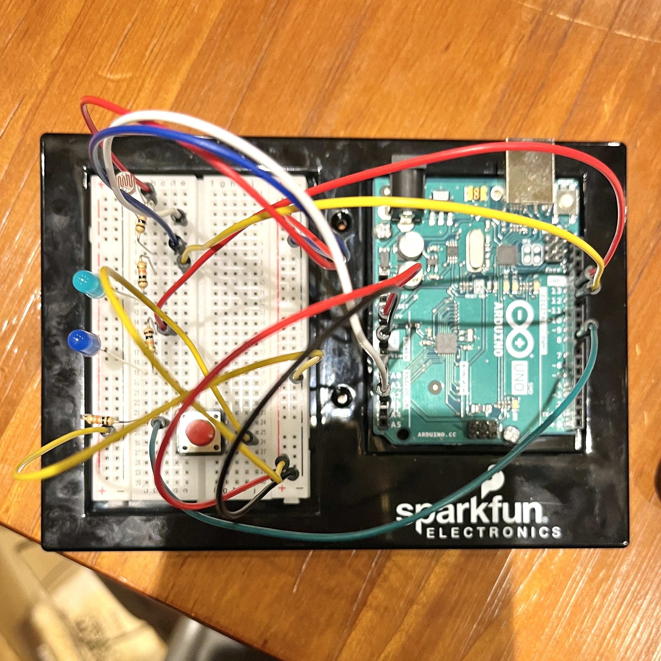
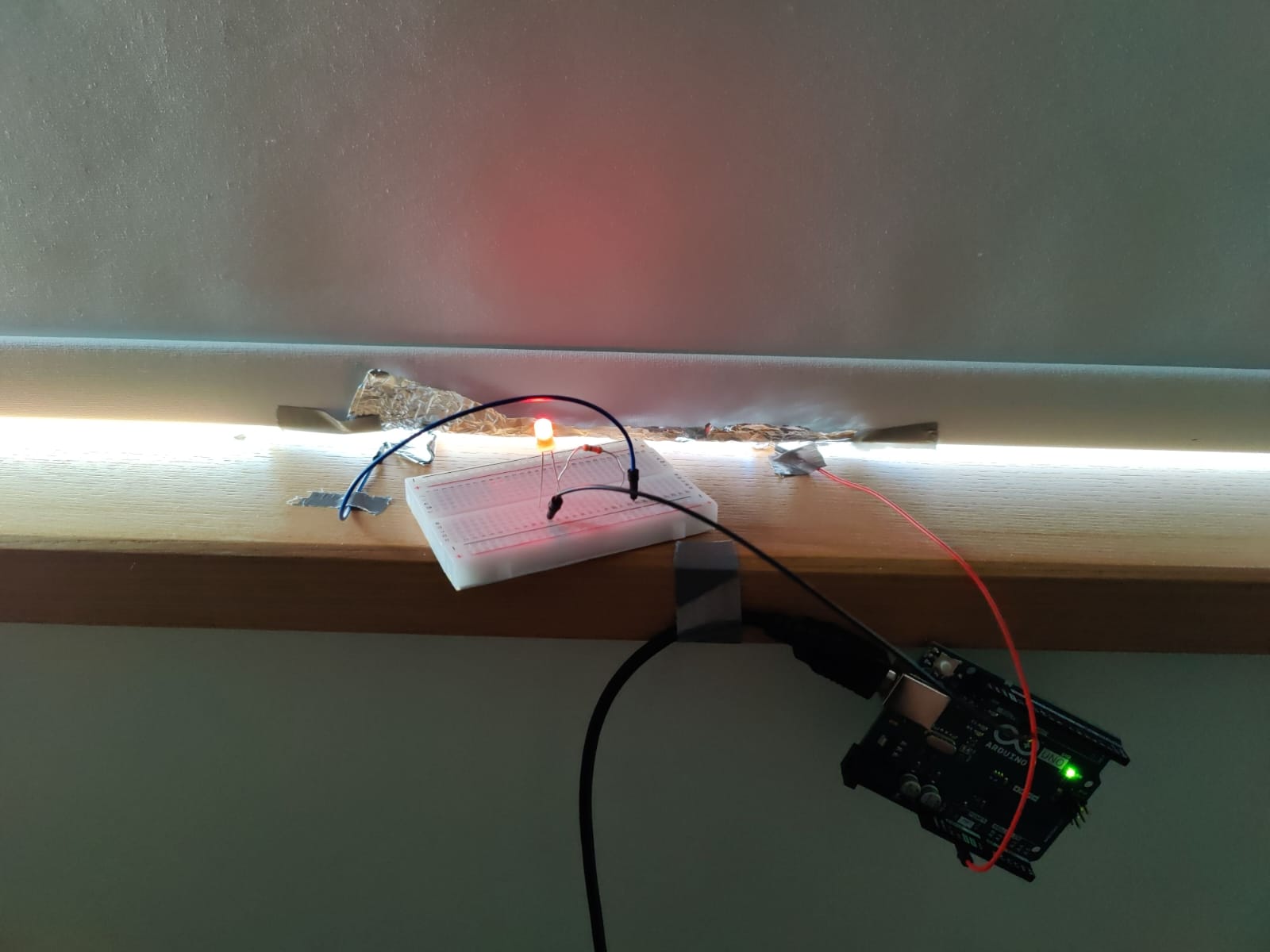
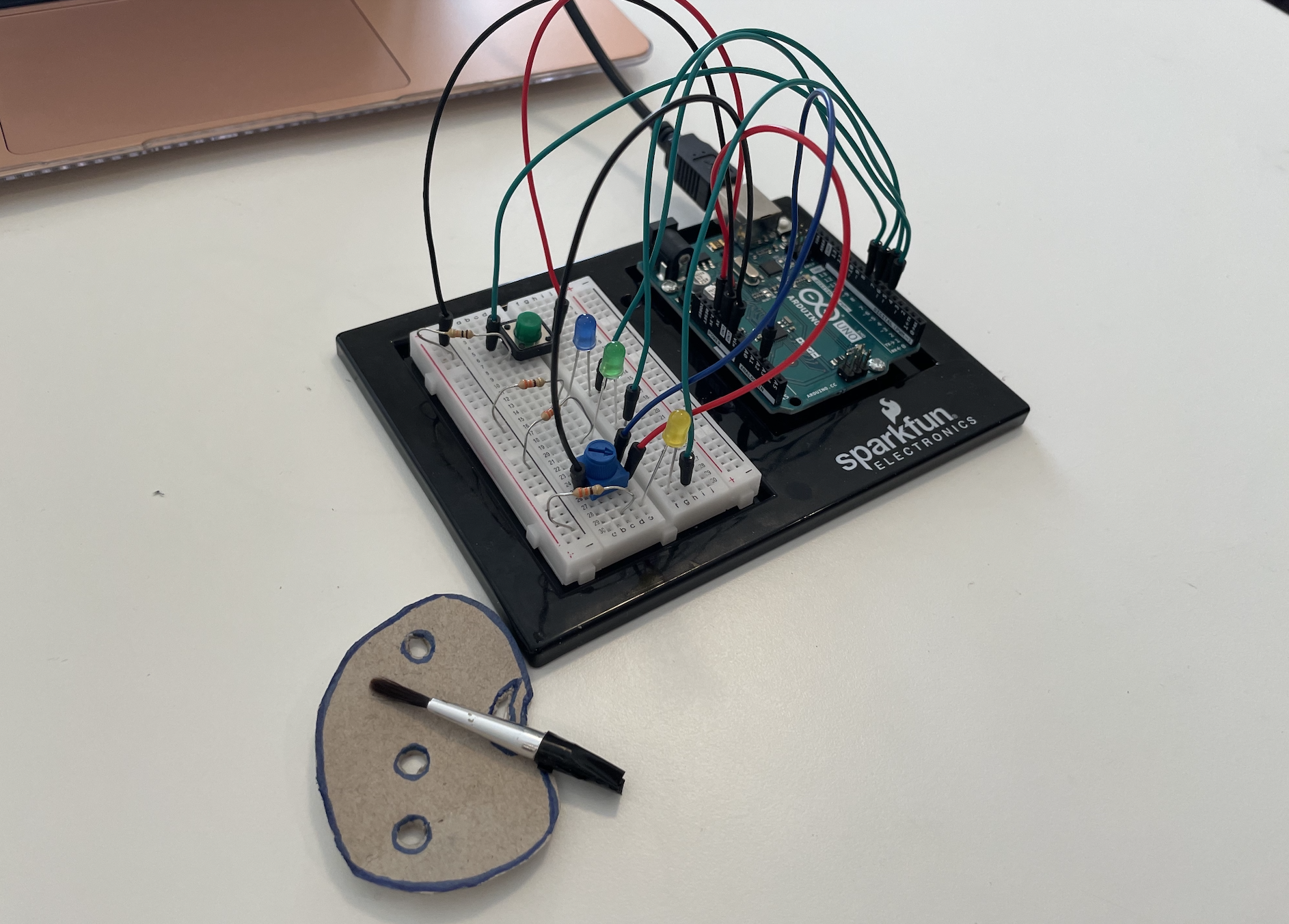
For this assignment, I started off by placing an LED and playing with the switch to control its blinking parameter. Gradually, I added two more LEDs to the circuit. And controlled them alternatively when the switch was switched on and off. After playing with it for a while, I decided to give it a whimsy twist to highlight the process of how we make secondary colors on the color palette when two primary colors get mixed. Hence, when a blue “colored” LED is mixed with a yellow “colored” LED, we get the green “color” or in other words, the switch controls the primary colors (blue and yellow) and the potentiometer creates the secondary color (green).
CODE AND CHALLENGES
It took me quite some time to figure out how three LEDs had to be controlled using a single switch in the code and then to alternate their blinking movements too. Initially, the three LEDs in the series were not switching on and off so I had to change the input value to INPUT_PULLUP.
int switchPin = 5;
 int led1Pin = 6;
 int led2Pin = 7;
 int led3Pin = 8;


void setup()
{
  pinMode(led1Pin, OUTPUT);
  pinMode(led2Pin, OUTPUT);
  pinMode(led3Pin, OUTPUT);
  pinMode(switchPin, INPUT_PULLUP);

}
void loop()
{
  byte buttonState = digitalRead(switchPin);

  if (buttonState == LOW) {
    digitalWrite(led1Pin, HIGH);
    digitalWrite(led2Pin, LOW);
    digitalWrite(led3Pin, HIGH);
  }
  else if (buttonState != LOW){
    digitalWrite(led1Pin, LOW);
    digitalWrite(led2Pin, HIGH);
    digitalWrite(led3Pin, LOW);
}
}
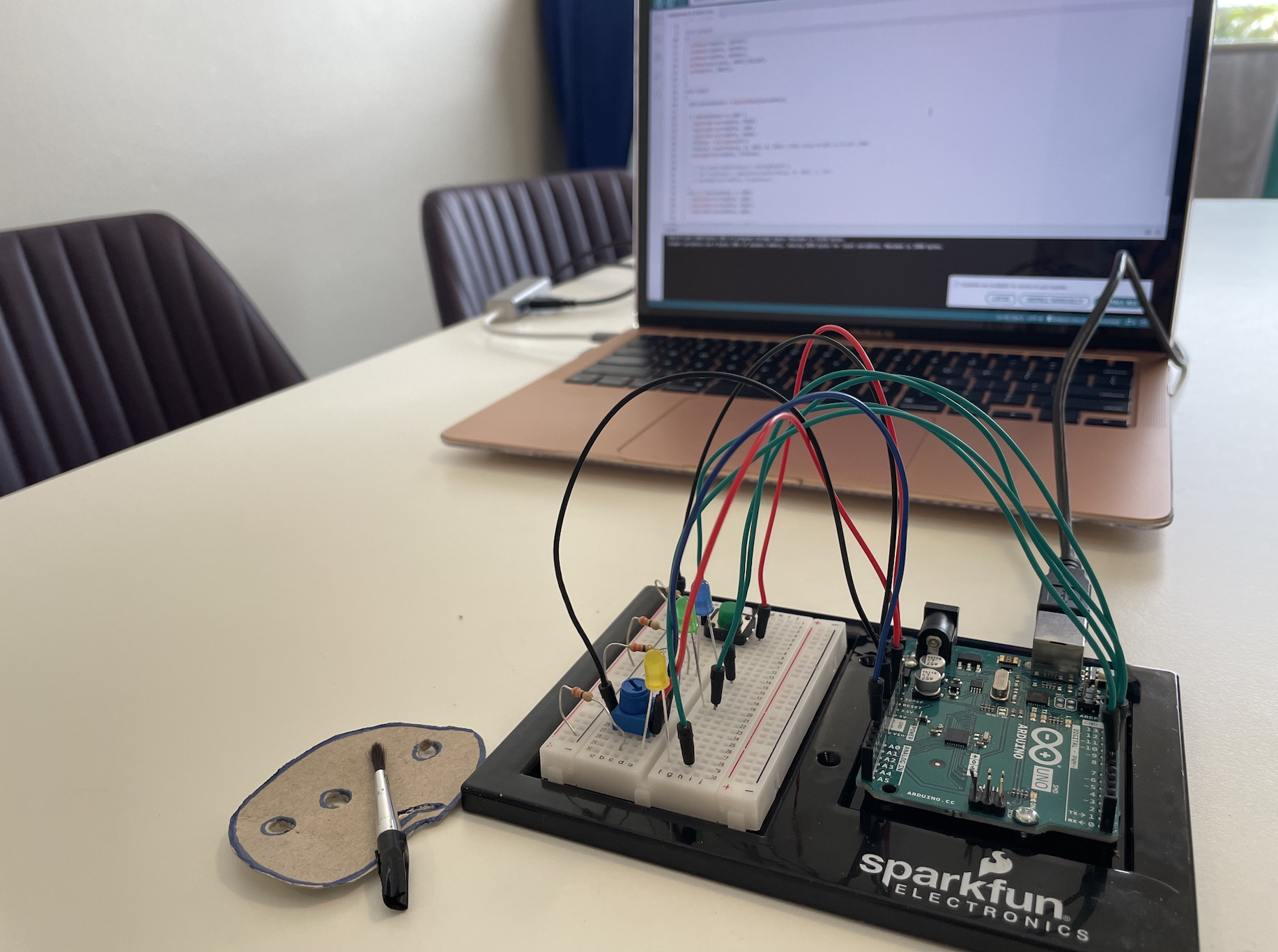
Secondly, connecting the potentiometer to control the green LED’s brightness through an analog input was a task too. It was either the switch or the potentiometer that was controlling the LEDs, I had to code them in the same button state if-else conditional to get them to work together.
else if (buttonState == LOW) {
//     int prValue = analogRead(Pr);
//     int brightness = map(prValue, 0, 1023, 0, 255);
//     analogWrite(led3Pin, brightness);
//   }
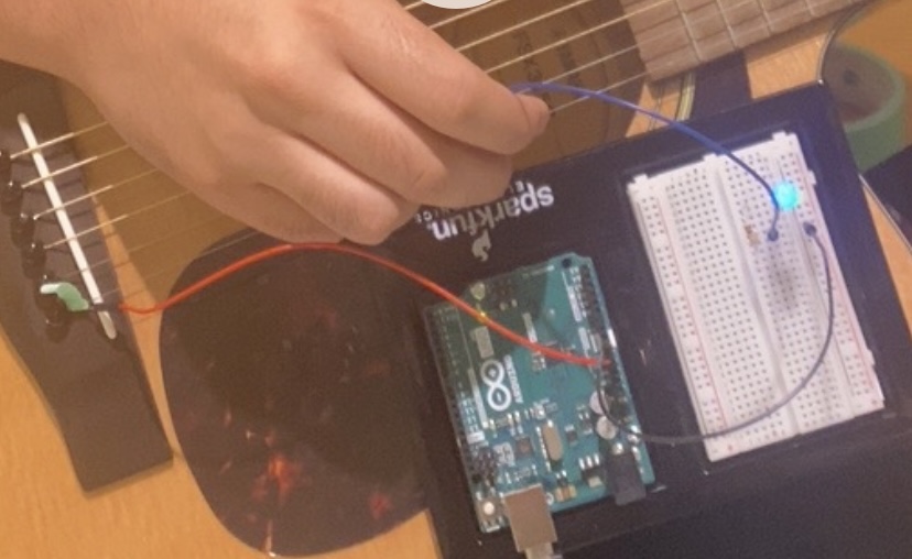
Here is the artist session!

REFLECTIONS
Since I coded in C++ for the first time, I had to go through multiple tutorials to finalize my code. I am happy with the final outcome but would also like to further experiment with analog and sensor switches separately before putting them together. The animation is still very simple, but I would also like to work a bit more on them for example make the first LED blink once, the second LED twice, and so on. I did try to incorporate these cases in my project through delay() but was not able to do so while connecting both sensory and analog switches.