
Concept
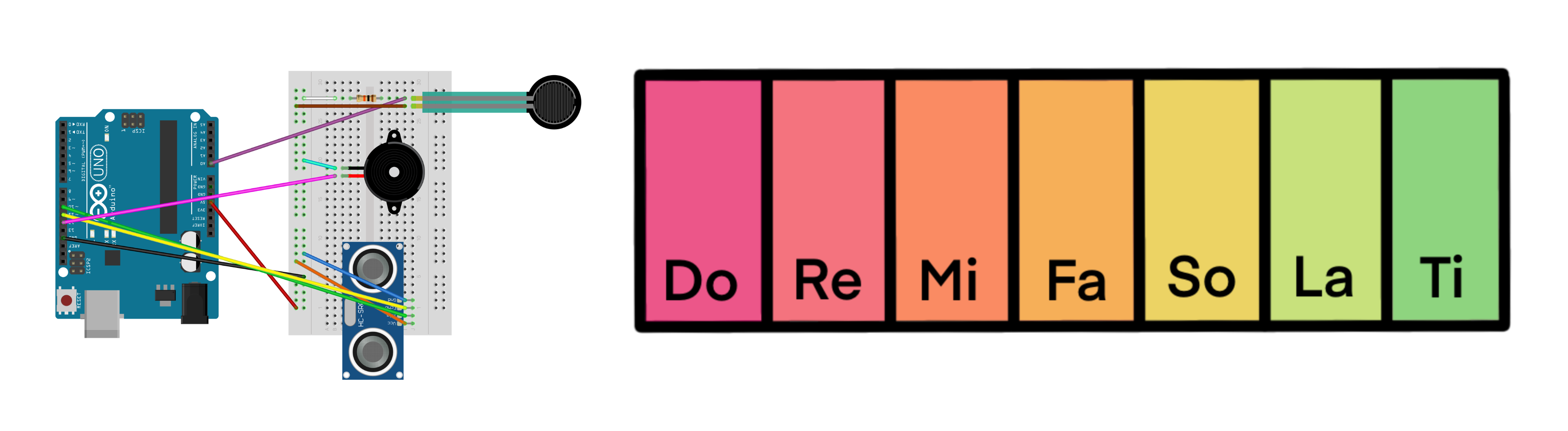
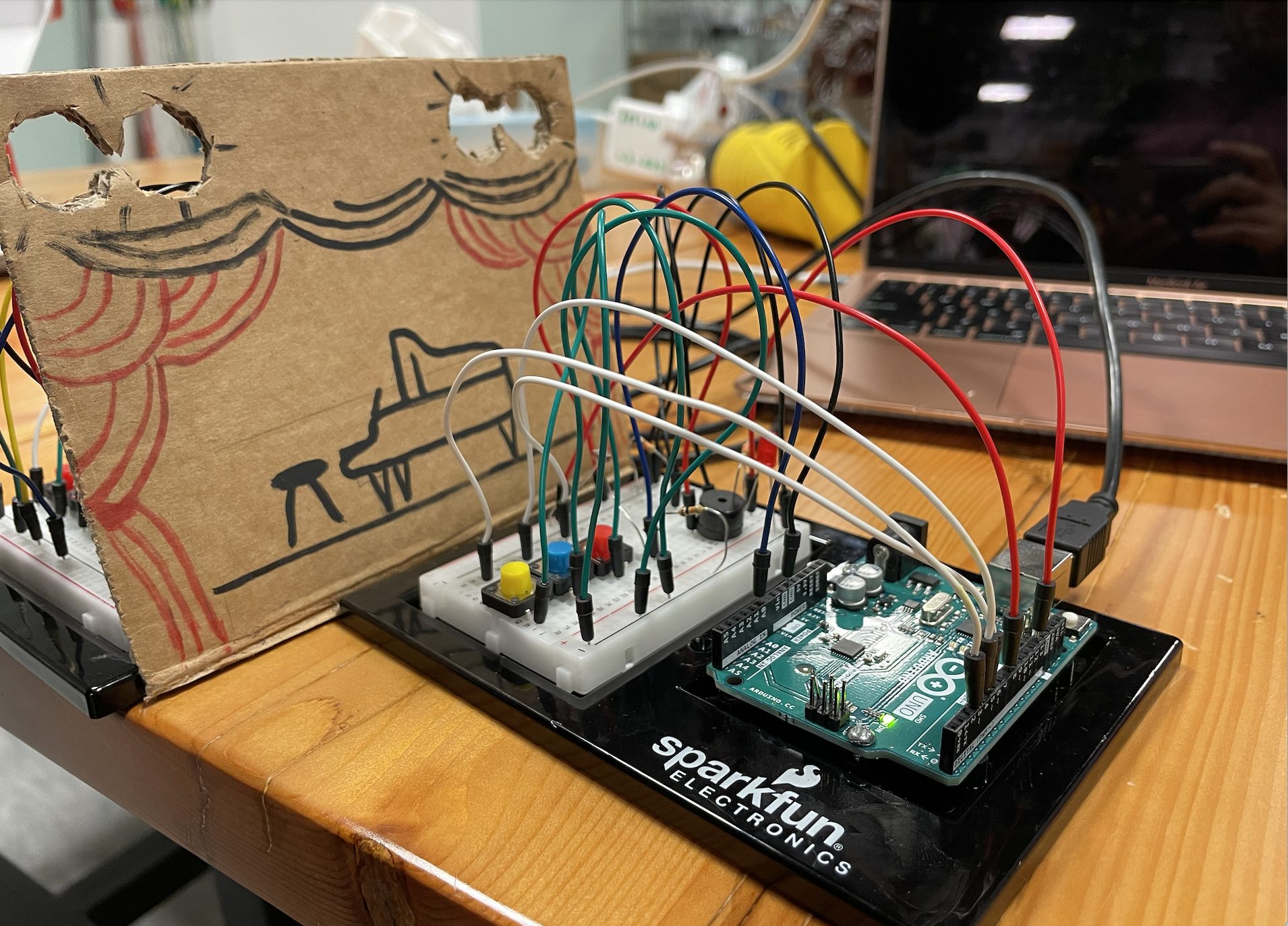
For this week’s assignment, [Daniel] and I constructed a musical instrument that measures the distance between the ultrasonic sensor and anything placed in front of it (i.e., your hand). Depending on how far you place your hand/ an object from the sensor, the piezo buzzer will play one of 8 different notes we inputted into the code.
To do this, we used a force sensing resistor that you had to press on whenever you wanted the ultrasonic sensor to detect your hand, and a piezo buzzer that would play the sound as output.
Arduino: How to Make an Instrument
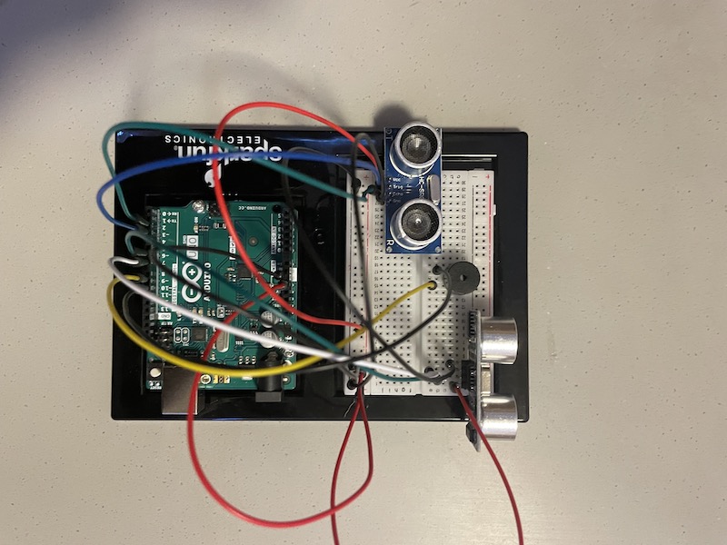
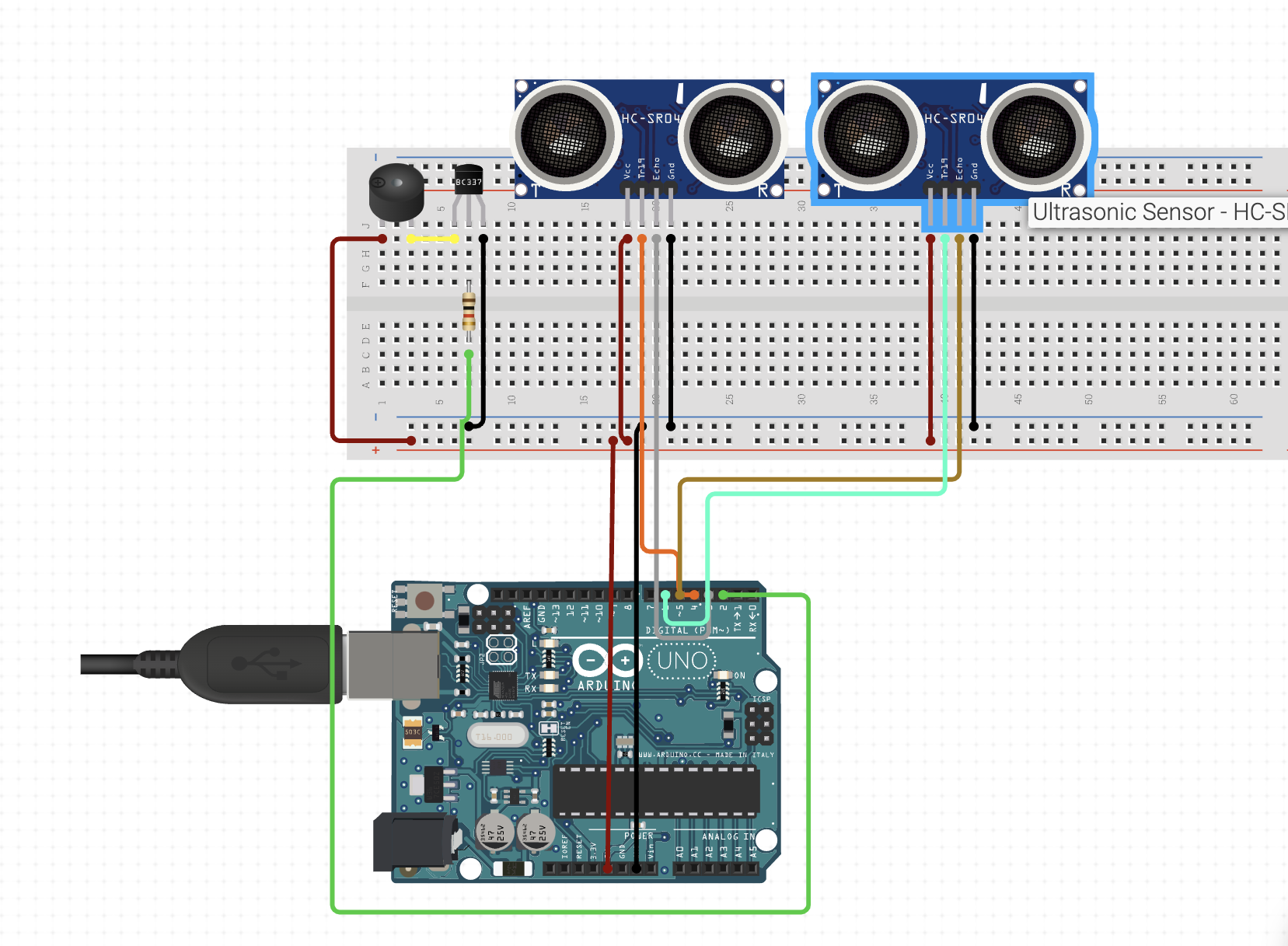
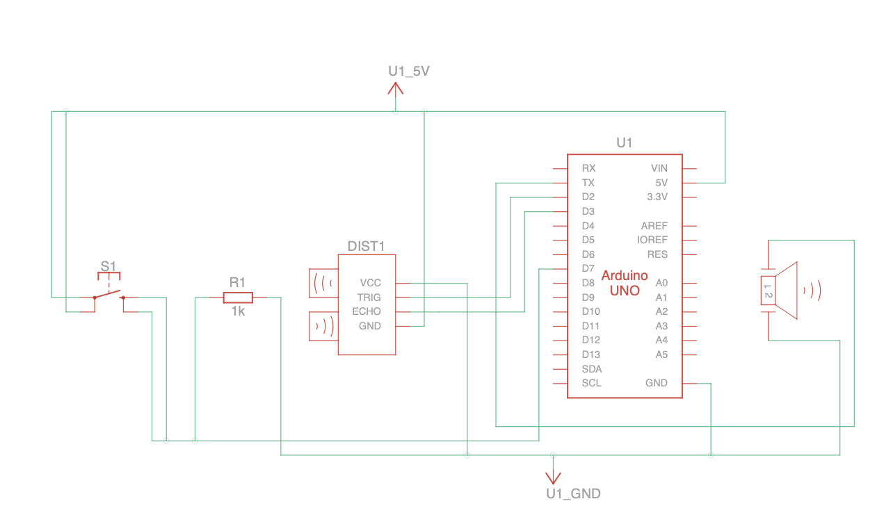
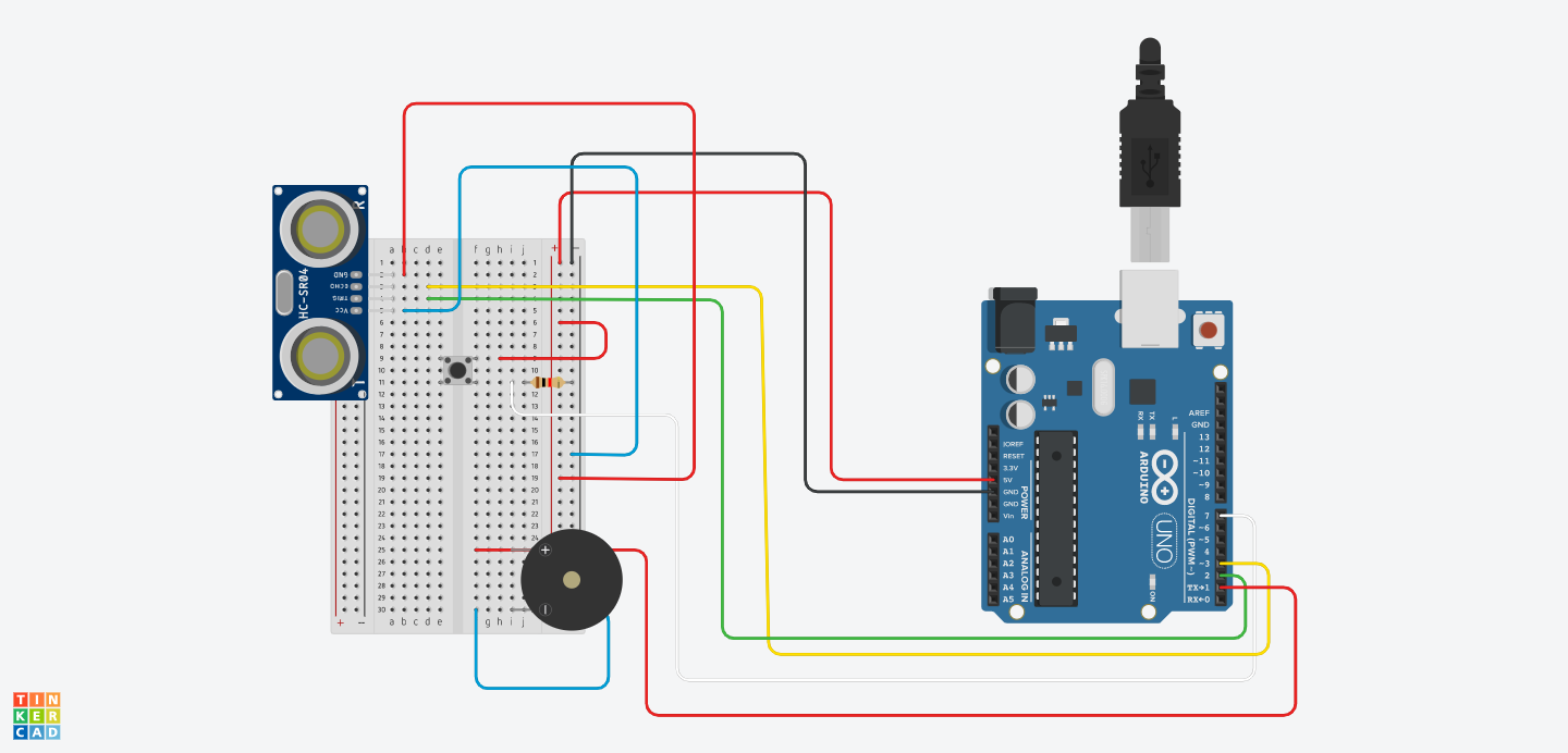
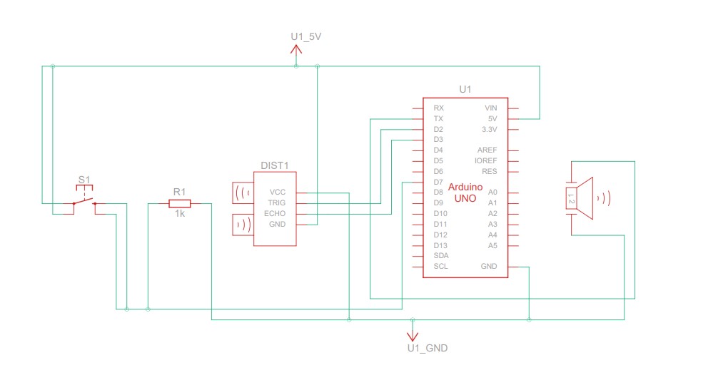
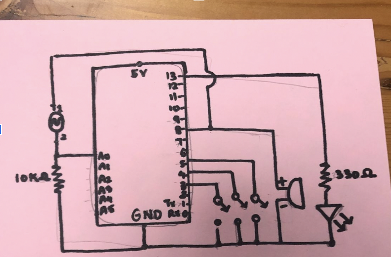
Schematic and Images
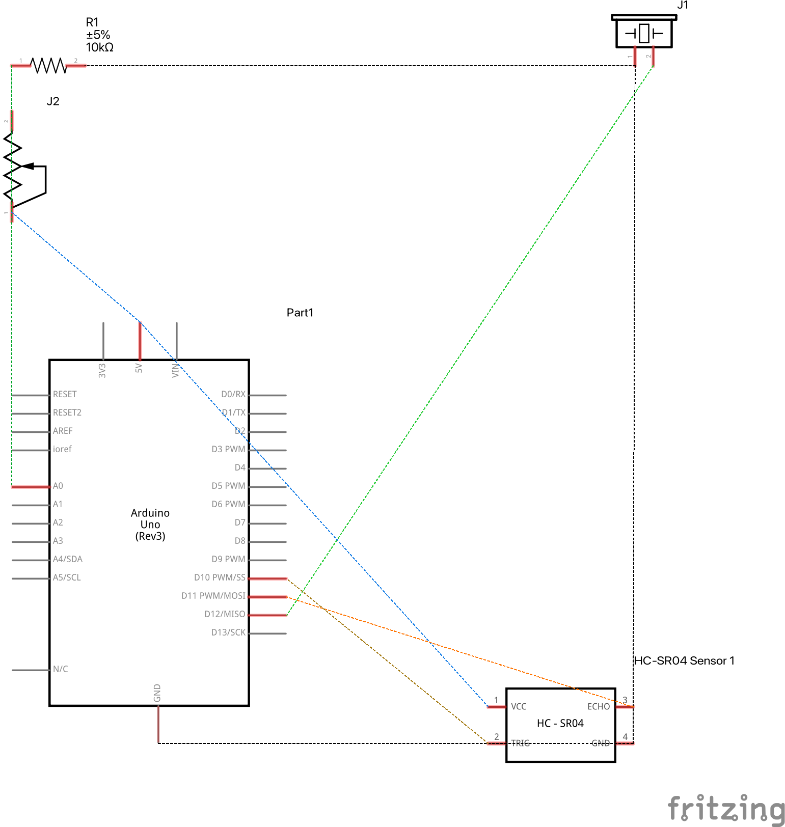
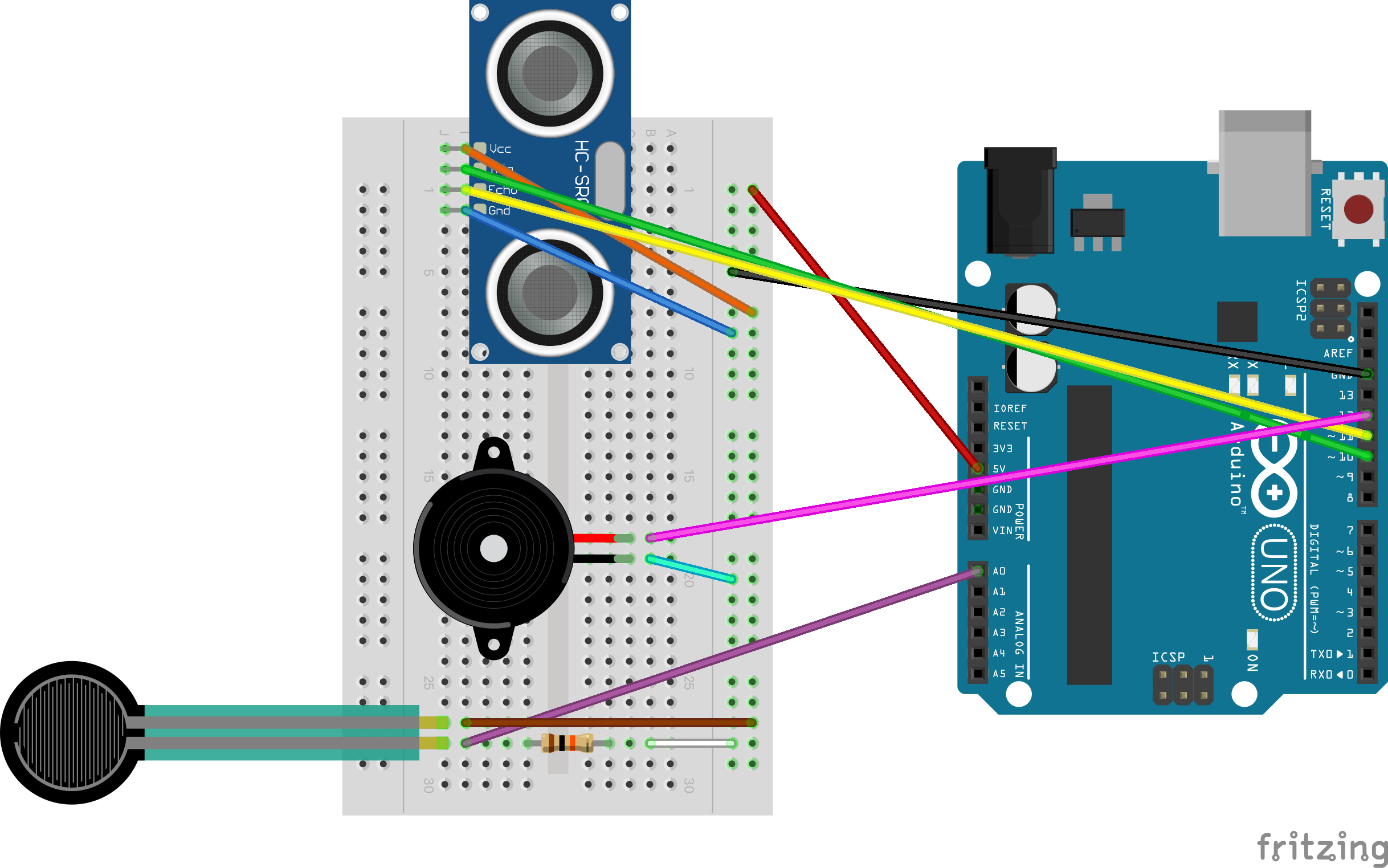
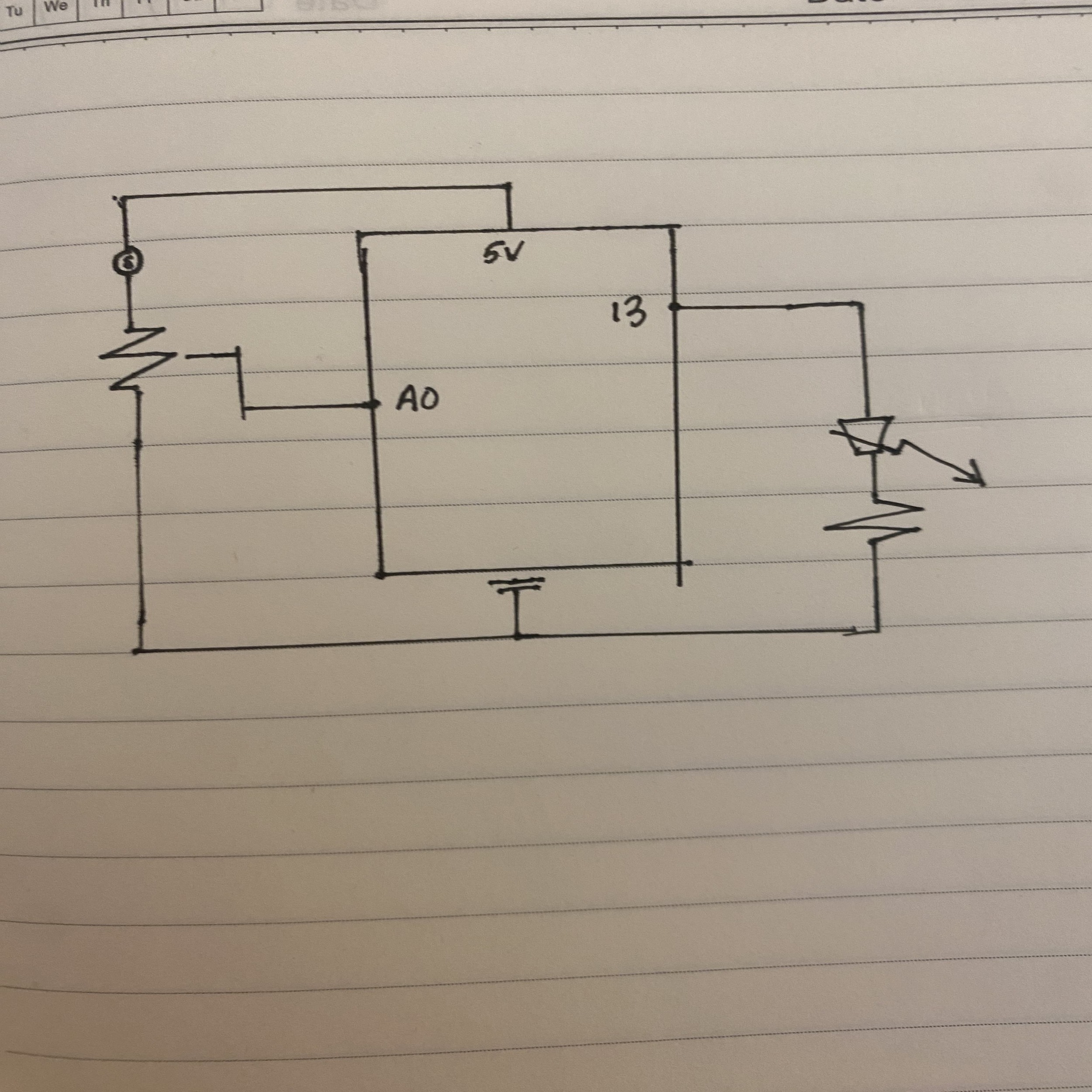
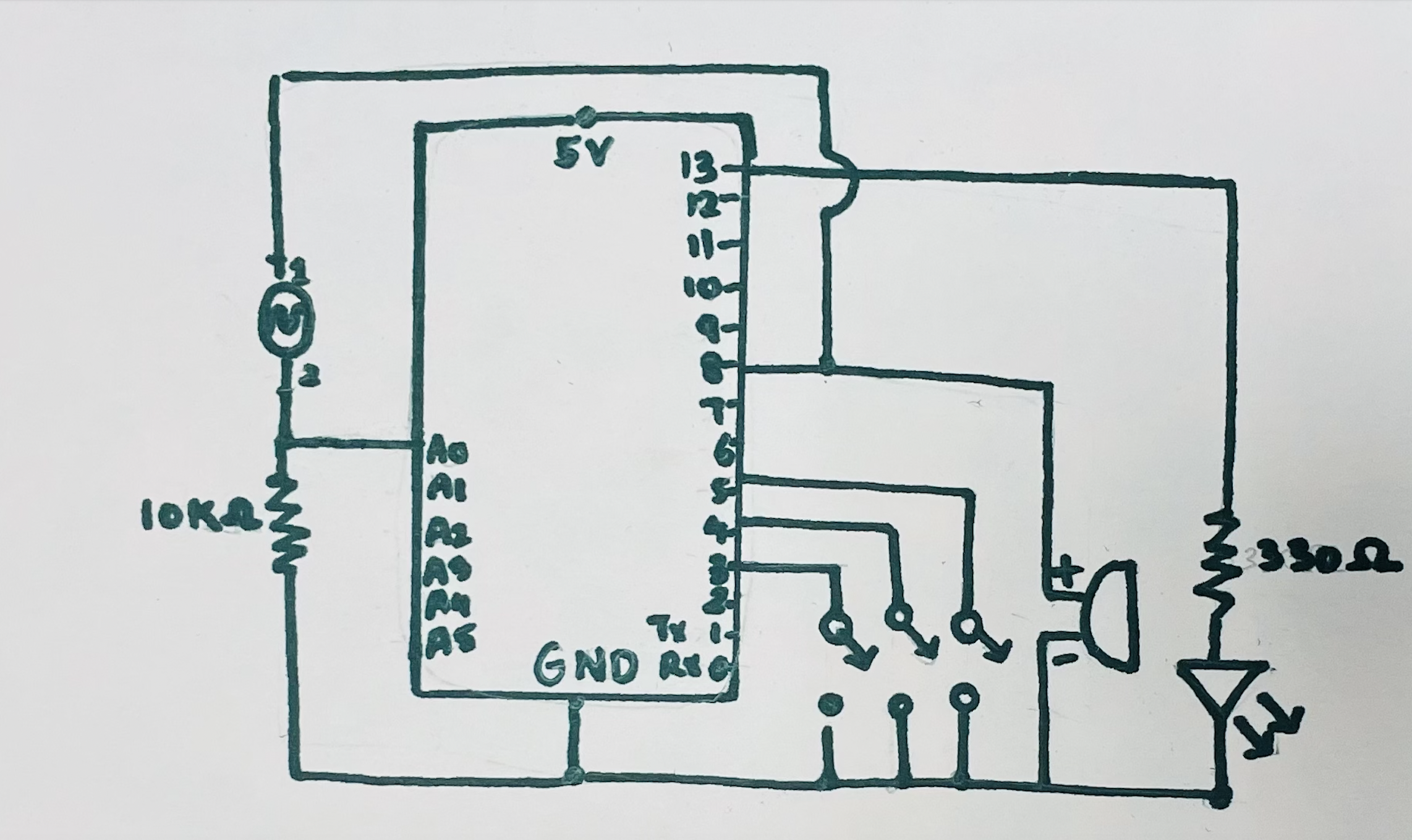
Here is the schematic for the circuit:
Code (or code highlight?)
int trig = 10; // digital 10
int echo = 11; // digital 11
long duration;
long distance;
int force;


void setup() {
 // runs once
 pinMode(echo, INPUT); // digital 11
 pinMode(trig, OUTPUT); // digital 10
 Serial.begin(9600); // open serial monitor to track
}

void loop() {
 // runs repeatedly
 digitalWrite(trig, LOW);
 delayMicroseconds(2);
 digitalWrite(trig, HIGH);
 delayMicroseconds(10);
 digitalWrite(trig, LOW);
 duration = pulseIn(echo, HIGH);
 distance = (duration / 2 * 0.0344);

 int notes[7] = {233, 261, 293, 311, 349, 392, 440};
 //              Bb    C   D     Eb    F   G   A

 force = analogRead(A0); // analog 0

 if (distance < 0 || distance > 50 || force < 100){
   noTone(12);

 } else if (force > 100){
   int sound = map (distance, 0, 50, 0, 7);
   tone(12, notes[sound]);

 }
}
The notes were based on the key of Bb, as we intended to make Bohemian Rhapsody first, the notes and values are:
Bb: 233
C: 261
D: 293
Eb: 311
F: 349
G: 392
A: 440
Video:
Here I’m playing Twinkle Twinkle Little Star using the instrument.
Reflection and improvements:
- The ultrasonic sensor was very sensitive to movement very close to it, but the farthest note (A), was very hard to detect just because it was so far away from the sensor. This made the sound laggy when it came out of the piezo buzzer, which made the song sound very untuned and the note inconsistent.
- It may also be because of the quality of the sensor, but the range seemed too limited and not so accurate. If we tried to make it a shorter distance between frequencies, then it would have a lot of sliding, and if we wanted to keep the same distance apart we would have needed to move it further and cause a much more unstable sound

