As of this week, we had some tweaks to the concept of our whole idea. The idea will now center on connecting two people and two lamps to a single computer. This week has been filled with a range of challenges that have put our knowledge of Arduino and p5js to the test. Integrating a touch sensor to send data from Arduino to p5js and collecting and transmitting several bytes of information from p5js to Arduino are some examples of the operations that fall under this category. Among the concept adjustments we made was to use regular wire serial communication between Arduino and p5js rather than relying on the use of a bluetooth module, which would have made the project more interesting.
PROGRESS
At the moment we are struggling with successfully sending RGB values from p5js to Arduino and eventually displaying them on the LED strip. As of now, when we transmit specified color values from p5js to Arduino, they are displayed on the LED strip as intended. However, only the color white is projected on the LED strip when we send any other RGB values. Additionally, the lights do not “cycle” through their respective patterns like they should. For example, when we chose “flicker”, the lights flicker once and remain off, instead of flickering continuously as intended in the Arduino code. We started by doing a number of comprehensive tests to rule out the possibility that the issue could be with the serial transmission. The only remaining hypotheses for the bugs that we are still investigating are if the problem could be caused by using the jpg color wheel to determine color values or whether there are more mechanisms involving how Arduino interacts with LED strips that we need to comprehend. The below is a compilation of test-related videos:
(lights only showing white and not looping continuously)
(testing the color printed in the console vs the color that appeared to be chosen from the wheel and seeing that they two colors do not match up)
SOLUTION
After several hours of debugging, we found that using an image to pick the color just wasn’t working. We determined our hypothesis to be correct – that the issue was the values being sent by p5.js.
The mouse position was taking pixels from the original image and it was not being remapped to the resized and re positioned image we had in our code, even after applying the map function and several iterations of repositioning/resizing the image. We believe that the example used ( link ) to create the color picker worked because the image IS the canvas, which is not the case for ours.
We decided on a new way for the user to select the color, which would be by having an object that flashes a different color every few seconds where the user can then press a key to “freeze” the object on the selected color. In our updated sketch, all possible colors have been predetermined by us, though the process of choosing the color is more engaging now.
After making this change, the values sent to Arduino were actually representative of the color that was chosen when pressing a key, and the color that is displayed on the LED’s is now accurate. However, this did not solve the issue of the lights not looping.
As of this week, we had some tweaks to the concept of our whole idea. The idea will now center on connecting two people and two lamps to a single computer. This week has been filled with a range of challenges that have put our knowledge of Arduino and p5js to the test. Integrating a touch sensor to send data from Arduino to p5js and collecting and transmitting several bytes of information from p5js to Arduino are some examples of the operations that fall under this category. Among the concept adjustments we made was to use regular wire serial communication between Arduino and p5js rather than relying on the use of a bluetooth module, which would have made the project more interesting.
PROGRESS
At the moment we are struggling with successfully sending RGB values from p5js to Arduino and eventually displaying them on the LED strip. As of now, when we transmit specified color values from p5js to Arduino, they are displayed on the LED strip as intended. However, only the color white is projected on the LED strip when we send any other RGB values. We started by doing a number of comprehensive tests to rule out the possibility that the issue could be with the serial transmission. The only remaining hypotheses for the bugs that we are still investigating are if the problem could be caused by using the jpg color wheel to determine color values or whether there are more mechanisms involving how Arduino interacts with LED strips that we need to comprehend. The below is a compilation of test-related videos:
SOLUTION
After several hours of debugging, we found that using an image to pick the color just wasn’t working. We determined our hypothesis to be correct – that the issue was the values being sent by p5.js.
The mouse position was taking pixels from the original image and it was not being remapped to the resized and re positioned image we had in our code, even after applying the map function and several iterations of repositioning/resizing the image. We believe that the example used ( link ) to create the color picker worked because the image IS the canvas, which is not the case for ours.
We decided on a new way for the user to select the color, which would be by having an object that flashes a different color every few seconds where the user can then press a key to “freeze” the object on the selected color. In our updated sketch, all possible colors have been predetermined by us, though the process of choosing the color is more engaging now.
After making this change, the values sent to Arduino were actually representative of the color that was chosen when pressing a key, and the color that is displayed on the LED’s is now accurate. However, this did not solve the issue of the lights not looping.
For this final project, I will be working with Ahmed as a group. We decided to go with our initial idea of making an interactive art piece. However, we considered what Professor Shiloh advised us during class when we shared our idea and started thinking about how we can make it more interactive and not lose the attention of our audience in 5 seconds. Before we started thinking more creatively, we were set on just making an art piece inspired by graphic art. Ahmed’s first post on this concept is linked here.
The art piece looks as if you are looking from above into a room filled with interactive walls. This digital art interacts with the user through mouse or sound control. Initially, we just wanted to replicate this same idea using p5.js and Arduino and make it come to life with materials in the IM Lab.
However, after taking into consideration what Professor Shiloh told us, which was that it would only keep the user entertained for a maximum of five seconds and need to come up with a way to make it more engaging, we did just that.
First, no more boring colorful blocks that look like walls. To be more aligned with our initial theme of depicting a living, breathing, organisms that reacts to different inputs, we have a more specific theme now: Stranger Things. If you are not familiar with stranger things, below is a trailer to season 1.
There are 4 seasons of stranger things now. The monsters that the group of kids fight are living, breathing organisms of some kind. The main things you and the user need to know is that one of the monsters on the show is called a Demogorgon. Below is a picture. The picture shows how it looks when it’s head is closed versus when it is open.
Closed Head vs Open Head (middle guy)
It kinds of looks like a very scary version of the Venus Flytrap plant.
At first, we were thinking of a plant/nature theme where we would depict some type of garden or collection of ferns or Venus Flytraps interacting with each other. It would have been more on the pretty nature side of things, but we thought Stranger Things could spice things up a little. We started looking for inspiration and we found this 3-D printed Demogorgon. We will only 3-D print the head and it would sit upright on the board we built. We plan on having the heads open and close as the user interacts with them through different mediums.
3-D printed Demogorgon. Inspiration.
Our interactive Demogorgon project will include speakers playing ominous music, flex sensors, an ultrasonic sensor, and big flaps of the monster’s head being controlled with Servo motors. Using these components, the user will be able to interact with the living, breathing Demogorgons and have a little fun with them.
To make the whole project even more immersive we created a narrative behind the Demogorgon and the user being able to choose to interact with it as the protagonist or the antagonist.
Description of Arduino program will do with each input and output and what it will send to and/or receive from P5
Using Adruino, we will be controlling the Servo Motors, and checking for any analog inputs from the flex and ultrasonic sensors. The sensor values are mapped to (0, 180) using the following section of code:
  OutsideFlexValue = analogRead(OutsideFlexPin);
  delay(15); //adding slight delays to make it stable

  InnerFlexValue = analogRead(InsideFlexPin);
  delay(15);

  servoPositionOutside = map(OutsideFlexValue, 24, 48, 45, 180);  // need it to rest at a midwards position

// int round10(int servoPositionOutside);

  servoPositionInside = map(InnerFlexValue, 24, 48, 45, 180);
It will send out a signal to the p5js program every time it hits a pre-determined threshold value. The out-sent value is to let the P5Js code know to play a growling sound along with the petals opening wide.
Description of what the P5 program will do and what it will send to and/or receive from Arduino
In order for the user to control or choose the interaction they would like to have with the Demogorgon, we will use p5.js. We will display an instruction screen followed by a digital button screen where the user can select presets and change between modes. For instance, the user will be able to choose between using the flex sensors with the glove or with the ultrasonic distance sensors to have different interactions with each.
From arduino it will receive the aforementioned serial communication to let it know when to play certain sounds.
Future Improvements:
Need to work on the mechanical aspect of the project more. The initial testing has shown that the servo motors cannot be used with a large armature due to force constraints.
The main problem we had from the start was that there was a lot of interference from the 5v pin on the Arduino which was causing the motors connected in parallel to jitter even when they were not being activated. We tried changing wires, changing components, making the digital pins far away as possible, and even using a different board but none of it worked.
Solution: The solution as the professor suggested was to use a separate battery to operate the servos with only digital PWM pins being connected to the board itself. This reduced the jitter to negligible.
As for my final project, I have decided to work on an interactive painting program that allows its users to draw on the p5js sketch. So far the progress has been slow and steady as it is a well-known fact that any piece of art takes time, haha.
The main Arduino components I have included in my circuit are two potentiometers. When they are toggled the ellipse starts creating a generative art in whichever direction the user chooses to move the analog sensors. Since the alpha and r values of the ellipse have been mapped, every time the speed of the potentiometer changes, depending on how fast or slow it goes, the transparency and the hue change. I have also included a switch which when pressed clears the screen.
function readSerial(data) {

  if (data != null) {
    // make sure there is actually a message
    // split the message
    let fromArduino = split(trim(data), ",");
    // if the right length, then proceed
    if (fromArduino.length == 3) {
      // only store values here
      // do everything with those values in the main draw loop
      rVal = fromArduino[0];
      alpha = fromArduino[1];
      buttonState = fromArduino[2];
    }


    //////////////////////////////////
    //SEND TO ARDUINO HERE (handshake)
    //////////////////////////////////
     let sendToArduino = left+ "," + right + "\n";
    writeSerial(sendToArduino);
  }
}
Arduino Code
void setup() {
  Serial.begin(9600);

   pinMode(2, INPUT);

  // start the handshake
  while (Serial.available() <= 0) {
    Serial.println("0,0"); // send a starting message
    // delay(300);            // wait 1/3 second
  }
}

void loop() {
  while (Serial.available()) {

    int left = Serial.parseInt();
    int right = Serial.parseInt();
    if (Serial.read() == '\n') {
      int sensor = analogRead(A0);
      delay(5);
      int sensor2 = analogRead(A1);
      delay(5);
      int button = digitalRead(2);
      Serial.print(sensor);
      Serial.print(',');
      Serial.print(sensor2);
      Serial.print(',');
      Serial.println(button);
    }
  }
}
Improvements
I am still working on a lot of components and hope to include them.
Add another switch that allows the user to shift between shapes such as from an ellipse to a square.
I want the values of the colors to change when the shape enters a certain side of the canvas while it is being controlled by the P5js.
Design a creative P5js interface than just plain background.
I am still working on designing a board wherein I could attach the switches and the potentiometers.
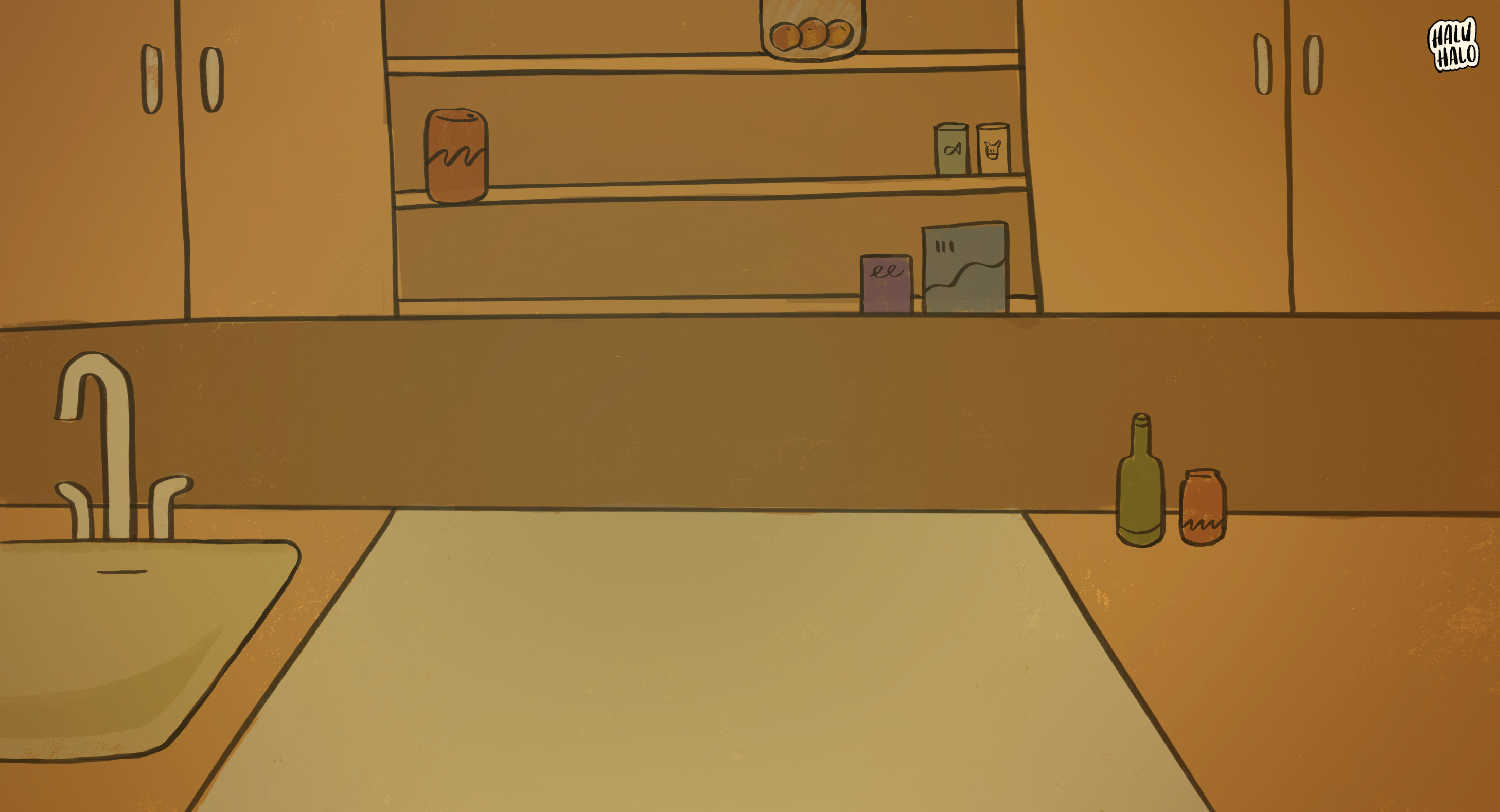
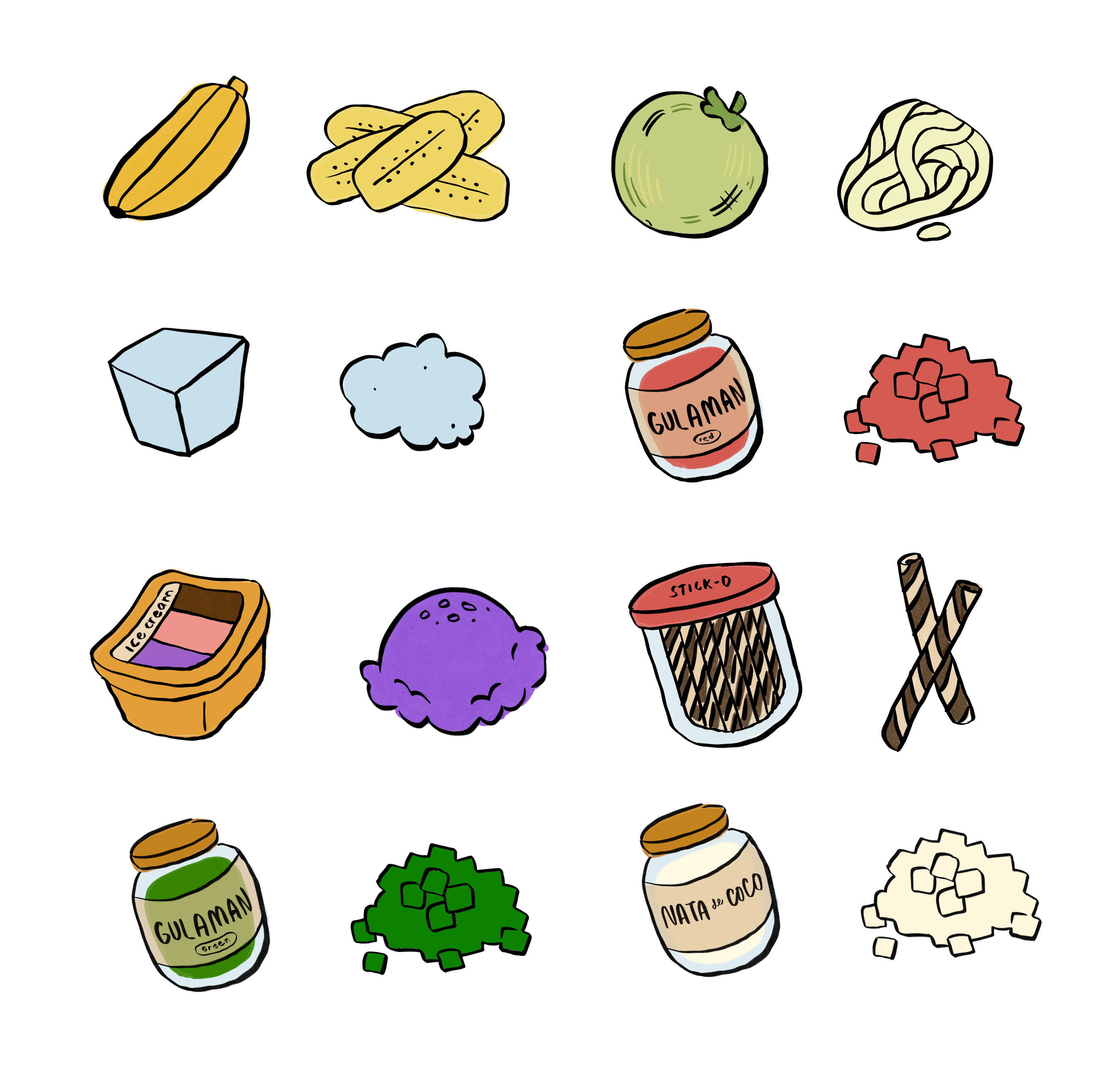
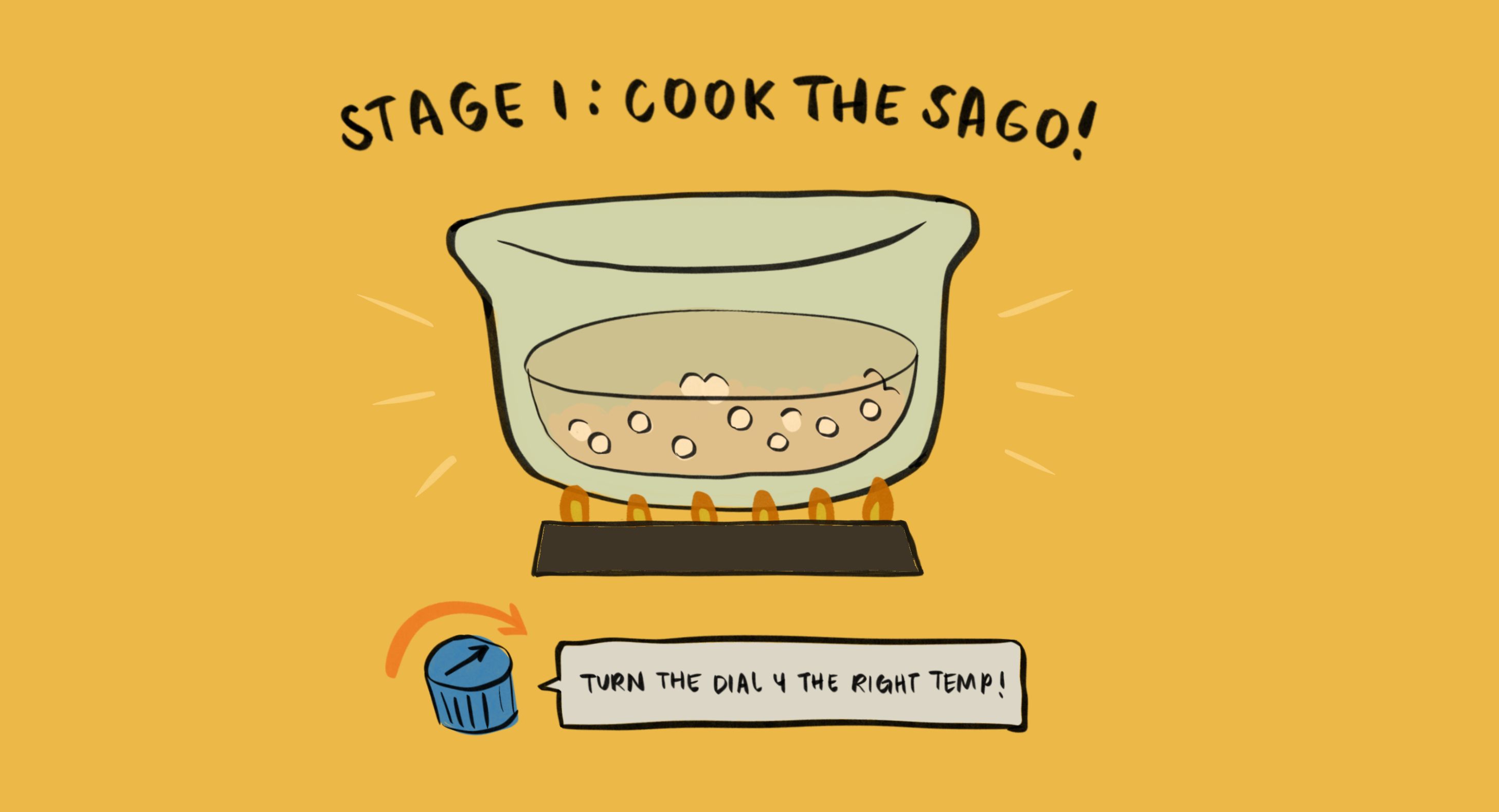
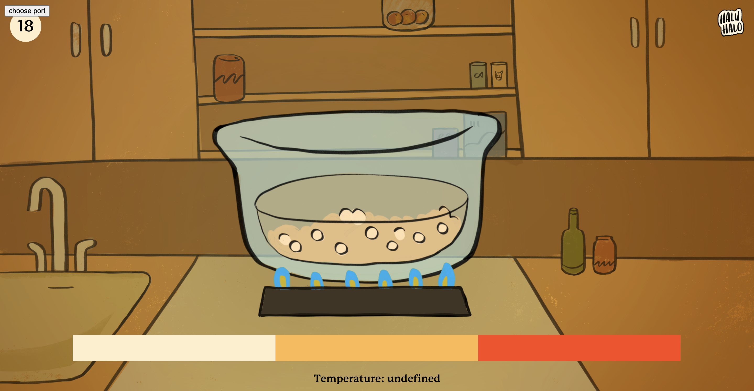
For my final project, I’m making a multi-stage cooking game for one of my favorite Filipino desserts, haluhalo.
So far, I’ve made quite a bit of art for the game. I’ve stuck to a style that’s more organic and colorful so that the art can feel more friendly and fun.
Here’s the sketch so far!
I’ve wired the digital switch and potentiometer, and I’ve implemented the potentiometer for Stage 1, so you can cook the sago if you hit the right temperature.
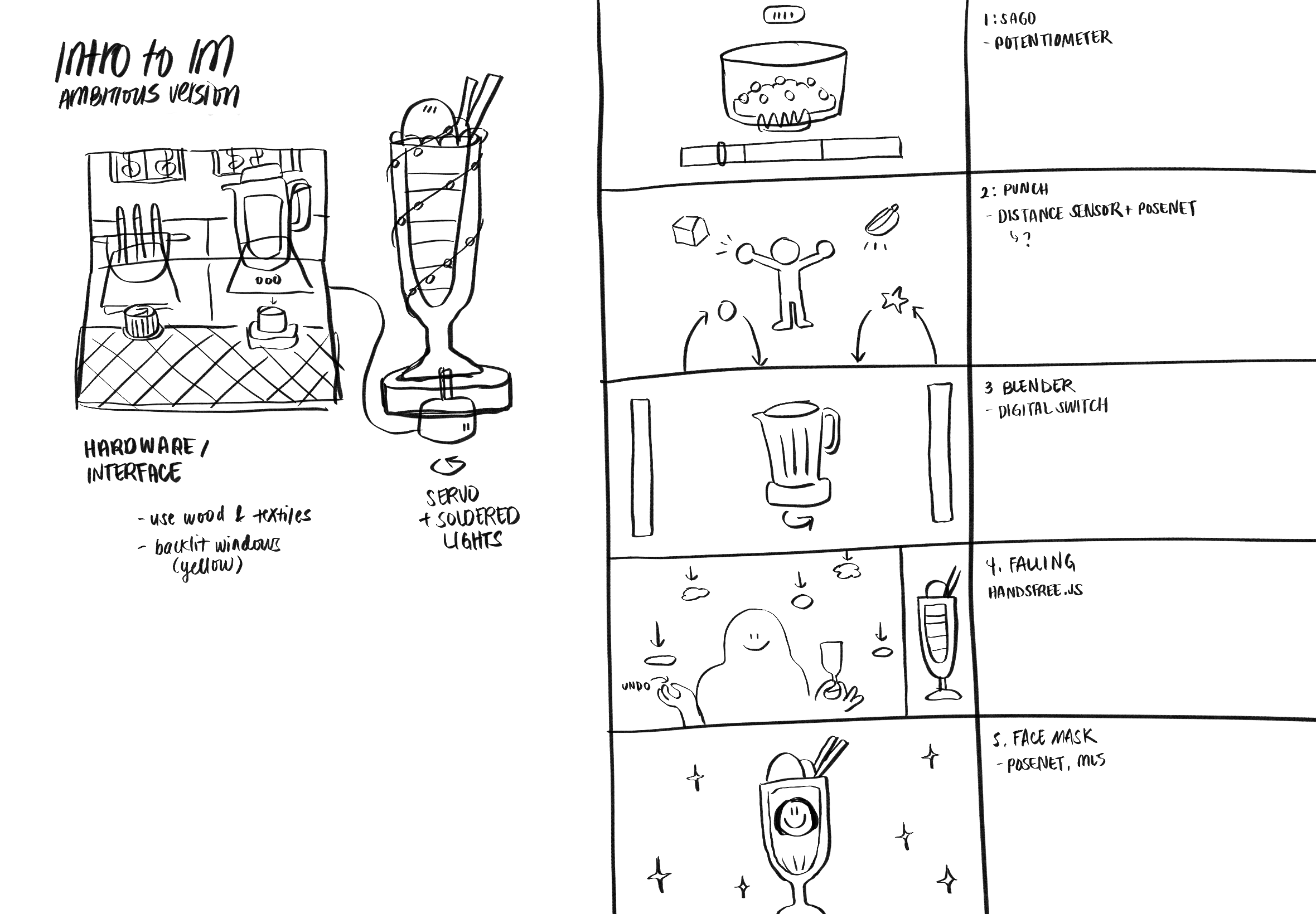
At first, I really hit a wall with this project and felt very tired of it, but the encouragement of other people really helped. After some reflection, I realized that I was feeling a bit tired because a lot of the work was just producing a lot of illustrations rather than more complex technologies that I hadn’t tried before.
As a result, I decided to try and make the project more ambitious, and to involve vectors, Handsfree.js, animations, interactivity, and maybe even some facial recognition and 3D via Three.js. Here is my revised plan.
I still have a lot to go, namely:
A lot of UI screens (failure and success) — I’m thinking of ways to make this less taxing or more reusable without losing the organic handdrawn vibe
Making the physical parts of the physical interface — I’m thinking of using wood and fabric rather than cardboard, and maybe 3D printing some of the more complex elements so they look more cool.
Making the Posenet, video, and Handsfree work :’DDDDD
It’ll be very terrible and very fun. I’m excited to post the next update!
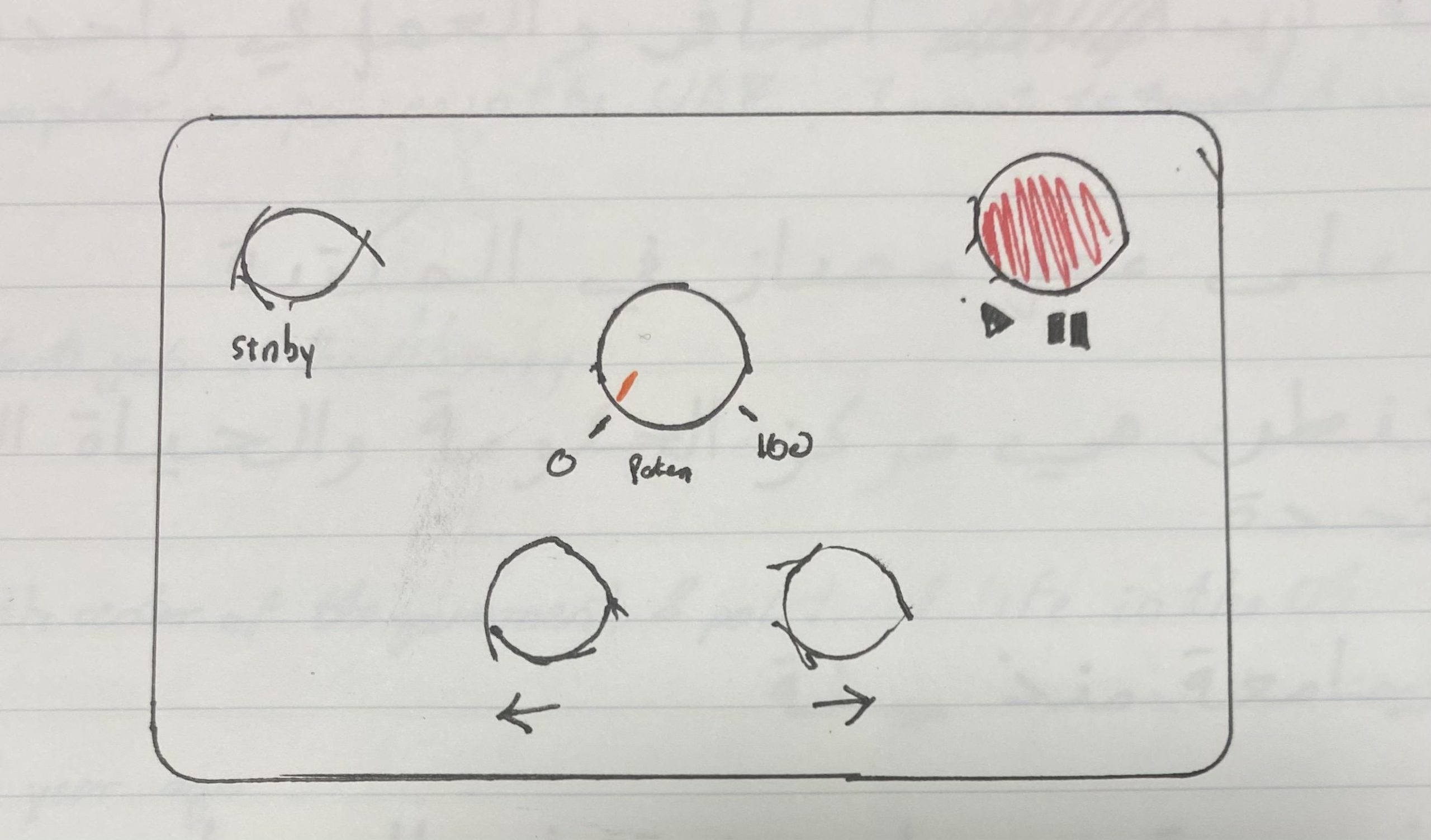
Our final project will be a mixer using an arduino board and P5js’ sound library.
DESIGN
The mixer will use the following components:
1 potentiometer – analog input (Will work like a slider would in an actual mixer)
2 buttons to switch between effects
1 button to work as a Pause/Play button
[MAYBE] 1 button to work as a Bypass/Standby function
Here is a sketch of what it would look like:
We will use the Arduino’s box to make the board and double as a place to hide the board.
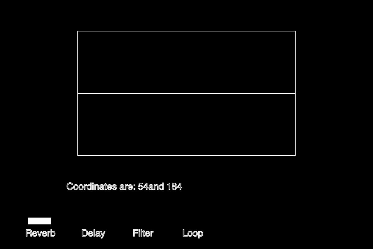
The interface where you will mix is looking like this, currently I am working on it and designing it, this is not the final product/result as we’d like to add some color to it:
The line at the middle will react to the sound and hopefully produce colors and make a sound wave.
FUTURE PLANS
During the week we expect to finish the interface and Arduino set-up, and would be working on the code and synching in the sounds.
Only project that may come is being able to translate the values from the potentiometer to the parameters to make the effects take effect.
Our final project will be a mixer using an arduino board and P5js’ sound library.
Design
The mixer will use the following components:
1 potentiometer – analog input (Will work like a slider would in an actual mixer)
2 buttons to switch between effects
1 button to work as a Pause/Play button
[MAYBE] 1 button to work as a Bypass/Standby function
Here is a sketch of what it would look like:
We will use the Arduino’s box to make the board and double as a place to hide the board.
The interface where you will mix is looking like this, currently I am working on it and designing it, this is not the final product/result as I’d like to add some color to it:
The line at the middle will react to the sound and hopefully produce colors and make a sound wave.
Future plans
During the week we expect to finish the interface and Arduino set-up, and would be working on the code and synching in the sounds.
Only project that may come is being able to translate the values from the potentiometer to the parameters to make the effects take effect.
In our last post we had come up with a game for our final project. After some further brainstorming, we thought it would be fun to try something other than a game, considering that this is what we did for our midterms. We thought about making an interactive system that could be experienced by multiple people at the same time. Our idea for the project is now to create a touchable “friendship lamp.” The basic idea is that we will build two lamps using two Arduino boards and LED strips. Each light will be equipped with different settings that can change the light pattern and color. These settings will be able to be manipulated within a program on p5.js, accessed on separate computers by the two users. After one user chooses the settings of their light, they then touch their lamp to send that light to the other user’s lamp. Communication between the two users can be simultaneous and there is no limit to the amount of times they can send each other messages.
THE ROLE OF P5.js
The sketch on p5.js will be a simple program with a few screens that allows the user to control the light they will send. They will be able to choose any color from a color wheel, and they will be able to choose from 3 different light modes: flicker, wave, and pulse. The choices made by the user will be stored by the program, and p5 will then send this data to the board of the other person’s lamp. However, data is not sent until some feedback is received from Arduino, explained in detail in the following section.
THE ROLE OF ARDUINO
A touch sensor and an LED strip would both be included in the Arduino circuit. When touched, the touch sensor transmits a signal to p5js, enabling p5js to transfer data to the Arduino board. Since p5js will be sending data about the color and pattern that the LED strip should light up in, the arduino board receives this data and turns the light on as requested by the user.
COMMUNICATION
As for the method of communication (serial mode) between the Arduino and p5js, we are still employing wires to transfer data back and forth at the time. However, because the two lamps and users in our original concept must be distanced from one another, we are exploring and, ideally, planning to include Bluetooth modules or, perhaps, an esp32 on our board to help with wireless communication between the two platforms.
PROGRESS
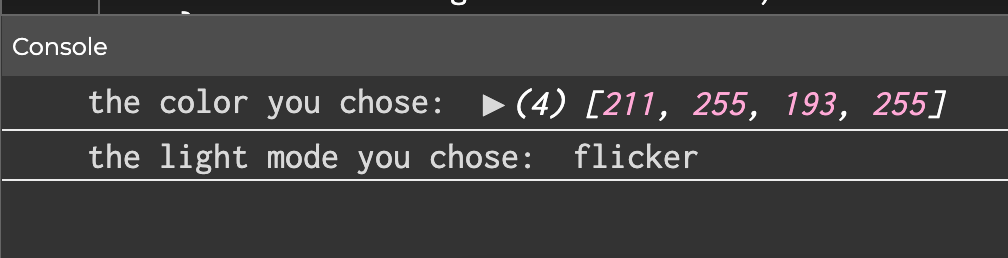
We knew that we weren’t going to be able to have cross communication between two users without wireless Arduino boards, and that we would not be able to implement the touching aspect without an actual tactile sensor. Hence, our plan for this week was to finalize our idea and begin assembling the different components of the system separately. The p5 program is almost complete, with an exception to the code that will send the data to the wireless Arduino board. The sketch is shown below:
At the end of the program, the console prints out the data that would theoretically be sent to Arduino. Including the color value and the light mode. Also, because we do not have the tactile sensor yet, the light is “sent” figuratively by just pressing any key in the third step.
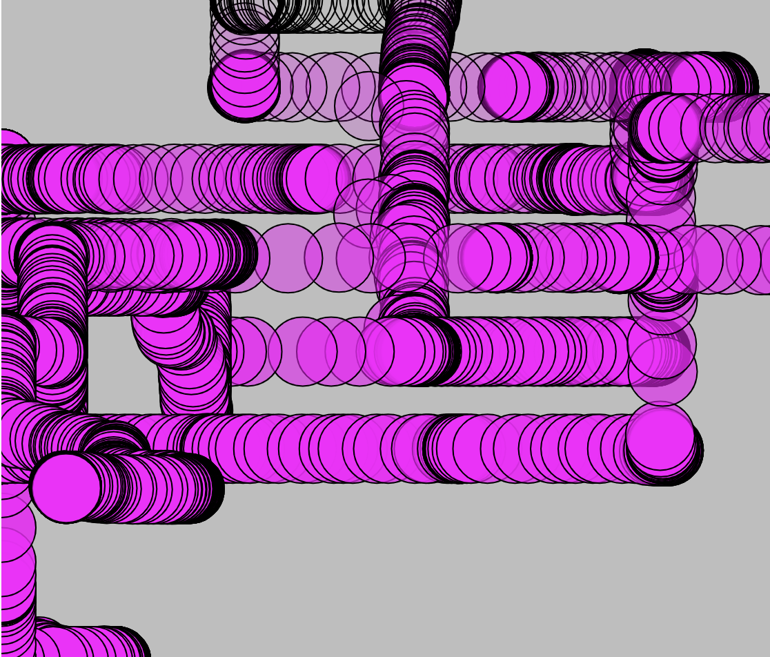
For the Arduino component, we built our strips of 10 LED’s for each lamp and connected them to a board and focused on simply creating three different light modes that could be controlled within the Arduino code, separate from p5. The code that demonstrates how the various light modes are used to enable a flicker, wavy, or fading effect on the LED strip is provided below:
void loop() {
  NeoPixel.clear(); // set all pixel colors to 'off'. It only takes effect if pixels.show() is called
  NeoPixel.show();
  // WAVY
  //turn pixels to green one by one with delay between each pixel
  for (int pixel = 0; pixel < NUM_PIXELS; pixel++) { // for each pixel
    NeoPixel.setPixelColor(pixel, NeoPixel.Color(0, 255, 0)); // it only takes effect if pixels.show() is called
    // if(pixel > 0)
    // {
    //   NeoPixel.show();   // send the updated pixel colors to the NeoPixel hardware.
    //   NeoPixel.clear();
    // }
    NeoPixel.show();   // send the updated pixel colors to the NeoPixel hardware.
    NeoPixel.clear();

    delay(100); // pause between each pixel
  }
  // turn off all pixels for two seconds
  NeoPixel.clear();
  NeoPixel.show(); // send the updated pixel colors to the NeoPixel hardware.
  delay(2000);     // off time
  // FLICKERING:
  //turn on all pixels to red at the same time for two seconds
  for (int pixel = 0; pixel < NUM_PIXELS; pixel++) { // for each pixel
    NeoPixel.setPixelColor(pixel, NeoPixel.Color(255, 0, 0)); // it only takes effect if pixels.show() is called
  }
  NeoPixel.show(); // send the updated pixel colors to the NeoPixel hardware.
  delay(500);     // on time
  // turn off all pixels for two seconds
  NeoPixel.clear();
  NeoPixel.show(); // send the updated pixel colors to the NeoPixel hardware.
  delay(500);     // off time
  //PULSING
  brighten();
  darken();
}
// 0 to 255
void brighten() {
  uint16_t i, j;
  for (j = 0; j < 255; j++) {
    for (i = 0; i < NeoPixel.numPixels(); i++) {
      NeoPixel.setPixelColor(i, 0, 0, j);
    }
    NeoPixel.show();
    delay(10);
  }
  //delay(100);
}
// 255 to 0
void darken() {
  Serial.begin(9600);
  uint16_t i, j;
  for (j = 255; j > 0; j--) {
    for (i = 0; i < NeoPixel.numPixels(); i++) {
      NeoPixel.setPixelColor(i, 0, 0, j);
    }
    NeoPixel.show();
    delay(10);
    Serial.println(j);
  }
  delay(100);
}
Finally, a demo of the different modes is displayed below:
For the project, we (Tim and Samyam) have decided to develop a system that lets the user sketch a diagram or shape on the p5.js canvas. This sketch then will be used to control the physical arm of our drawing platform. To accomplish this, we will send canvas data from p5.js to Arduino, controlling different parts of the drawing device.
The striking feature of the project is the interconnectivity of the drawing. The user can draw as many shapes or sketches as they desire, but everything will remain connected to each other. This idea is inspired by the Eulerian trail, where the floor is divided into multiple sections when multiple people step on it.
Hardware Design
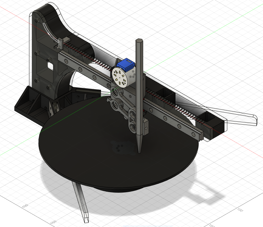
Following the previous post, we have finalized our concept to be a polar coordinate pen plotter that plots a shape drawn on the computer screen. Unlike our previous design, we have decided to make a 2-DOF system (linear movement on one axis, and rotational motion around an orthogonal axis). Although the mechanical design of the machine became more complex, this will make the software much simpler. For the design, we used Autodesk Fusion 360 to create a 3d model, which was manufactured with a 3d printer and a laser cutter. For the precision of the plotter, we purchased a linear guide rail, commonly used in CNC machines and 3d printers; we used a stepper motor for controlled movement. Below is a 3 d model design for the project:
A rack and pinion system was used, so as a gear connected to a stepper motor rotates, it will move the whole pen carrier along a linear rail.
One distinctive feature of this plotter is that the position of the rotating (base) plate can be adjusted freely. This allows the user to produce different drawings every time he or she moves the base plate.
Because drawings on the screen use cartesian coordinates, we had to convert XY coordinates into polar coordinates. This was very simple because T:(X,Y) –> (r, θ), where r = sqrt(x^2+y^2) and θ = tan^-1(y/x). r will determine the movement of a linear DOF and θ will determine how much the base plate will rotate. Do you see how simple the calculation got compared to the previous design?
Making Parts
As mentioned above, a laser cutter and 3d printer was used to make parts.
Prototype
Laser Cutting
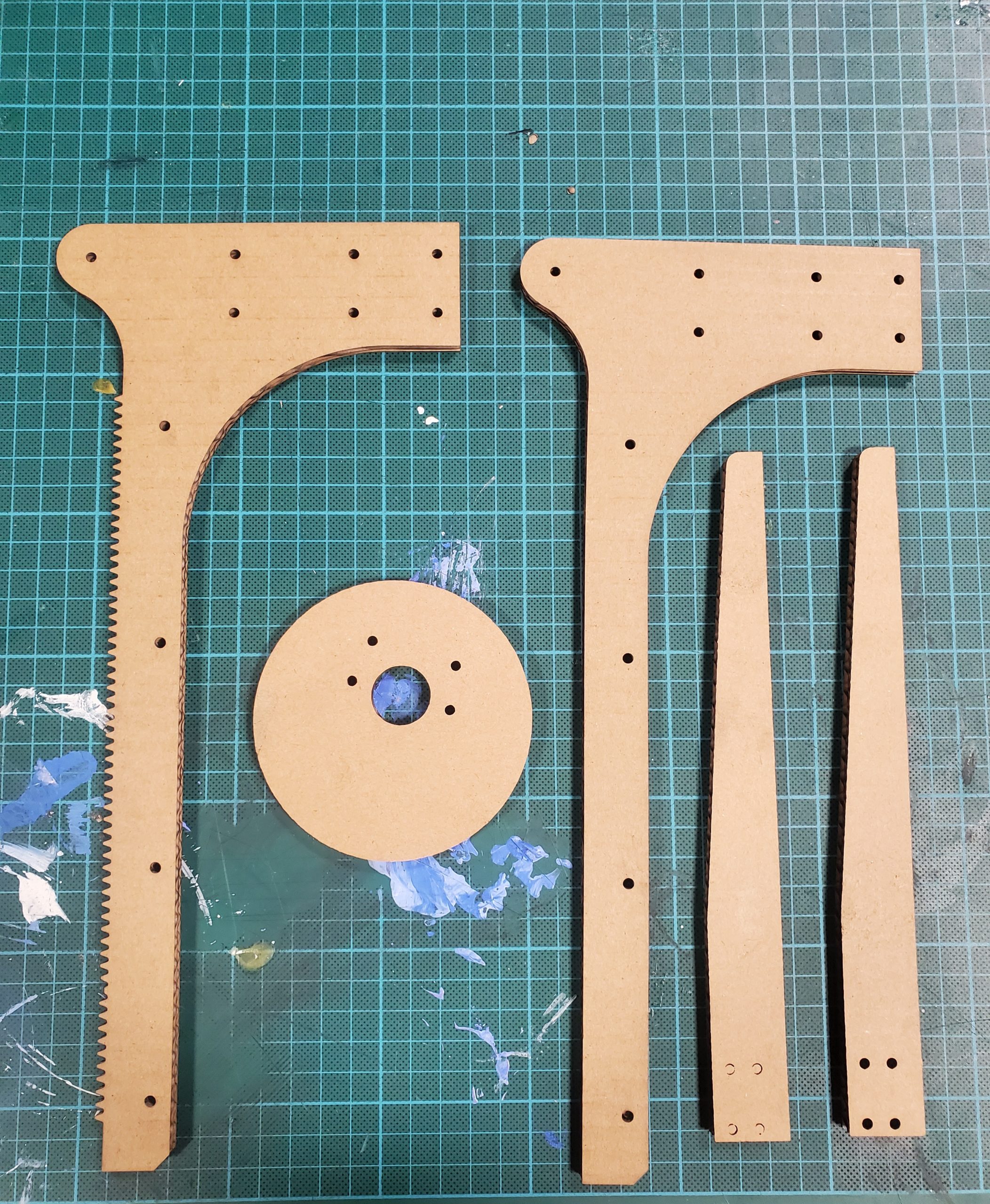
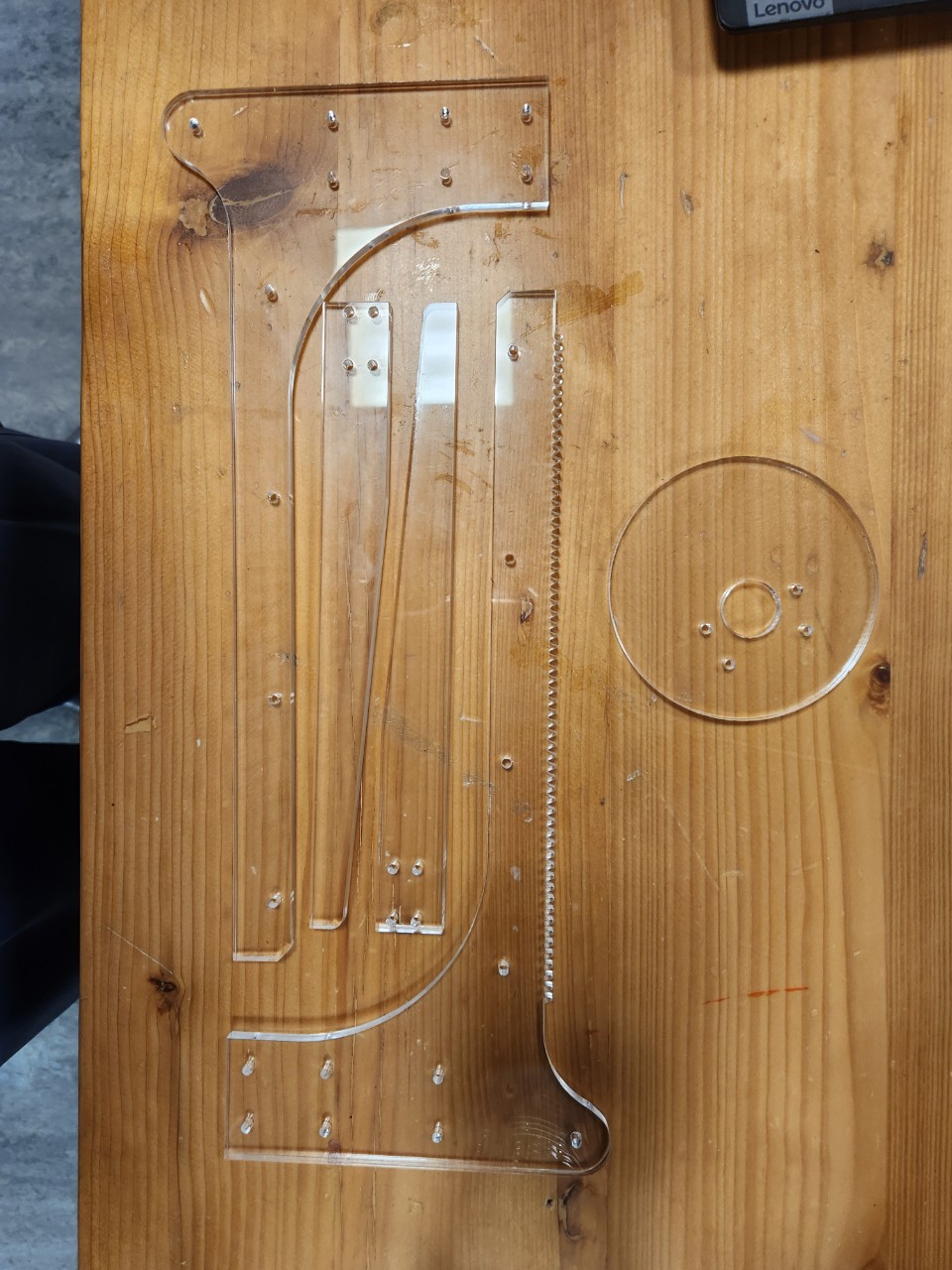
Due to the high rigidity of the acrylic plates, we decided to make the main body with acrylic parts. Based on our design, we were able to laser-cut the parts that we needed.
3D Printing
Parts that cannot be made with laser cutters were made using 3d printers. This included a base plate, a spacer between acrylic parts, and a pen moving mechanism.
P5.js Component
The preliminary phase of the project depends on the functionalities of the p5.js component. The user can use the mouse to draw shapes on the p5.js canvas; the shape will be replicated in the actual design using the Arduino component.
In order to sketch a shape on the canvas, the user can click the mouse and drag the cursor to draw the desired shape. This is regulated by two functions titled “mousePressed()” and “mouseReleased()” respectively. When the mouse is clicked, the global variable “isclicked” is set to True and when the mouse click is released, “isClicked” is set to False. This way, the global variable keeps track of the sketch being drawn.
Once the mouse is clicked, the program checks the position of the cursor – if it is static while being tracked, the position is ignored, i.e., the user must move the cursor, while the mouse is being clicked, so that a sketch can be drawn on the screen. It is facilitated by the following code:
// Make sure the mouse is clicked and cursor position is different
if (isClicked && mouseX !== pmouseX && mouseX !== pmouseY)
{
  // Create a vector and add it to the list
  // let pt = createVector(mouseX, mouseY);          // When origin is at the top-left corner
  let pt = createVector(mouseX - width/2, mouseY - height/2);
  positions.push(pt);
  // console.log(pt.x, pt.y);


  // Mapping Cartesian to Polar and appending it in mappedPositions array
  let temp_list = [];
  temp_list = cartToPolar(pt.x, pt.y)
  let pt_mapped = createVector((temp_list[0] * one_px_mm), temp_list[1]);
  mappedPositions.push(pt_mapped);

}
Here, we can see, if the aforementioned conditions are met, a new vector based on the cartesian location of the cursor is created and appended to the (global variable) list “positions”. The entire canvas is translated to the middle of the canvas, that’s why a certain amount is subtracted to the x and y coordinates before appending to the list. Similarly, with the help of a function titled “cartToPolar()”, each vector in the cartesian coordinates is converted to polar coordinates equivalent and appended to a list titled “mappedPositions[]”.
The program also consists of two manually coded buttons — RESET and SEND DATA. The former reset the canvas and resets the required variables so that the sketch can be redrawn from the beginning. While the latter is used to send data to the Arduino connected to the system. Both these functions derive from a template function titled “button()” that takes text, x, y coordinates, height and width of the button as arguments. To develop the SEND DATA functionality, a function named “send_data_button()” calls the main button function with the required parameters. The main function returns a boolean value [1 if the cursor is within the button and 0 otherwise]. If the boolean value is 1 and the button is pressed, the values in the “mappedPositions[]” list are forwarded to the Arduino using an inbuilt serial.write() function. In each iteration, the angle of the coordinate is transmitted following its radius.
function reset_button()
{
  let x = 26;
  let y = canvas_h - 70;
  let w = 125;
  let h = 50;

  // If the cursor is within the button button() function returns 1, else 0;
  let resetBool = button("RESET", x, y, w, h);

  // Resetting sketch if the cursor iswithin the button and mouse is clicked
  if (resetBool && mouseIsPressed)
  {
    positions = [];
    mappedPositions = [];
    isClicked = false;
  }

}
The p5.js component also comprises different functions like choosePort(), openPort(), serialEvent() and so forth to keep track of the port selection, data transmission as well as error handling.
Arduino Component
Arduino is connected to 2 stepper motors, each controlled by different stepper drivers. The Arduino will read data sent from p5js and move the pen and plate accordingly. Total of 2 switches will be connected to the board, both for homing the pen carrier (one push button and one limit switch).
When the button is pressed, the Arduino will begin to move the pen carrier back until the carrier hits the limit switch. Once the limit switch is closed, the Arduino will move the pen carrier slightly front and move the carrier back until it hits the switch again. The second part will be done at a much slower speed for accuracy. Homing a pen carrier is significant because the machine must always be aware of the pen’s current position. Homing allows the machine to always start from the same initial position.
This is the sample code showing how the code will work (no motors added yet):
const int limitSw = 7;

const int homeButt = 8;

long long currentTime = 0;

bool homing = false;

bool reachEnd = false;

void setup() {

  // put your setup code here, to run once:

  pinMode(limitSw, INPUT);

  pinMode(homeButt, INPUT);

  Serial.begin(9600);

}


void loop() {

  // put your main code here, to run repeatedly:

  if(!homing && digitalRead(homeButt) == 1){

    homing = true;

  }


  if(homing){

    if(!reachEnd){

      Serial.println("homing fast");

      if(digitalRead(limitSw) == 1){

        Serial.println("SW pressed");

        reachEnd = true;

        currentTime = millis();

      }

    }

    else{

      Serial.println("homing slow");

      if(digitalRead(limitSw) == 1 && millis() - currentTime > 500){

        Serial.println("SW slow pressed. homing complete");

        homing = false;

        reachEnd = false;

      }

    }

  }

}
The other part of the code will include moving each part accordingly to the coordinate values from p5js. This would be relatively easy to achieve because we can calculate how much each part will move in mm when the motor turns by half or a single step.
Further coding can be done once we are ready with fully assembled hardware.
Future Plan
The time it takes to 3D print parts is the only problem we are facing until now. Once we are done printing our parts, we will be able to assemble the parts together soon.
For now, the future plan includes the functionality to successfully coordinate the Arduino component with the data sent from the p5.js component. Since the canvas sketch is drawn based on cartesian coordinates, while the physical drawing is based on polar coordinates, we are planning to program the project so that artistic output is achieved.
Demo
The software phase of the project can be tested here using this link. The project will be completed once the printing phase is completed.
For the project, we (Tim and Samyam) have decided to develop a system that lets the user sketch a diagram or shape on the p5.js canvas. This sketch then will be used to control the physical arm of our drawing platform. To accomplish this, we will send canvas data from p5.js to Arduino, controlling different parts of the drawing device.
The striking feature of the project is the interconnectivity of the drawing. The user can draw as many shapes or sketches as they desire, but everything will remain connected to each other. This idea is inspired by the Eulerian trail, where the floor is divided into multiple sections when multiple people step on it.
Hardware Design
Following the previous post, we have finalized our concept to be a polar coordinate pen plotter that plots a shape drawn on the computer screen. Unlike our previous design, we have decided to make a 2-DOF system (linear movement on one axis, and rotational motion around an orthogonal axis). Although the mechanical design of the machine became more complex, this will make the software much simpler. For the design, we used Autodesk Fusion 360 to create a 3d model, which was manufactured with a 3d printer and a laser cutter. For the precision of the plotter, we purchased a linear guide rail, commonly used in CNC machines and 3d printers; we used a stepper motor for controlled movement. Below is a 3 d model design for the project:
A rack and pinion system was used, so as a gear connected to a stepper motor rotates, it will move the whole pen carrier along a linear rail.
One distinctive feature of this plotter is that the position of the rotating (base) plate can be adjusted freely. This allows the user to produce different drawings every time he or she moves the base plate.
Because drawings on the screen use cartesian coordinates, we had to convert XY coordinates into polar coordinates. This was very simple because T:(X,Y) –> (r, θ), where r = sqrt(x^2+y^2) and θ = tan^-1(y/x). r will determine the movement of a linear DOF and θ will determine how much the base plate will rotate. Do you see how simple the calculation got compared to the previous design?
Making Parts
As mentioned above, a laser cutter and 3d printer was used to make parts.
Prototype
Laser Cutting
Due to the high rigidity of the acrylic plates, we decided to make the main body with acrylic parts. Based on our design, we were able to laser-cut the parts that we needed.
3D Printing
Parts that cannot be made with laser cutters were made using 3d printers. This included a base plate, a spacer between acrylic parts, and a pen moving mechanism.
P5.js Component
The preliminary phase of the project depends on the functionalities of the p5.js component. The user can use the mouse to draw shapes on the p5.js canvas; the shape will be replicated in the actual design using the Arduino component.
In order to sketch a shape on the canvas, the user can click the mouse and drag the cursor to draw the desired shape. This is regulated by two functions titled “mousePressed()” and “mouseReleased()” respectively. When the mouse is clicked, the global variable “isclicked” is set to True and when the mouse click is released, “isClicked” is set to False. This way, the global variable keeps track of the sketch being drawn.
Once the mouse is clicked, the program checks the position of the cursor – if it is static while being tracked, the position is ignored, i.e., the user must move the cursor, while the mouse is being clicked, so that a sketch can be drawn on the screen. It is facilitated by the following code:
// Make sure the mouse is clicked and cursor position is different
if (isClicked && mouseX !== pmouseX && mouseX !== pmouseY)
{
  // Create a vector and add it to the list
  // let pt = createVector(mouseX, mouseY);          // When origin is at the top-left corner
  let pt = createVector(mouseX - width/2, mouseY - height/2);
  positions.push(pt);
  // console.log(pt.x, pt.y);


  // Mapping Cartesian to Polar and appending it in mappedPositions array
  let temp_list = [];
  temp_list = cartToPolar(pt.x, pt.y)
  let pt_mapped = createVector((temp_list[0] * one_px_mm), temp_list[1]);
  mappedPositions.push(pt_mapped);

}
Here, we can see, if the aforementioned conditions are met, a new vector based on the cartesian location of the cursor is created and appended to the (global variable) list “positions”. The entire canvas is translated to the middle of the canvas, that’s why a certain amount is subtracted to the x and y coordinates before appending to the list. Similarly, with the help of a function titled “cartToPolar()”, each vector in the cartesian coordinates is converted to polar coordinates equivalent and appended to a list titled “mappedPositions[]”.
The program also consists of two manually coded buttons — RESET and SEND DATA. The former reset the canvas and resets the required variables so that the sketch can be redrawn from the beginning. While the latter is used to send data to the Arduino connected to the system. Both these functions derive from a template function titled “button()” that takes text, x, y coordinates, height and width of the button as arguments. To develop the SEND DATA functionality, a function named “send_data_button()” calls the main button function with the required parameters. The main function returns a boolean value [1 if the cursor is within the button and 0 otherwise]. If the boolean value is 1 and the button is pressed, the values in the “mappedPositions[]” list are forwarded to the Arduino using an inbuilt serial.write() function. In each iteration, the angle of the coordinate is transmitted following its radius.
function reset_button()
{
  let x = 26;
  let y = canvas_h - 70;
  let w = 125;
  let h = 50;

  // If the cursor is within the button button() function returns 1, else 0;
  let resetBool = button("RESET", x, y, w, h);

  // Resetting sketch if the cursor iswithin the button and mouse is clicked
  if (resetBool && mouseIsPressed)
  {
    positions = [];
    mappedPositions = [];
    isClicked = false;
  }

}
The p5.js component also comprises different functions like choosePort(), openPort(), serialEvent() and so forth to keep track of the port selection, data transmission as well as error handling.
Arduino Component
Arduino is connected to 2 stepper motors, each controlled by different stepper drivers. The Arduino will read data sent from p5js and move the pen and plate accordingly. Total of 2 switches will be connected to the board, both for homing the pen carrier (one push button and one limit switch).
When the button is pressed, the Arduino will begin to move the pen carrier back until the carrier hits the limit switch. Once the limit switch is closed, the Arduino will move the pen carrier slightly front and move the carrier back until it hits the switch again. The second part will be done at a much slower speed for accuracy. Homing a pen carrier is significant because the machine must always be aware of the pen’s current position. Homing allows the machine to always start from the same initial position.
This is the sample code showing how the code will work (no motors added yet):
const int limitSw = 7;

const int homeButt = 8;

long long currentTime = 0;

bool homing = false;

bool reachEnd = false;

void setup() {

  // put your setup code here, to run once:

  pinMode(limitSw, INPUT);

  pinMode(homeButt, INPUT);

  Serial.begin(9600);

}


void loop() {

  // put your main code here, to run repeatedly:

  if(!homing && digitalRead(homeButt) == 1){

    homing = true;

  }


  if(homing){

    if(!reachEnd){

      Serial.println("homing fast");

      if(digitalRead(limitSw) == 1){

        Serial.println("SW pressed");

        reachEnd = true;

        currentTime = millis();

      }

    }

    else{

      Serial.println("homing slow");

      if(digitalRead(limitSw) == 1 && millis() - currentTime > 500){

        Serial.println("SW slow pressed. homing complete");

        homing = false;

        reachEnd = false;

      }

    }

  }

}
The other part of the code will include moving each part accordingly to the coordinate values from p5js. This would be relatively easy to achieve because we can calculate how much each part will move in mm when the motor turns by half or a single step.
Further coding can be done once we are ready with fully assembled hardware.
Future Plan
The time it takes to 3D print parts is the only problem we are facing until now. Once we are done printing our parts, we will be able to assemble the parts together soon.
For now, the future plan includes the functionality to successfully coordinate the Arduino component with the data sent from the p5.js component. Since the canvas sketch is drawn based on cartesian coordinates, while the physical drawing is based on polar coordinates, we are planning to program the project so that artistic output is achieved.
Demo
The software phase of the project can be tested here using this link. The project will be completed once the printing phase is completed.