Serial Communication

int left = 0;
int right = 0;

void setup() {
  Serial.begin(9600);
  Serial.println("0,0");
  pinMode(2, OUTPUT);
  pinMode(5, OUTPUT);
}

void loop() {
  while (Serial.available()) {
    right = Serial.parseInt();
    left = Serial.parseInt();
    if (Serial.read() == '\n') {
      digitalWrite(2, right);
      digitalWrite(5, left);
      int sensor = analogRead(A0);
      delay(1);
      int sensor2 = analogRead(A1);
      delay(1);
      Serial.print(sensor);
      Serial.print(',');
      Serial.println(sensor2);
    }
  }
}

/*

import processing.serial.*;
Serial myPort;
int xPos=0;
int yPos=0;
boolean onOff=false;
boolean onOff2=false;

void setup(){
  size(960,720);
  printArray(Serial.list());
  String portname=Serial.list()[1];
  println(portname);
  myPort = new Serial(this,portname,9600);
  myPort.clear();
  myPort.bufferUntil('\n');
}

void draw(){
  background(255);
  ellipse(xPos,yPos,30,30);
  if (mousePressed){
    if(mouseX<=width/2)
      onOff2=true;
    else
      onOff=true;
  }else{
    onOff=onOff2=false;
  }
}

void serialEvent(Serial myPort){
  String s=myPort.readStringUntil('\n');
  s=trim(s);
  if (s!=null){
    println(s);
    int values[]=int(split(s,','));
    if (values.length==2){
      xPos=(int)map(values[0],0,1023,0, width);
      yPos=(int)map(values[1],0,1023,0, height);
    }
  }
  myPort.write(int(onOff)+","+int(onOff2)+"\n");
}

 */

All serial examples: https://github.com/aaronsherwood/introduction_interactive_media/tree/master/arduinoExamples/serialExamples

  1. make something that uses only one sensor  on arduino and makes the ellipse in processing move on the horizontal axis, in the middle of the screen, and nothing on arduino is controlled by processing
  2. make something that controls the LED brightness from processing
  3. take the gravity wind example below and make it so every time the ball bounces one led lights up and then turns off, and you can control the wind from one analog sensor
PVector velocity;
PVector gravity;
PVector position;
PVector acceleration;
PVector wind;
float drag = 0.99;
float mass = 50;
float hDampening;

void setup() {
  size(640,360);
  noFill();
  position = new PVector(width/2, 0);
  velocity = new PVector(0,0);
  acceleration = new PVector(0,0);
  gravity = new PVector(0, 0.5*mass);
  wind = new PVector(0,0);
  hDampening=map(mass,15,80,.98,.96);
}

void draw() {
  background(255);
  if (!keyPressed){
    wind.x=0;
    velocity.x*=hDampening;
  }
  applyForce(wind);
  applyForce(gravity);
  velocity.add(acceleration);
  velocity.mult(drag);
  position.add(velocity);
  acceleration.mult(0);
  ellipse(position.x,position.y,mass,mass);
  if (position.y > height-mass/2) {
      velocity.y *= -0.9;  // A little dampening when hitting the bottom
      position.y = height-mass/2;
    }
}
  
void applyForce(PVector force){
  // Newton's 2nd law: F = M * A
  // or A = F / M
  PVector f = PVector.div(force, mass);
  acceleration.add(f);
}

void keyPressed(){
  if (keyCode==LEFT){
    wind.x=-1;
  }
  if (keyCode==RIGHT){
    wind.x=1;
  }
  if (key==' '){
    mass=random(15,80);
    position.y=-mass;
    velocity.mult(0);
  }
}


“RA?” Party Saver

INSPIRATION

The most dreadful thing at a party is when someone knocks on the door. The booming bass abruptly stops and people scramble to hide. Now we need someone to check while others are in their safe spots. To communicate discreetly, we need a visual indicator.

IDEa

When the button is pressed, a conspicuous red exclamation appears. Once the button is released, the bright green question mark comes back. If someone turns on the light, which is very bright compared to the dim party environment, the LED indicators brighten up to signal the message better.

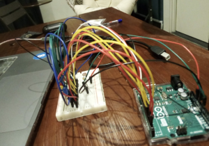
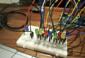
BREADBOARD & ARDUINO BOARD

HERE

DEMO

CODES

bool button = LOW; 
int light = 0; 

void setup() {
  // put your setup code here, to run once:
    pinMode(7, INPUT);
  for (int i = 2; i < 14; i++) {
    pinMode(i, OUTPUT);
  }
  Serial.begin(9600);
}

void loop() {
  // put your main code here, to run repeatedly:
  button = digitalRead(7);
  light = analogRead(A0);

  int mappedLight = map(light, 0, 1023, 0, 255);
  Serial.print("Analog value : ");
  Serial.print(light);
  Serial.print(" Mapped value : ");
  Serial.println(mappedLight);
  
  if (button == HIGH) {
    for (int i = 2; i < 7; i++) {
      digitalWrite (i, HIGH); //turns on red LED
      analogWrite(i, mappedLight);
    }
    for (int j = 8; j < 14; j++) {
      digitalWrite (j, LOW);        //turns off green LED
    }
  }
  else {
    for (int i = 2; i < 7; i++) {
      digitalWrite (i, LOW);        //turns off red LED
    }
    for (int j = 8; j < 14; j++) {
      digitalWrite (j, HIGH);        //turns on green LED
      analogWrite(j, mappedLight);
    }
  }
}

CHALLENGES

Given the fact that 10 LEDs were used, the breadboard obviously look messy, which made it hard to organize. It was not simple to figure out the mistake in the circuit, but, with patience, it came out alright.

Week 9: Give Some Space to Your Soft Toys Too!

This week we had to use both analog and digital input and connect them to LEDs to give analog and digital input. When professor mentioned soft toys in class, my mind went back to my own soft toy, a small cuddly raccoon. I thought about how most people hug their soft toys, but maybe when they are in distress they might forget how much force they are actually applying and end up hurting their soft toy by squeezing too hard.

So, my idea was to use a force sensor and attach it to a soft toy, and using the analog input, either a green, yellow or red LED will slowly light up using mapped values, depending on the force values (which go from around 0 to a 1000). The digital input would be a button which would switch on a blue LED to indicate you are using the set-up. Once the red LED lights up and there’s an overload, the blue light will start blinking to get your attention so that you can stop holding your soft toy so tight.

This project took me a lot of time to complete, because I couldn’t debug it properly before the submission day (I know, I know, I did it again) and then I spent the whole of next day and night sleeping after taking a painkiller after my Pfizer booster shot. Major major thanks to Eric, who helped me figure out today why it wasn’t working and finally get the outcome I wanted. It only took a few lines of code to be changed in the end, as is usually the (very frustrating) case in coding.

The first problem I had was that the analog input wasn’t working as it should, even though I reinitialised each LED every time in the loop. This was fixed by making a function for the default (LOW) states and calling them in each if block. And then, once analog was working, the digital part suddenly didn’t light up as brightly as before but I realised that was because I had forgotten to declare the pinMode for the blue LED in the mess of copy and pasting. Apart from that, digital output mostly involved Frankensteining different bits of code from class.

Here is the code, and the comments will hopefully make it clear:

const int force = A0;
const int led1 = 3;
const int led2 = 5;
const int led3 = 6;
const int led4 = 7;
const int button = 2;
unsigned long timer = 0;
int timerAmount = 100;
bool flip = false;
bool onOff = false;
bool prevButtonState = LOW;
bool overload = false;

void setup() {
  
  Serial.begin(9600);
  pinMode(led1, OUTPUT);
  pinMode(led2, OUTPUT);
  pinMode(led3, OUTPUT);
  pinMode(led4, OUTPUT);
  pinMode(button, INPUT);
  timer = millis();
}

void loop() {
  
  int mappedValue;
  int forceValue = analogRead(force);

  Serial.print("Force value: "); //for debugging
  Serial.println(forceValue);

  //green light
  if (forceValue <= 300) {
    off();
    mappedValue = map(forceValue, 0, 300, 0, 255);
    analogWrite(led3, mappedValue);
    overload = false;
  }

  //yellow light
  else if (forceValue <= 750) {
    off();
    mappedValue = map(forceValue, 301, 750, 0, 255);
    analogWrite(led2, mappedValue);
    overload = false;
  }

  //red light
  else if (forceValue <= 1100) {
    off();
    mappedValue = map(forceValue, 751, 1000, 0, 255);
    analogWrite(led1, mappedValue);
    overload = true;
  }

  //to switch on the blue light once
  bool currentState = digitalRead(button);
  if (currentState == HIGH &&  prevButtonState == LOW) {
    onOff = !onOff;
    digitalWrite(led4, onOff);
  }

  prevButtonState = currentState;

  //to make the blue light blink when there's an overload ie the red light is on
  if (overload == true) {
    if (onOff == true && millis() >= timer) {

      flip = !flip;
      digitalWrite(led4, flip);
      timer = millis() + timerAmount;

    }
    else if (currentState == LOW) {
      digitalWrite(led4, LOW);
    }
  }
}

//default state 
void off() {
  analogWrite(led1, LOW);
  analogWrite(led2, LOW);
  analogWrite(led3, LOW);
}

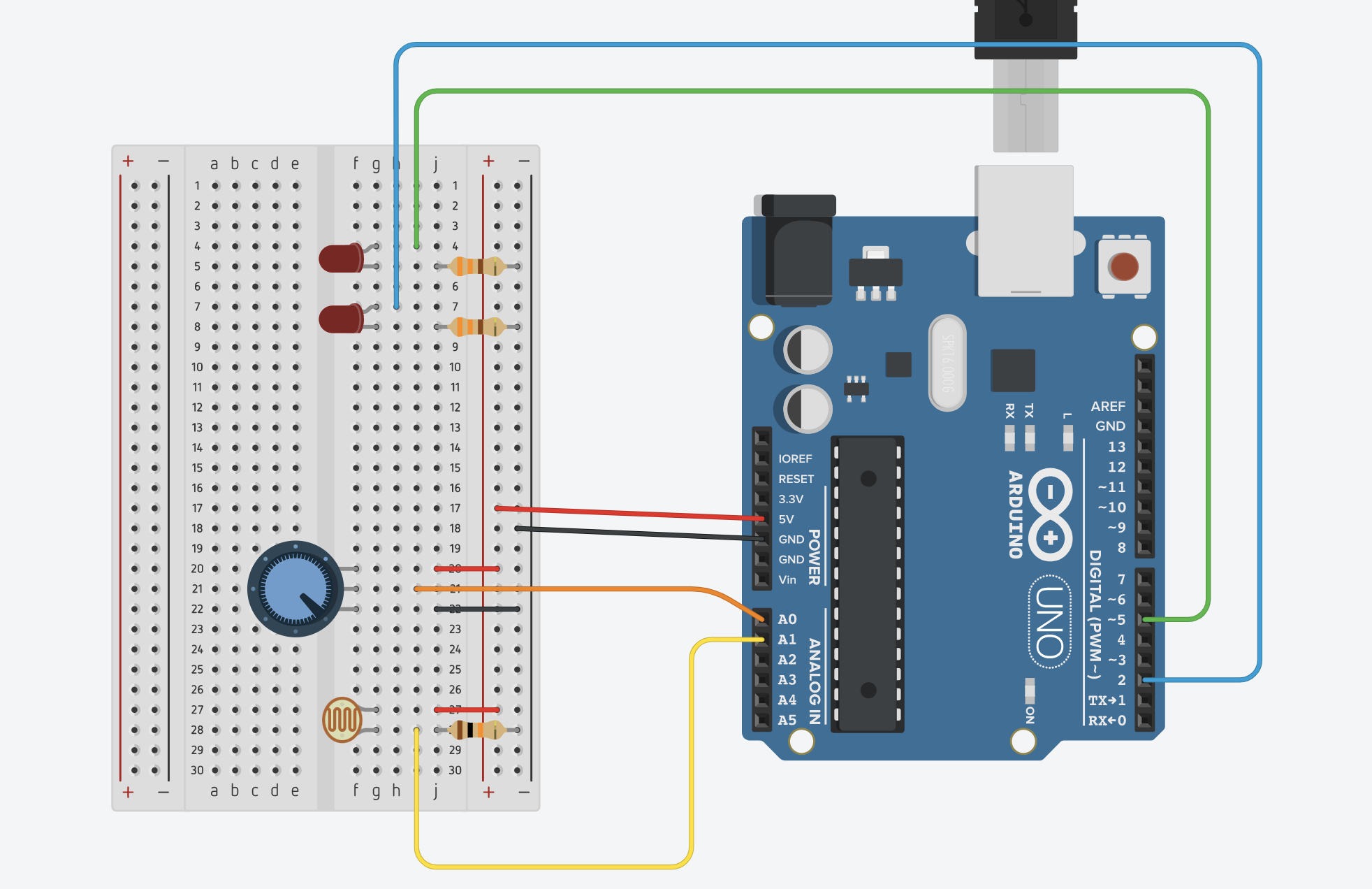
Here is how the circuit works:

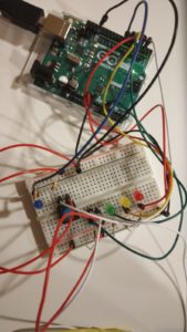
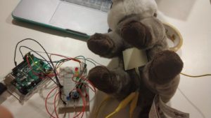
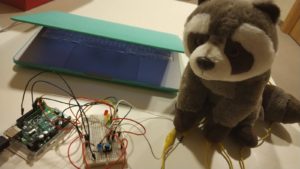
And here are some pictures of the circuit, along with how it looked after I attached it to my raccoon using tape:

And this is a final demonstration of how it is supposed to work:

I think that’s all, I can’t think of anything else to add here except for a thank you to Eric once again and apologies for the late post (once again)!

Emergency light

Main idea:

For this assignment, I tried to build an emergency light that automatically turns on whenever there is a power outage using both an analog sensor (LDR) and a digital sensor (switch).

Components:

x1 LDR

x1 Button push switch

x2 10K resistors

x1 350 resistor

x7 wires

View post on imgur.com

Process:

When the photoresistor’s surface (LDR) receives enough luminosity (light), its resistance decreases and is read by the program. When the values go lower than 350, it means that there was a power outage, therefore, the program turns the LED on. If the values remain higher than 350, the LED stays off and no power outage is detected.

Global variables:

I am using four global variables (3 are of data type int for the pins, and one boolean variable to check the state of the LED).

int led = 3; // LED pin 
int ldr = A0; // LDR pin 
int button = 5; // Button pin 
bool on = false; // Boolean variable for the state of the LED
Setup():

In the setup function, I mainly set the components to the pins (LED to 3, switch to 5, and LDR to A0) and set Serial.begin() to 9600.

void setup() { 
   Serial.begin(9600); 
   pinMode(led, OUTPUT); // Set the LED pinmode 
   pinMode(ldr, INPUT); // Set the LDR pinmode 
   pinMode(button, INPUT); // Set the button pinmode 
}
Loop():

To achieve the desired result, I am using analogRead() to get the luminosity’s value, then check if it is higher or lower than 350 using if/else conditions. 

// read the brightness from the ldr 
int brightness = analogRead(ldr);
// if its dark (power outage) 
if (brightness < 350) { 
   digitalWrite(led, HIGH); 
} 
// if everything is normal (light) 
else { 
   digitalWrite(led, LOW); 
}

The switch here works as an ON/OFF button for the whole process. I am using a boolean variable as well as digitalRead() to check the state of the LED.

// check if switch is clicked 
if (on == false && digitalRead(button)== HIGH){     
    on = true; 
} 
if (on == true && digitalRead(button) == HIGH){ 
   on = false; 
}

Challenges & thoughts:

To give it a realistic look, I wanted to add a delay() function after the click, and before the lights go on or off, but I wasn’t sure if it would affect the interactivity (mainly when the user clicks on the button). Therefore, I decided to avoid it.

Demo:

View post on imgur.com

Code:
int led = 3; // LED pin
int ldr = A0; // LDR pin
int button = 5; // Button pin
bool on = false; // Boolean variable for the state of the LED


void setup() {
  Serial.begin(9600);
  pinMode(led, OUTPUT); // Set the LED pinmode
  pinMode(ldr, INPUT); // Set the LDR pinmode
  pinMode(button, INPUT); // Set the button pinmode
}

void loop() {
// read the brightness from the ldr
  int brightness = analogRead(ldr);
// check if switch is clicked
  if (on == false && digitalRead(button)== HIGH){
    on = true;
  }
  if (on == true && digitalRead(button) == HIGH){
    on = false;
  }
  // if switch is clicked, then proceed 
  if (on==true){
// if its dark (power outage)
    if (brightness < 350) {
      digitalWrite(led, HIGH);
    }
// if everything is normal (light)
    else {
      digitalWrite(led, LOW);
    }
  }
  else if (on==false) {digitalWrite(led, LOW);}
}


Ford Cardboard Truck

Description:

Get information from at least one analog sensor and at least one digital sensor (switch), and use this information to control at least two LEDs, one in a digital fashion and the other in an analog fashion, in some creative way.

Process:

I first started this process, just by completing the circuit and finishing the requirements of the assignment, that is, to use a sensor (analog), button (digital switch )

I used 4 LEDs, 6 resistors ( 4 – 330 v and 2- 10k), jumper cables, LDR (Light-dependent resistor) resistors, breadboard, and Arduino board.

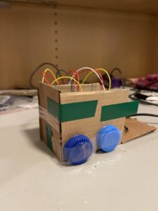
I used the LDR in a way in which if the surroundings are bright (more than 400 (LDR sensor status)), blue LED would light up, and if the surroundings are dark(less than 400 (LDR sensor status)), green LED would light up. By bending the lights a little and using the cardboard, I made it look like a car.

So, I used the LEDs as the front light of the truck. Then, I had to use a switch, so I did that by using the back of the truck.

So, if I closed the back of the truck, one red LED would light up, if I opened it, the other would light up.

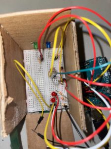
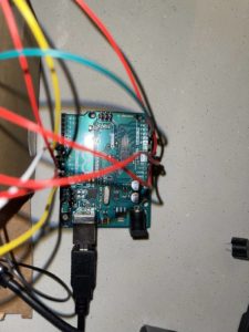
This is what the breadboard and Arduino looked like:

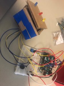
This is how the LDR resistor looked like when it worked:

Overall, it was fun to use my creativity to learn how to use these tools.

The code for this is given below:

const int ledPin = 10;
const int ledPin2 = 9;
const int knobPin = A1;

const int ledRed = 13;
const int switch1 = 7;
const int ledBlue = 12;
bool currentState = false;
bool switchState = LOW;


void setup() {
  // put your setup code here, to run once:
  Serial.begin(9600);
  pinMode(ledPin, OUTPUT);
  pinMode(ledPin2, OUTPUT);
  pinMode(knobPin, INPUT);

  pinMode(ledRed, OUTPUT);
  pinMode(ledBlue, OUTPUT);
  pinMode(switch1, INPUT);

}

void loop() {
  // put your main code here, to run repeatedly:

  int ldrStatus = analogRead(knobPin);

  if(ldrStatus <= 400){
    digitalWrite(ledPin, HIGH);
    digitalWrite(ledPin2, LOW);
    
    }
    else{
      digitalWrite(ledPin, LOW);
      digitalWrite(ledPin2, HIGH);
      
      
      }

    switchState = digitalRead(switch1);
    if (currentState != switchState ){
      digitalWrite(ledBlue, LOW);
      digitalWrite(ledRed, HIGH);
     } else {
      digitalWrite(ledBlue, HIGH);
      digitalWrite(ledRed, LOW);
    }
}


Week 9: Night Musical Box!

Description 

Get information from at least one analog sensor and at least one digital sensor (switch), and use this information to control at least two LEDs, one in a digital fashion and the other in an analog fashion, in some creative way.

Process

I started with creating a box out of the cardboard, with holes on the top for the lights. Using the light sensor , I detected when the lights were out and only when it was dark would the potentiometer (knob) get power from its port, and transfer it current to different leds and the buzzer. I used 330 ohm resistor for each leds, and 10k resistor for the light sensor and the buzzer.  Here is a photo of the setup:

The output of the knob is divided between three intervals. On each interval, one light lights up , starting with the yellow led and ending at the blue one.  The buzzer too at each interval beeps at different frequencies, giving a musical note.

Here’s a video:

CODE: 

//declaring the ports
const int pot_power = 2;
const int ledyellow = 3;
const int ledred = 5;
const int ledblue = 9;
const int buzzer = 11;
const int light = 13;
const int pot = A0;

void setup() {
  // put your setup code here, to run once:
  Serial.begin(9600); // begin detecting the sensors
  //declaring role of each port
  pinMode(pot_power, OUTPUT);
  pinMode(ledyellow, OUTPUT);
  pinMode(ledred, OUTPUT);
  pinMode(ledblue, OUTPUT);
  pinMode(buzzer, OUTPUT);
  pinMode(light, INPUT);
}

void loop() {
  // put your main code here, to run repeatedly:

  int lightValue = digitalRead(light); //reading value from the light port


  if (lightValue = 1) { //condition
    digitalWrite(pot_power, HIGH);
  } else {
    digitalWrite(pot_power, LOW);
    noTone(buzzer);// switch off buzzer
  }
  delay (100);

  int potValue = analogRead(pot); // reading value of the dial
  int mappedValue = map(potValue, 0, 1023, 0, 255); //mapping it to a value compatible for LEDs
  //  Serial.println(lightValue);
  //  Serial.println(mappedValue);
  //condition
  if ( mappedValue < 85) {
    analogWrite(ledyellow, HIGH);
    analogWrite(ledred, LOW);
    analogWrite(ledblue, LOW);
    tone(buzzer, 1000);
  }
  if (mappedValue >= 85 && mappedValue < 170) {
    analogWrite(ledyellow, LOW);
    analogWrite(ledred, HIGH);
    analogWrite(ledblue, LOW);
    tone (buzzer, 1500);
  }
  if (mappedValue >= 170) {
    analogWrite(ledyellow, LOW);
    analogWrite(ledred, LOW);
    analogWrite(ledblue, HIGH);
    tone(buzzer, 2000);
  }
  delay(100);
}


Night Light

Description

 Get information from at least one analog sensor and at least one digital sensor (switch), and use this information to control at least two LEDs, one in a digital fashion and the other is an analog fashion, in some creative way.

Inspiration

LEDs usually go with a college dorm. Two good things usually happen in a college dorm – a sound sleep or a loud party. I want to recreate these two scenarios using LEDs, an analog sensor, and a digital switch.

Process

From very well mind  ,the color blue is associated with the feeling of calmness or serenity. It is peaceful, tranquil, and secure which is great for sleep. Yet as a cool color, blue can sometimes seem icy, distant, or even cold. Hence can also lower the pulse rate and body temperature- the best conditions for sleep.

I didn’t have to do research for party LED, we can agree, we are going disco and loud.

This is how the setup is going to work. A dark room will stimulate the photosensor, turning on the blue led, it’s time to sleep. However, there is a button to switch to a party mode, with a lot of colorful lights.


Final Work


Challenges

I struggled for a long time in fixing the button to control the party LEDs. I tried different positions and connections on the breadboard to make it work. I tried to draw my circuit in an Arduino simulator Tinkercad but couldn’t get the hang of it. I had a lot of wires all over the breadboard, I needed a bigger breadboard.

Code
const int knob = A0;

//button
int buttonPin = 11;
bool onOff = false;
bool prevButtonState = LOW;

//sleep
const int led = 13;


//party
const int Led2=2;
const int Led3=3;
const int Led4=4;
const int Led5=5;
const int Led6=6;
const int Led7=7;
const int Led8=8;
const int Led9=9;


int i;
int c;


void setup() {
  Serial.begin(9600);
   
 pinMode(led, OUTPUT);
 pinMode(knob, INPUT);
 pinMode(buttonPin, INPUT);


  pinMode(Led2,OUTPUT);
  pinMode(Led3,OUTPUT);
  pinMode(Led4,OUTPUT);
  pinMode(Led5,OUTPUT);
  pinMode(Led6,OUTPUT);
  pinMode(Led7,OUTPUT);
  pinMode(Led8,OUTPUT);
  pinMode(Led9,OUTPUT);

}

void loop() {

   int knobValue = analogRead(knob);
  

 if (knobValue > 300){
    digitalWrite(led,HIGH);
  }
  

  else{
    digitalWrite(led,LOW);
    }

    
 bool currentState = digitalRead(buttonPin);
  
  if(currentState == HIGH && prevButtonState == LOW){
      onOff = !onOff;
      Serial.println(onOff);
      if (onOff == true){
        digitalWrite(led,LOW);
        party();
       }

       else{
        noParty();
        }
    }

      prevButtonState = currentState;
  
}

void party(){
  
  
for(i=1;i< 100;i++)
  {
    if(i%2==0)
    {
       digitalWrite(Led2,HIGH);
       digitalWrite(Led4,HIGH);
       digitalWrite(Led6,HIGH);
       digitalWrite(Led8,HIGH);
       digitalWrite(Led3,LOW);
       digitalWrite(Led5,LOW);
       digitalWrite(Led7,LOW);
       digitalWrite(Led9,LOW);
       wait(100);
      
    }
    else
    {
      digitalWrite(Led3,HIGH);
      digitalWrite(Led5,HIGH);
      digitalWrite(Led7,HIGH);
      digitalWrite(Led9,HIGH);
      digitalWrite(Led2,LOW);
      digitalWrite(Led4,LOW);
      digitalWrite(Led6,LOW);
      digitalWrite(Led8,LOW);
      wait(100);
     
    }
  }
  for(i=0;i<100;i++)
    {
      for(c=2;c<=i/2;c++)
      {
        if(i%c==0)
        {
          digitalWrite(Led2,HIGH);
          digitalWrite(Led4,HIGH);
          digitalWrite(Led6,HIGH);
          digitalWrite(Led8,HIGH);
          digitalWrite(Led3,LOW);
          digitalWrite(Led5,LOW);
          digitalWrite(Led7,LOW);
          digitalWrite(Led9,LOW);
          wait((i*10));
         
        }
      }
      if(c>i/2)
      {
        digitalWrite(Led3,HIGH);
        digitalWrite(Led5,HIGH);
        digitalWrite(Led7,HIGH);
        digitalWrite(Led9,HIGH);
        digitalWrite(Led2,LOW);
        digitalWrite(Led4,LOW);
        digitalWrite(Led6,LOW);
        digitalWrite(Led8,LOW);
        wait((i*10));
      }
    }
  
  
  }


  void noParty(){
     digitalWrite(Led2,LOW);
       digitalWrite(Led4,LOW);
       digitalWrite(Led6,LOW);
       digitalWrite(Led8,LOW);
       digitalWrite(Led3,LOW);
       digitalWrite(Led5,LOW);
       digitalWrite(Led7,LOW);
       digitalWrite(Led9,LOW);
    
    
    }

void wait(int period){
   long time_now = millis();
    while(millis() < time_now + period){
        //wait
    }
  
}


Analog and Digital LEDs

Inspiration:

I struggled to think of something creative to make, but I eventually settled on a kind of game where a red, a green, and a blue LED would light up, each with a random brightness, and then the player would have to use a potentiometer to control the brightnesses of each of the three LEDs in order to match the random brightness that they had. If the player was within a certain range, a green LED would light up, signifying that the player was correct, otherwise a red LED would light up signifying that the player was too far off.

Process:

I used some of the code from the Maintain State circuit we built, along with some from the Analog LED circuit from class as well.

Challenges:

My idea was quite complicated, especially for someone new at coding like me, and I spent too long trying to work it out. I eventually realized that I could have the same process with a blue LED that the player would control, which would make the circuit much simpler. I simplified my code and rebuilt my circuit, although for some reason, I encountered the same problem I had before, which was that all three LEDs would light up, and neither the button nor the potentiometer would change that.

I tinkered a little more, and the video shows as far as I got, however because I spent so much time on the more complicated version of this idea, I did not have enough time to completely troubleshoot either the code or the circuit. I had initially thought for a long time that the problem must have been somewhere in the code, but I think now that it might be in the circuit.

Final Work:

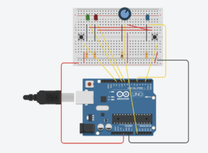
Diagram of my circuit on TinkerCAD

Code:

//potentiometer
const int knob = A0;
//target blue LED
const int bled = 5;
//incorrect and correct LEDs
const int iled = 9;
const int cled = 10;
//blue button
const int bbutton = 2;
//on/off button
const int obutton = 12;

bool bledOn = false;
bool iledOn = false;
bool cledOn = false;

//on off button
bool oButtonOnOff = false;
bool oButtonPrevOnOff = LOW;

//blue button
bool bButtonOnOff = false;
bool bButtonPrevOnOff = LOW;

void setup() {
  // put your setup code here, to run once:

  Serial.begin(9600);
  pinMode(bled, OUTPUT);
  pinMode(iled, OUTPUT);
  pinMode(cled, OUTPUT);
  pinMode(bbutton, INPUT);
  pinMode(obutton, INPUT);

}

void loop() {
//turning the LED on and off with the BLACK button
  bool oButtonCurrentState = digitalRead(obutton);
  int randomLED = random(255);
  if(oButtonCurrentState == HIGH && oButtonCurrentState != oButtonPrevOnOff){
    digitalWrite(bled, randomLED);
  }
  oButtonPrevOnOff = oButtonCurrentState;
  bledOn = !bledOn;

//turning the LED on and off with the BLUE button
  bool bButtonCurrentState = digitalRead(bbutton);
  if(bButtonCurrentState == HIGH && bButtonCurrentState != bButtonPrevOnOff){
    digitalWrite(bled, 255);
  }
  bButtonPrevOnOff = bButtonCurrentState;
  bledOn = true;
  
  int knobValue = analogRead(knob);
  //fix high and low based on potentiometer
  int mappedValue = map(knobValue, 850, 350, 0, 255);
  int constrainedValue = constrain(mappedValue, 0, 255);

  digitalRead(bled);
  if(bled == HIGH && bButtonPrevOnOff == HIGH){
    analogRead(knob);
    analogWrite(bled, constrainedValue);
  }

  int bledValue = analogRead(bled);
  if(bButtonCurrentState == HIGH &&  (randomLED - 5) < (bledValue) < (randomLED + 5)){
    bool cledOn = !cledOn;
  }
  if(bButtonCurrentState == LOW &&  (bledValue) < (randomLED - 5) || (randomLED + 5) < (bledValue)){
    iledOn = !iledOn;
  }
}


Squid Game

Introduction

Our task in this report is to get information from at least one analog sensor and at least one digital sensor (switch), and use this information to control at least two LEDs, one in a digital fashion and the other in an analog fashion, in some creative way.

I will use the Arduino prototyping board for the digital and analog input and output for the interaction.

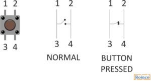
For the digital input I will use a push button.

For the digital output a LED is used.

For the analog input a sound sensor is used.

For the analog LED output an RGB LED is used.

Challenged Faced

The first challenge faced is to identify the needed input and output devices.

After researching the available simple devices, I decided on using buttons, sound sensor, LED and RGB LED.

The pins used for digital are the integer pins in the Arduino. The analog pins are pin A0 to A5 on the Arduino.

The second challenge was to do the circuit and connection required. I used tutorials from Arduino forums in order to connect the circuit.

The third challenge was to code the Arduino , using the Arduino IDE I wrote a code in C to program the Arduino.

Video:

Procedure

Step 1 : Button with LED output

Digital input controlling a digital input button.

Connecting the button:

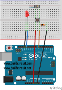
The button is connected to pin 7 through a resistor of 1 kohm.

Step 2 : LED Digital

The connection of the LED is to the digital pin 13.

Code for connecting the button and the led:

int ledPin = 13; // The LED is connected to pin 13
int button = 7; // The button is connected to pin 7
int val = 0;
void setup () {
   pinMode (ledPin, OUTPUT); // The LED pin is an output
   pinMode (button, INPUT); // The pin of the button is an entry
   }
void loop () {
 
   val = digitalRead (button); // Reading the button

   if (val == 1) {// If the value of the button is 1
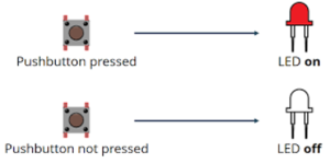
     digitalWrite (ledPin, HIGH); // Turn on the LED
   }
   else {// Otherwise:
     digitalWrite (ledPin, LOW); // Turn off the LED
   }
}

Step 3 : Input analog

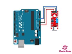
The analog input I are using is a sound sensor KY-037

It is connected to A0 analog pin on Arduino.

Step 4: Analog output

As analog output I will use the 4 pin RGB LED.

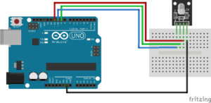
In order to make it easier to connect it, I will use a module of RGB light: KY-016 RGB FULL COLOR LED MODULE.

The module is an RGB 4 pin LED connected to 3 resistor each of 150ohm to protect the pins.

This module uses PWM in order to send analog signals to the LED to turn on in different colors.

The connection is done as per the table below:

Pins Arduino Pin
R Pin 11
B Pin 10
G Pin 9
GND GND

The code to control the RGB light is first to write in the setup:

pinMode(redpin, OUTPUT);
  pinMode(bluepin, OUTPUT);
  pinMode(greenpin, OUTPUT);
  Serial.begin(9600);

Then I need to add in the function setcolor:

void setColor(int red, int green, int blue)
{
  //use PWM to controlt the brightness of the RGB LED
  analogWrite(redPin, red);
  analogWrite(greenPin, green);
  analogWrite(bluePin, blue);
}

Now I can use the setcolor function in the Arduino loop code to change the color depending on different functions.

I programmed it depending on the sound of the sensor:

sound lower than 25 : no color

sound between 25 and 30 : yellow color

sound higher than 30 : red color

Using the code for colors:

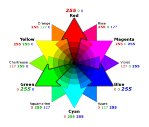
setColor(255, 0, 0);  // red
setColor(0, 255, 0);  // green  
setColor(255, 255, 0);  // yellow

Final Outcome:

The circuit is built now and all inputs and outputs are working.

In order to give it a mission, I designed the code as the following:

SQUID GAME green and red light

Rule of the game: the player should press the button when the red light is on

Winner: blue lights turns on

When squid game starts, the sound sensor detects it and start a sequence:

-Green light is on

-Green is off and Red light is on for a short time: in this time the player should press the button

-if the player pressed the button while the red light was on, he will win

-if the player wins both lights will be blue indicating a win

-if the player doesn’t press in time, no blue light is on, so he lost.

Rule of the game: the player should press the button when the red light is on

Winner: blue lights turns on

Song for quid game: https://www.youtube.com/watch?v=9jcHItQvKIQ

Conclusion

As I completed this project I learned about different inputs and outputs and how the Arduino could be used to have different applications.

Squid Game Code

int ledPin = 13; // The LED is connected to pin 13
int button = 7; // The button is connected to pin 7
int val = 0;
int redpin =11;
int bluepin=10;
int greenpin=9;

void setup () {
   pinMode (ledPin, OUTPUT); // The LED pin is an output
   pinMode (button, INPUT); // The pin of the button is an entry
   pinMode(redpin, OUTPUT);
  pinMode(bluepin, OUTPUT);
  pinMode(greenpin, OUTPUT);
  Serial.begin(9600);
setColor(0, 0, 0);
   }
void loop () {

   int sound = analogRead(A0); 

Serial.print(sound); Serial.println(" Sound"); 

//if (sound<40) setColor(, 0, 0);//green
//else if (sound<42) setColor(255, 255, 0);  //yellow
//else if (sound>42) setColor(255, 0, 0);  //red
if (sound>42)
{ setColor(255, 255, 0); 
delay(5000);
setColor(255, 0, 0);
delay(2000);
val = digitalRead (button); // Reading the button

   if (val == 1) {// If the value of the button is 1
     digitalWrite (ledPin, HIGH); // Turn on the LED
     setColor(0, 0, 255);
     delay(2000);
     digitalWrite (ledPin, LOW);
   }
   else {// Otherwise:
     digitalWrite (ledPin, LOW); // Turn off the LED
     delay(2000);
   }}

else setColor(0, 0, 0);

}
void setColor(int red, int green, int blue)
{
  //use PWM to controlt the brightness of the RGB LED
  analogWrite(redpin, red);
  analogWrite(greenpin, green);
  analogWrite(bluepin, blue);
}

Guess Who? : Analog and Digital LEDs

For this week’s assignment, I struggled a lot to come up with an idea, because I’ve never really had to think creatively in this medium (this case, arduino and LEDs), so it took a lot of brainstorming to conclude on an idea. I finally settled on a guessing game. It is a game you play wherein the code chooses a random bulb on the board, and you, as a player, have to guess which bulb it is. If you guess right, you win!

I used a potentiometer to get the analog input and a push-button for the digital input. I settled on five blue LEDs in total and the player has to guess which LED is the secret LED. There are green and red LEDs on the board that will indicate whether the chosen LED is correct. The choice is decided by rotating the knob on the potentiometer. And the choice is finally sealed in by pressing the push button.

Also, I wanted to put in some breather time in between two games and also when the game begins. I really liked the idea of showing patterns through LEDs, so I decided to make a pattern through the blue LEDs at the beginning of the game to settle in, and between games when whether the player is right or wrong is indicated.

Making the circuit was easier than I had anticipated. I imagined the absolute worst scenarios when I decided on the idea, but it helped me seal the concepts learned in class, so it went along better than expected 🙂

One problem I faced was the placement of the different elements on the board because at first I put in all the elements on one end of the board and it became very crowded, so I changed the placement and put in the potentiometer in the middle. While it can be troublesome to move in between the wires, it is intuitive in relation to the 5 LEDs surrounding it because the mapping is quite obvious. 

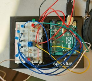
Here’s the circuit:

For the code itself, I divided the game into 4 different parts and worked on them one at a time, tested it, and then integrated it with whatever I had done until before and tested again.

The parts where:

    1. the patterns by the 5 blue LEDs
    2. potentiometer mapping to the 5 LEDs
    3. sealing the deal with the switch and checking whether the guess was right (and lighting the corresponding LED)
    4. Resetting the game to restart

Serial.print helped a lot with error correction. I had some trouble with the pushbutton and the resetting of the game. So, in addition to setting the numbers for mapping the knob value to the corresponding LED, the logs helped with the switch error too. The error I had was related to delays in the pattern function. While the pattern was still going on, the checking for the next guess would proceed, and this would cause the green/red bulb to light again. But this was a premature checking step as the player hadn’t chosen their next guess yet. So, I changed the code to make sure that all the variables were reset as soon as the push button was pressed and the pattern was called at the end of the game rather than executing the loop I had for the pattern at the beginning of the game (since it was too late by then). This solved all problems. 

Something I hadn’t realized before was that with analog input, I could also use the same for digital input too. While we did learn this in class, it hadn’t properly set in my mind until I did that with the code. I used digitalWrite for the 5 LED bulbs with the patterns in the beginning and analogWrite for the same bulbs when guessing the number. 

Here’s a demo:

Here’s the code: 

const int lightVis = 75;
const int num = 7;
int lightPins[7] = {2,3,4,5,6,10,11};
const int switchPin = 8;
const int knob = A0;
bool startPat = false; 
int pins[5]={1,3,4,5,6};
int randNumber = pins[random(5)]; 
bool gameOver = false;
bool prevButtonState = false;


void setup() {
  Serial.begin(9600); 
  for(int i=0;i<num;i++)
  {
    pinMode(lightPins[i],OUTPUT);
  }
  pinMode(switchPin,INPUT);
}


void loop() {
  bool currentState = digitalRead(switchPin);

  //pattern
  if( startPat == false){
  for(int i=0; i<=5; i++) {
     pattern();
     startPat = true;
  }
  }

  //green and red lights are now OFF
  digitalWrite(lightPins[2], LOW);
  digitalWrite(lightPins[0], LOW);

 //mapping knob values to corresponding LED 
  int knobValue = analogRead(knob);
  int ledNum;
  if ((knobValue>0 && knobValue<435) || knobValue<0)
    ledNum=6;
  if (knobValue>435 && knobValue<700)
    ledNum=5;
  if (knobValue>700 && knobValue<755)
    ledNum=4;
  if (knobValue>755 && knobValue<838)
    ledNum=3;
  if (knobValue>838)
    ledNum=1;
  
  
  Serial.print("Random Value: ");
  Serial.print(randNumber);
  Serial.print(" Knob Value: ");
  Serial.print(knobValue);
  Serial.print(" Mapped Value:");
  Serial.print(mappedValue);
  Serial.print(" ");
  Serial.print(currentState);
  Serial.print(" ");
  Serial.println(prevButtonState);

  analogWrite(lightPins[ledNum],254);
  for(int i=0; i<num; i++) {
     if(i!=ledNum){
        analogWrite(lightPins[i],0);
     }
  }


  if (currentState != prevButtonState && currentState==HIGH) {
    gameOver=true;
    if(ledNum==randNumber){
      digitalWrite(lightPins[0], HIGH);
      digitalWrite(lightPins[2], LOW);
    }
    else{
      digitalWrite(lightPins[2], HIGH);
      digitalWrite(lightPins[0], LOW);

    }
    prevButtonState = false;
    currentState=false;
  }


  if(gameOver)
  { 
    
    randNumber = pins[random(5)]; 
    gameOver = false;
    for(int i=0; i<=5; i++) {
     pattern();
    
  }
     
  }
  
}


void pattern(){ 
    for(int i=0; i<num; i++) {
      if(lightPins[i]!=2 && lightPins[i]!=4)
      {
        digitalWrite(lightPins[i],HIGH);
        delay(lightVis);
        digitalWrite(lightPins[i],LOW);
      }
 
    }
    
    for(int i=num-1; i>=0; i--) {
      if(lightPins[i]!=2 && lightPins[i]!=4)
      {
        digitalWrite(lightPins[i],HIGH);
        delay(lightVis);
        digitalWrite(lightPins[i],LOW);
      }
    }
}   

This will be a fun replacement for heads or tails. I’ve used heads/tails toss to make a lot of arbitrary decisions before, but I’m thinking that in situations wherein I’m leaning against a particular choice, this would be a great way to make a decision as there’s only a 1/5th chance of getting it right! But if you do guess right, even probability isn’t on your side ://

References:

https://create.arduino.cc/projecthub/thingerbits/9-led-patterns-with-arduino-277bf1