“Please Don’t Laugh When I Am Sleeping”

INSPIRATION

My suitemates would bring friends over to “study” at 3 AM. They would laugh, play music, and shout all the way to 5 AM when my roommate and I had 9 AM classes the next day. Therefore, I am creating an indicator that there is someone asleep in the room and the wall is paper-thin, even though they probably know that but chose to ignore the fact. Anyways, if this subtle hint doesn’t work, I will do something else.

IDEA

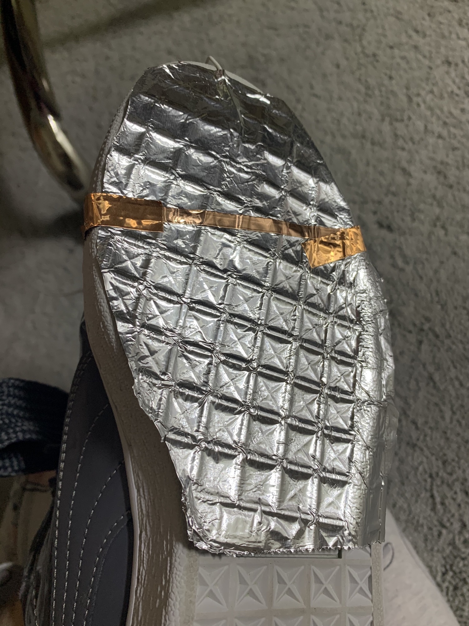
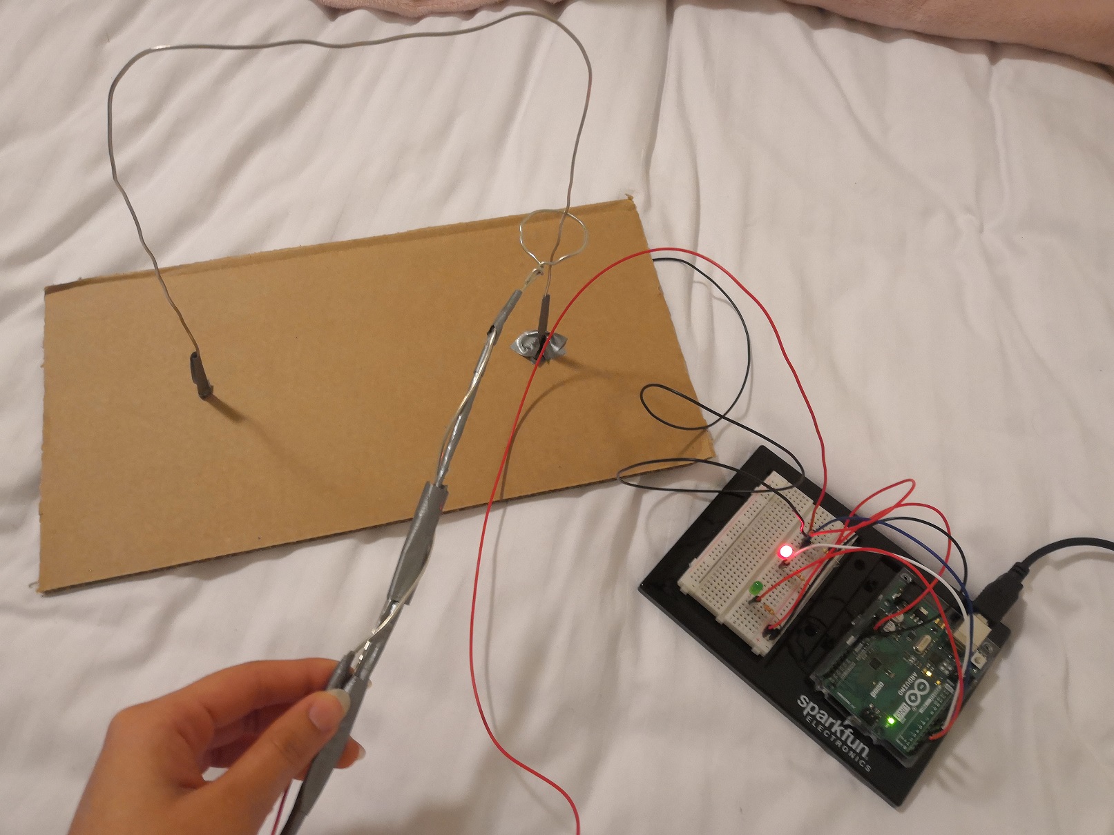
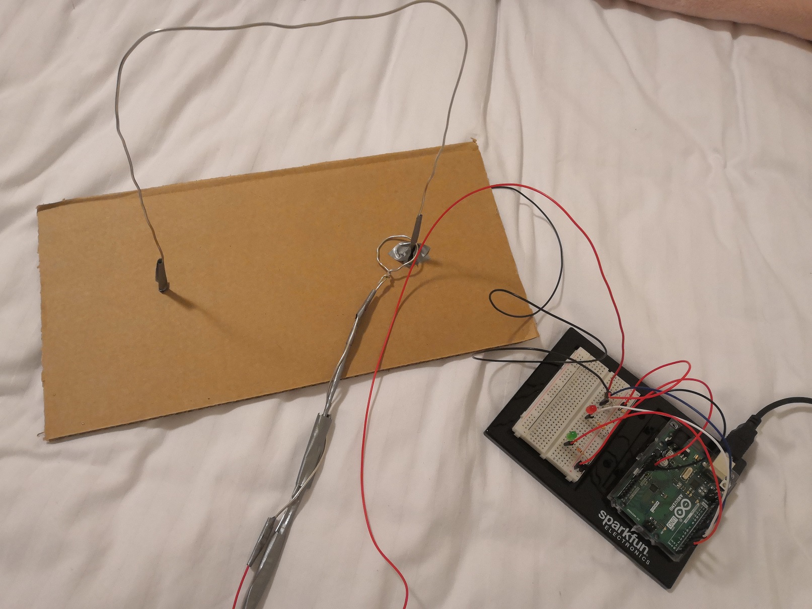
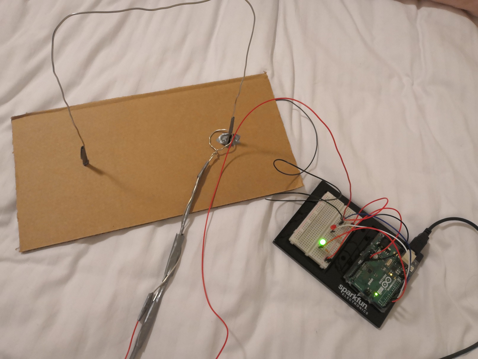
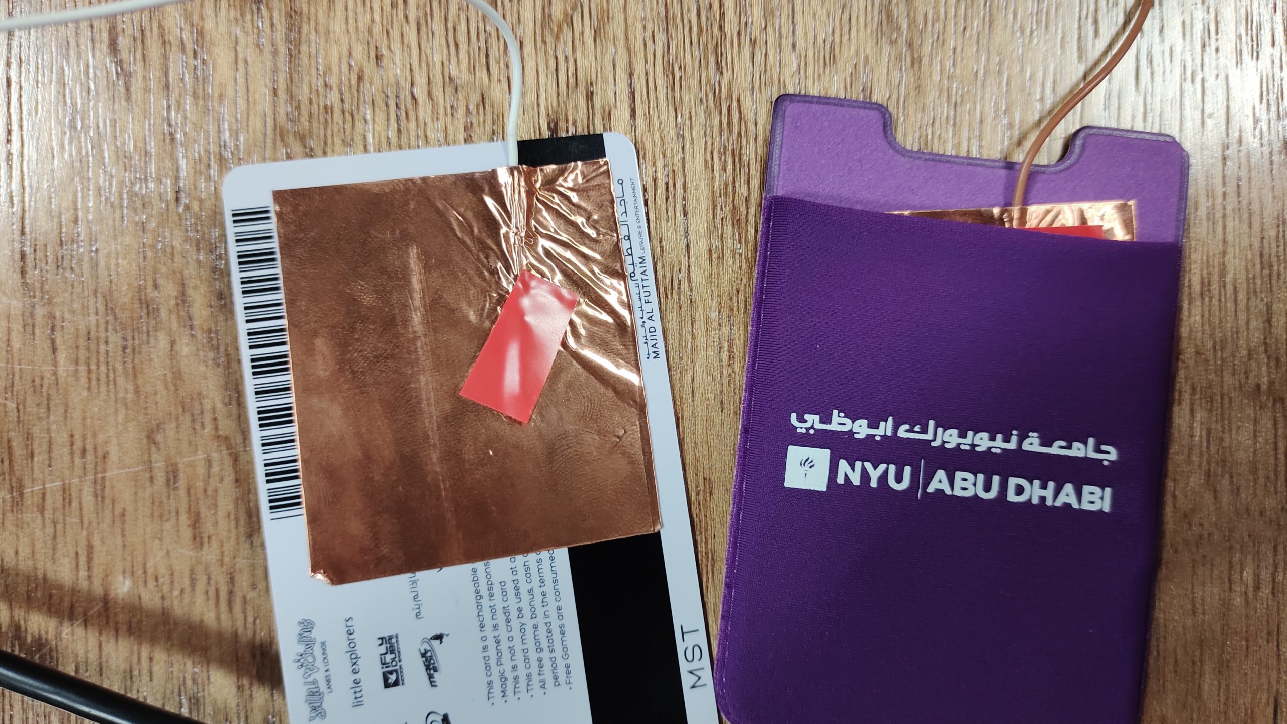
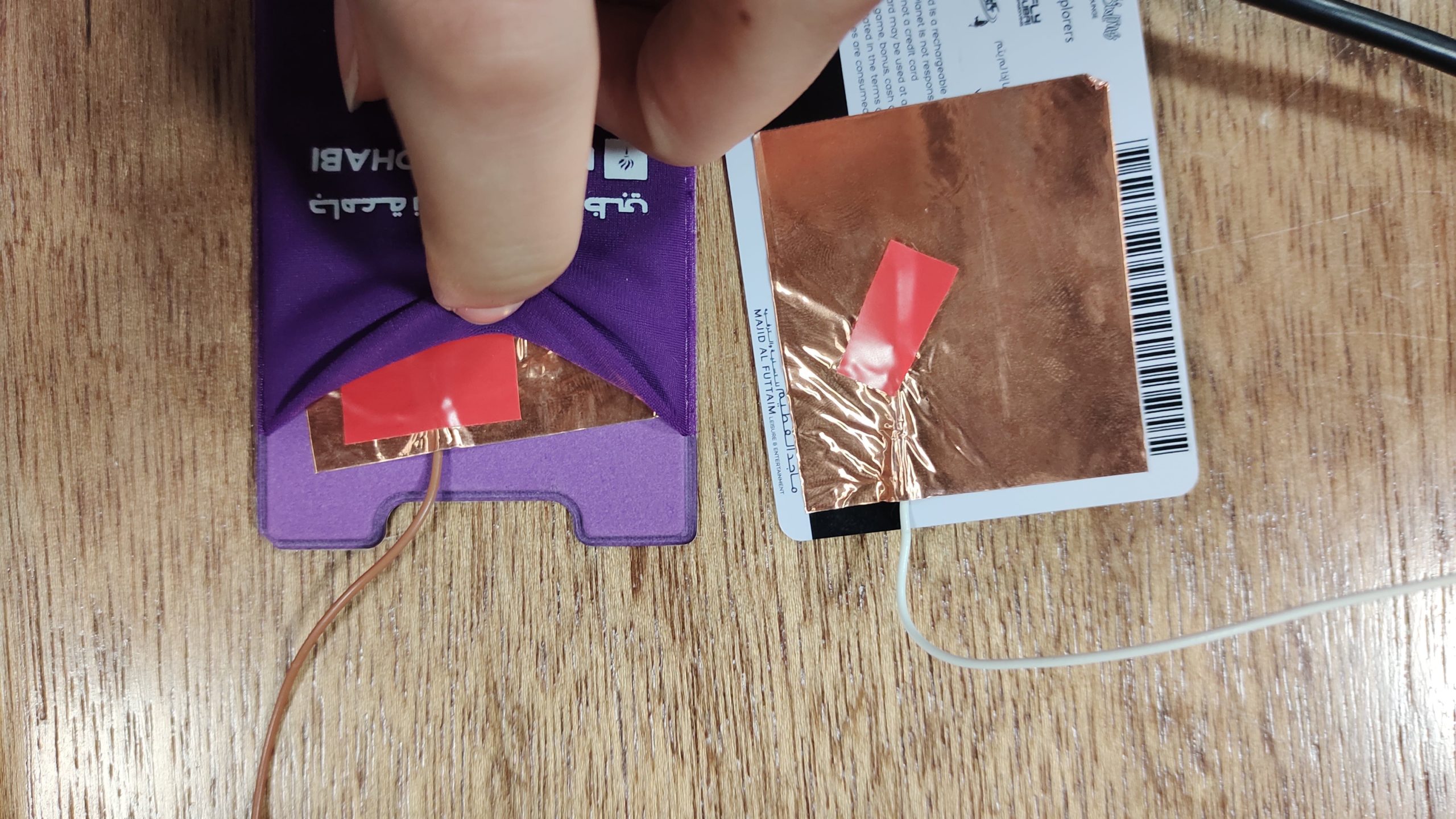
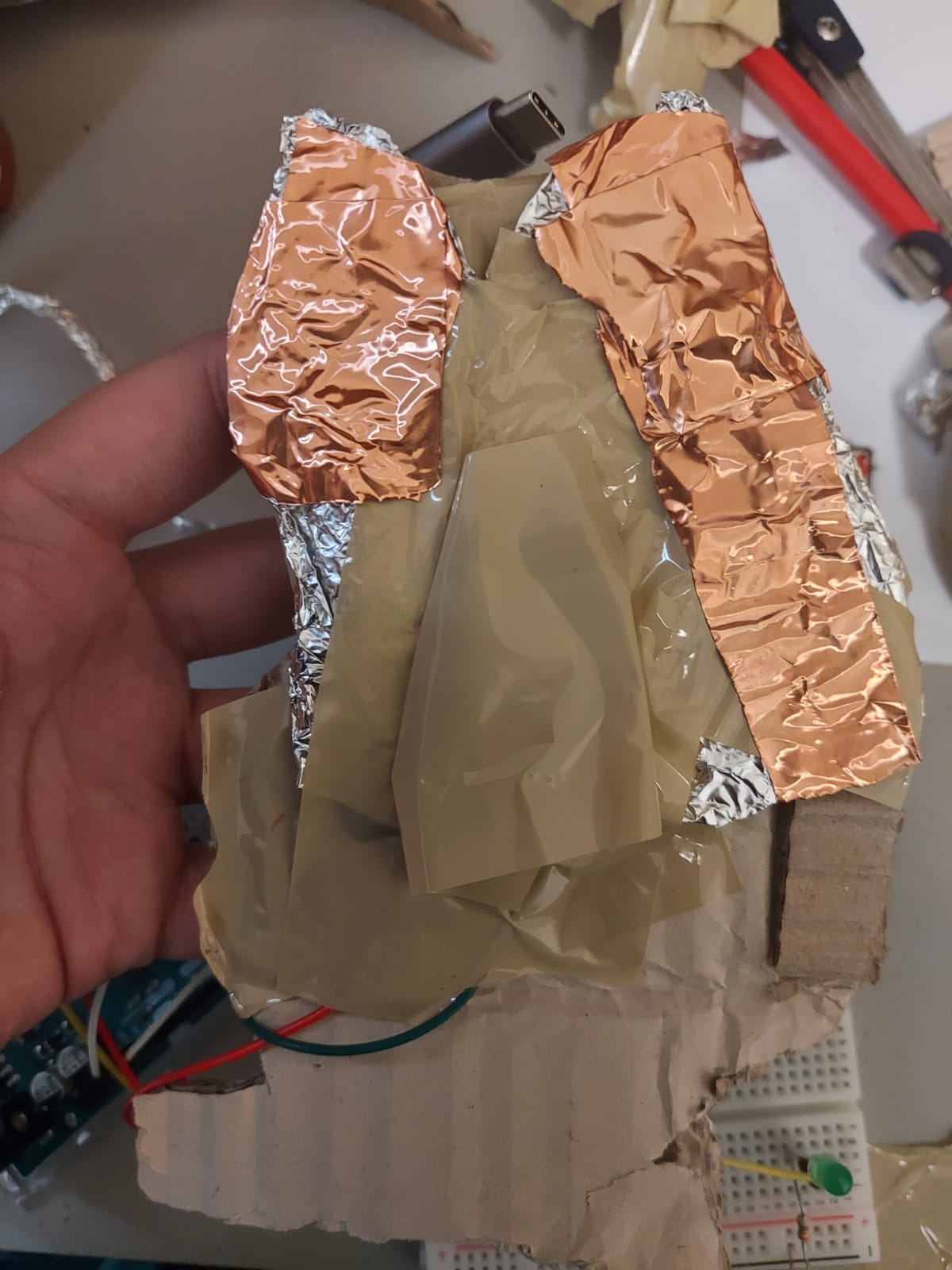
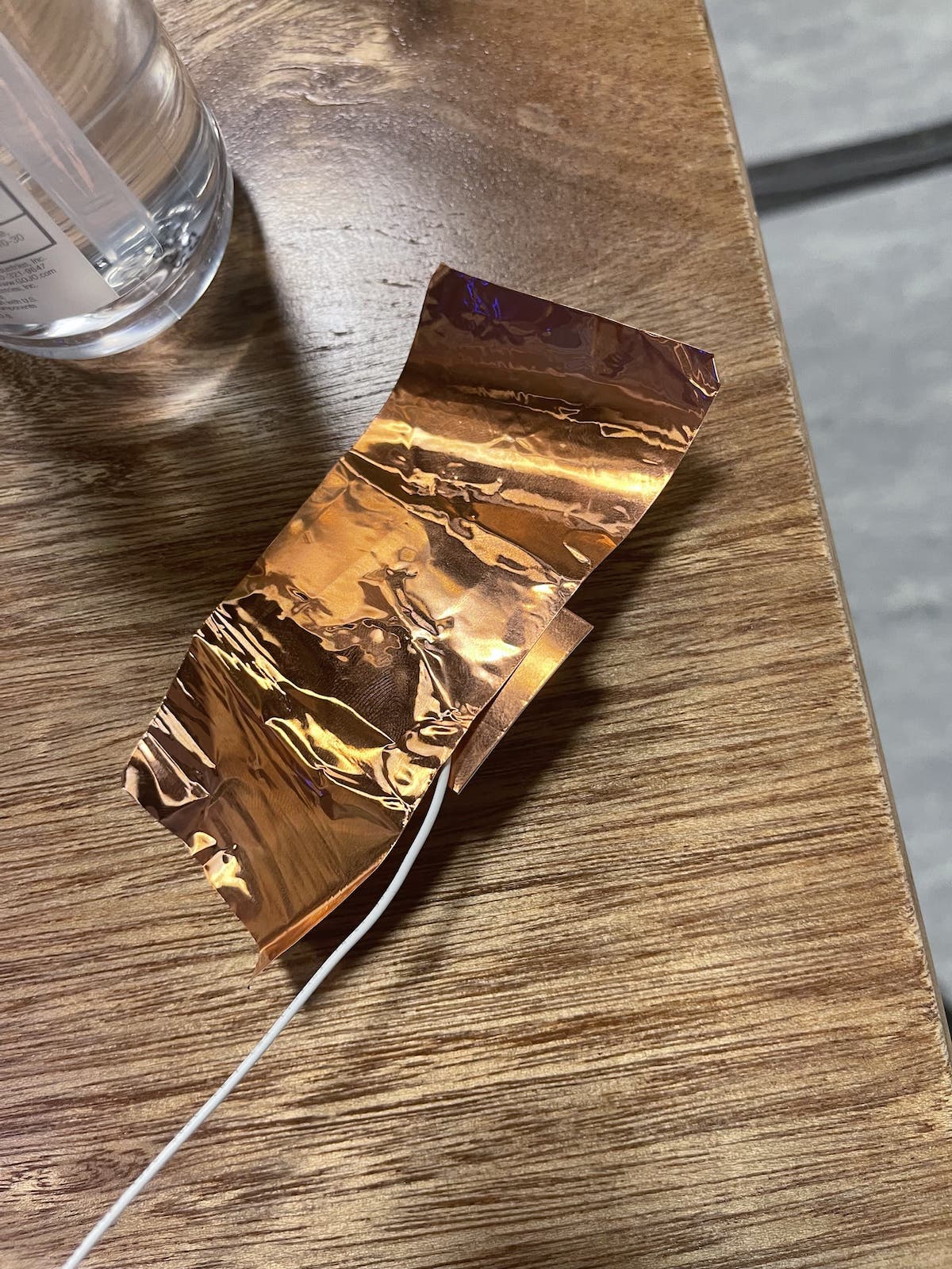
When the two aluminum foil touch, the boolean turns true, and green turns off and red turns on. On the other hand, when they part, the boolean turns false, and green turns on and red turns off.

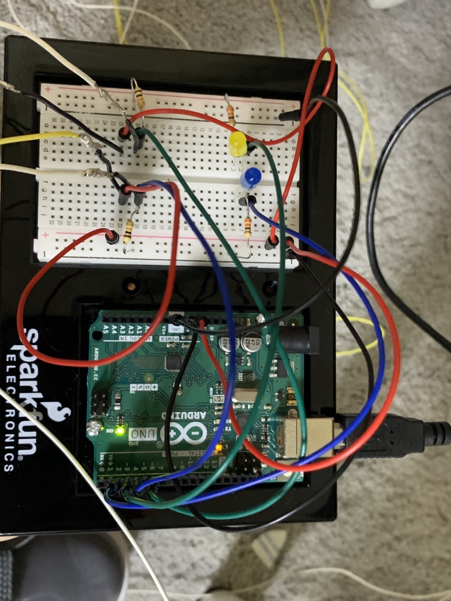
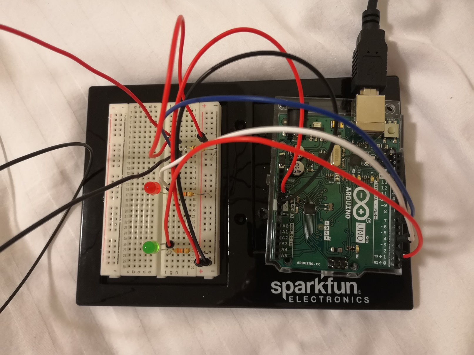
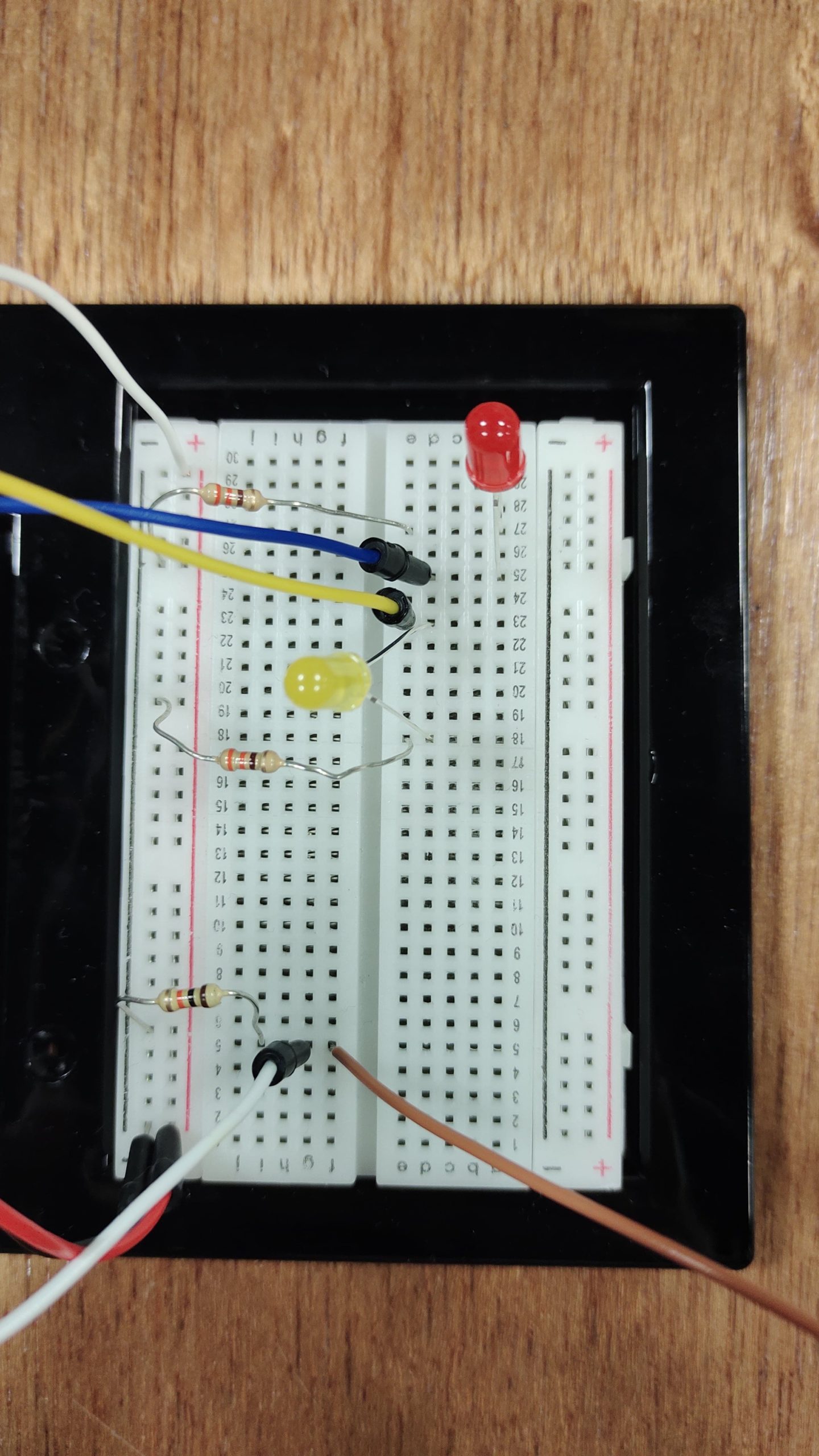
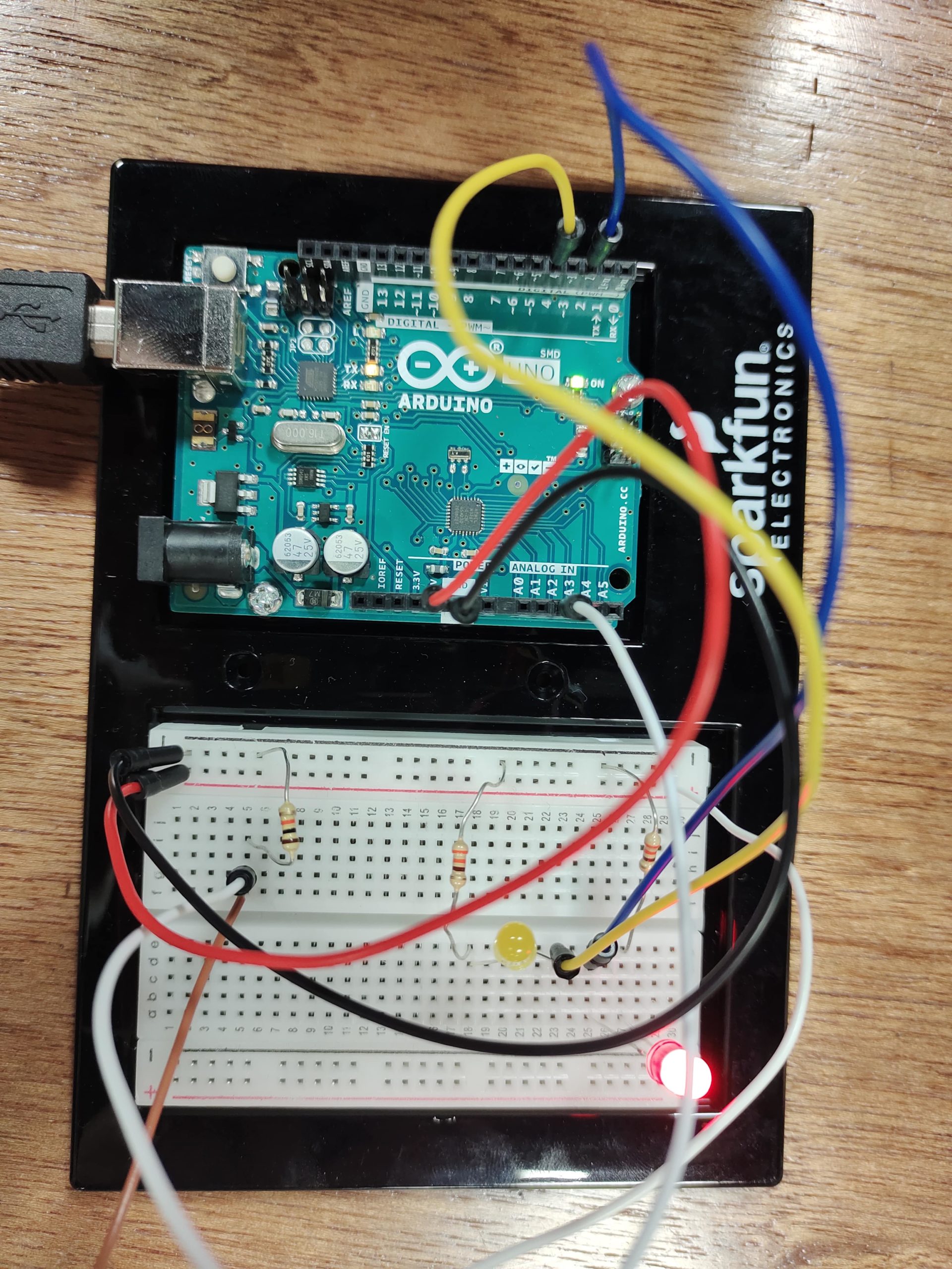
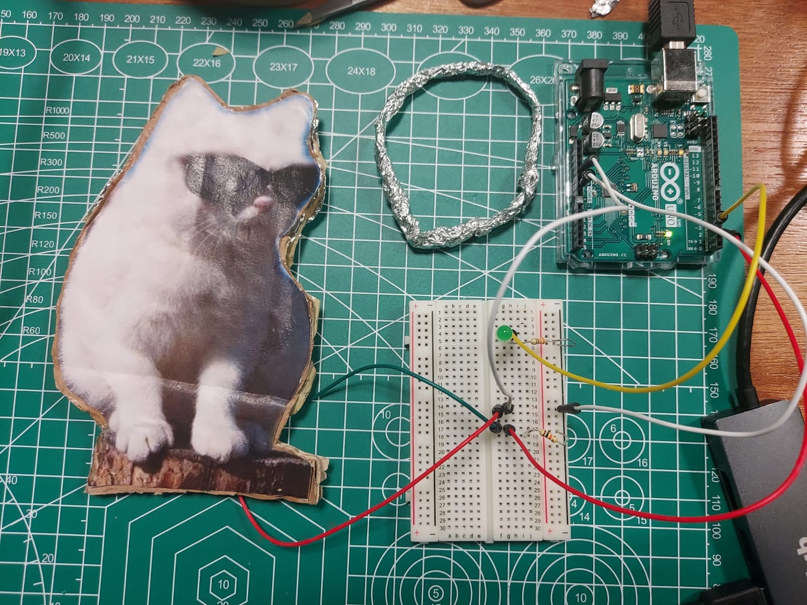
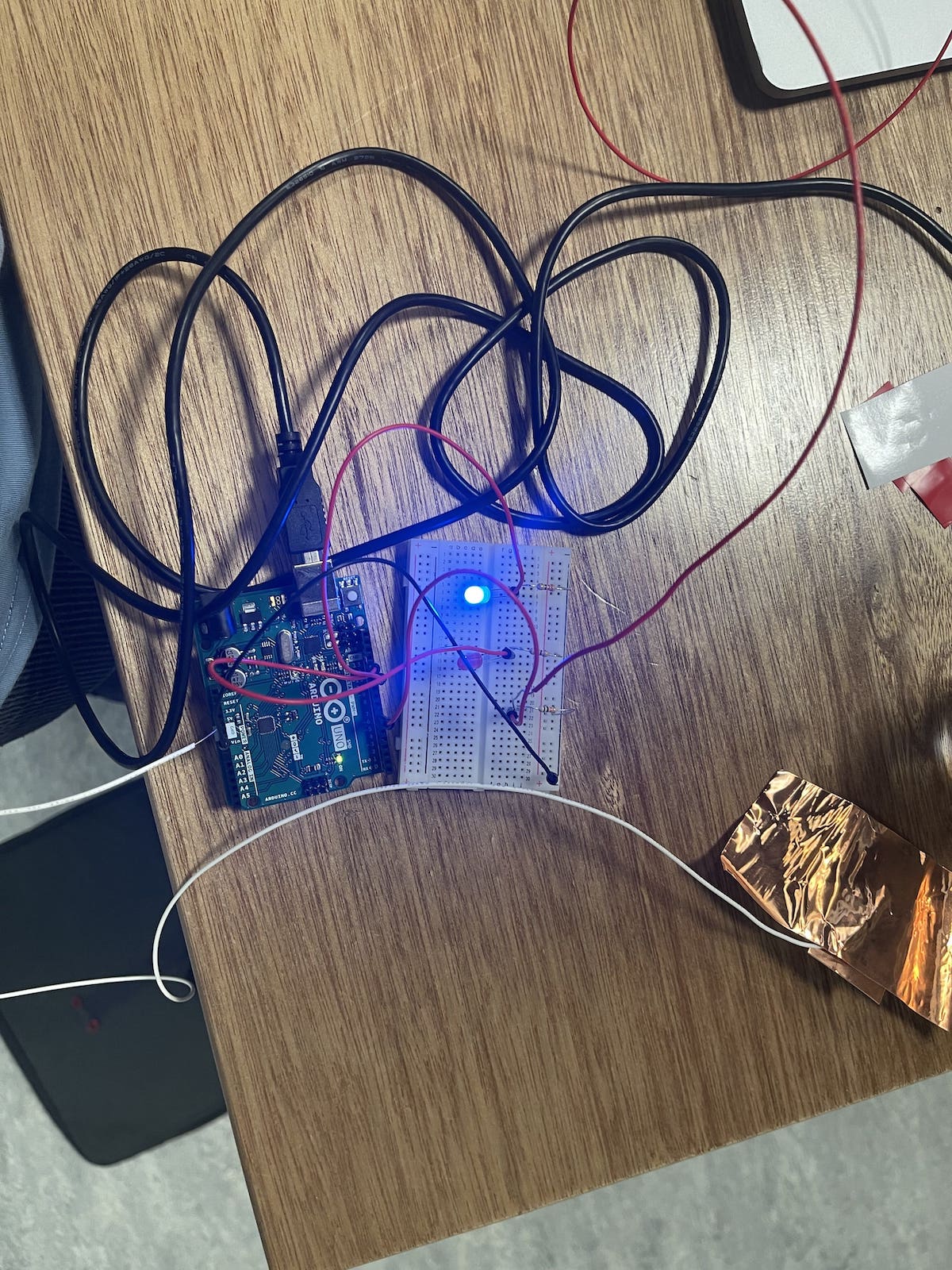
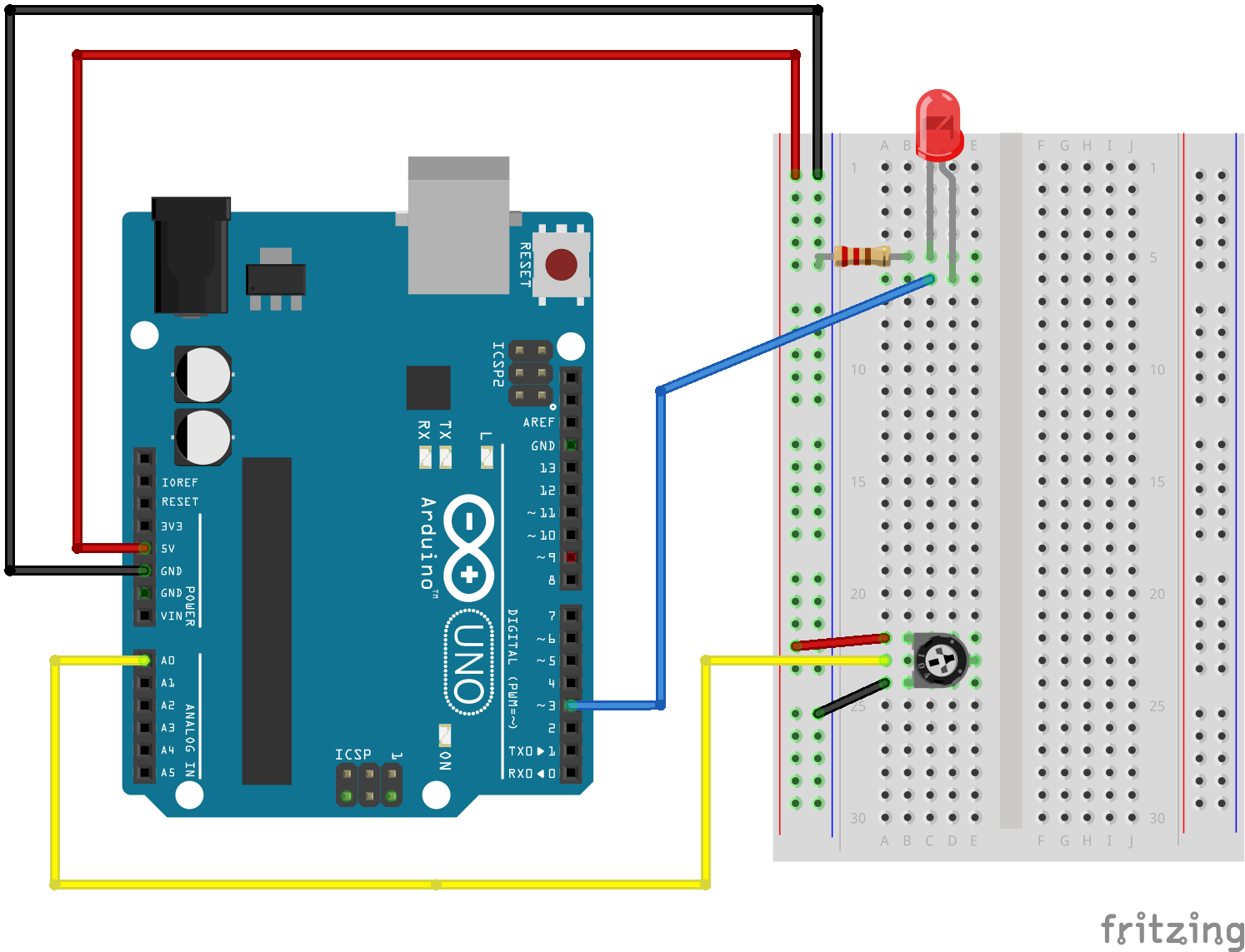
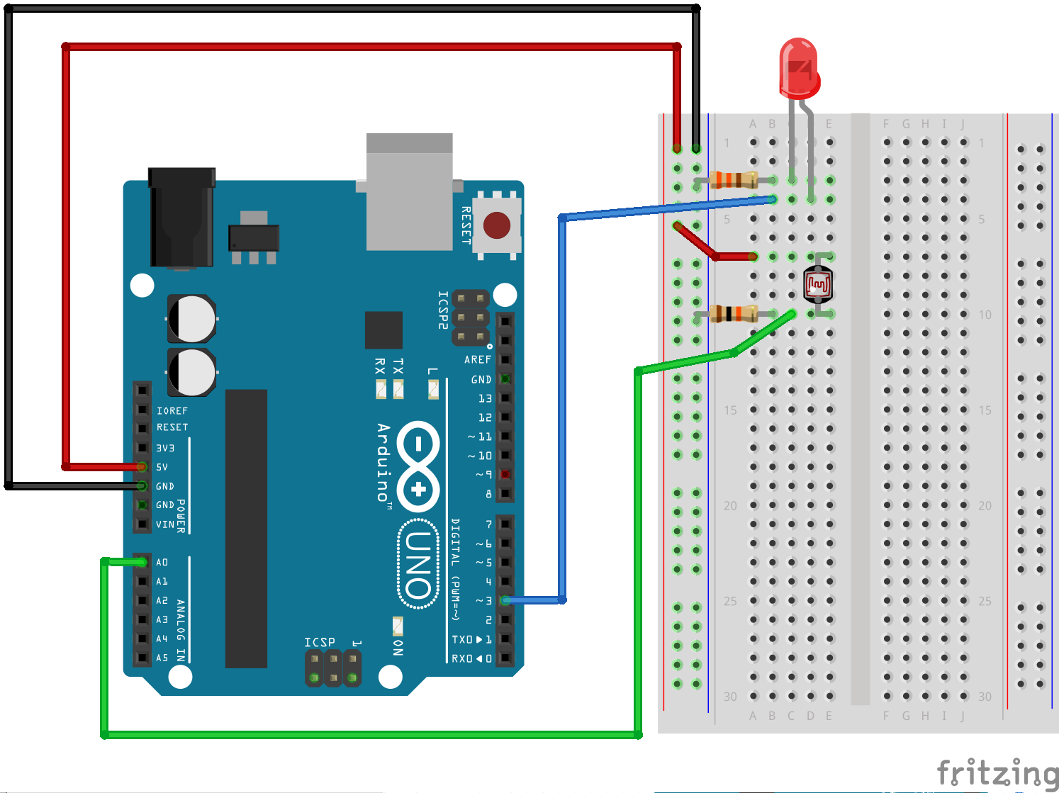
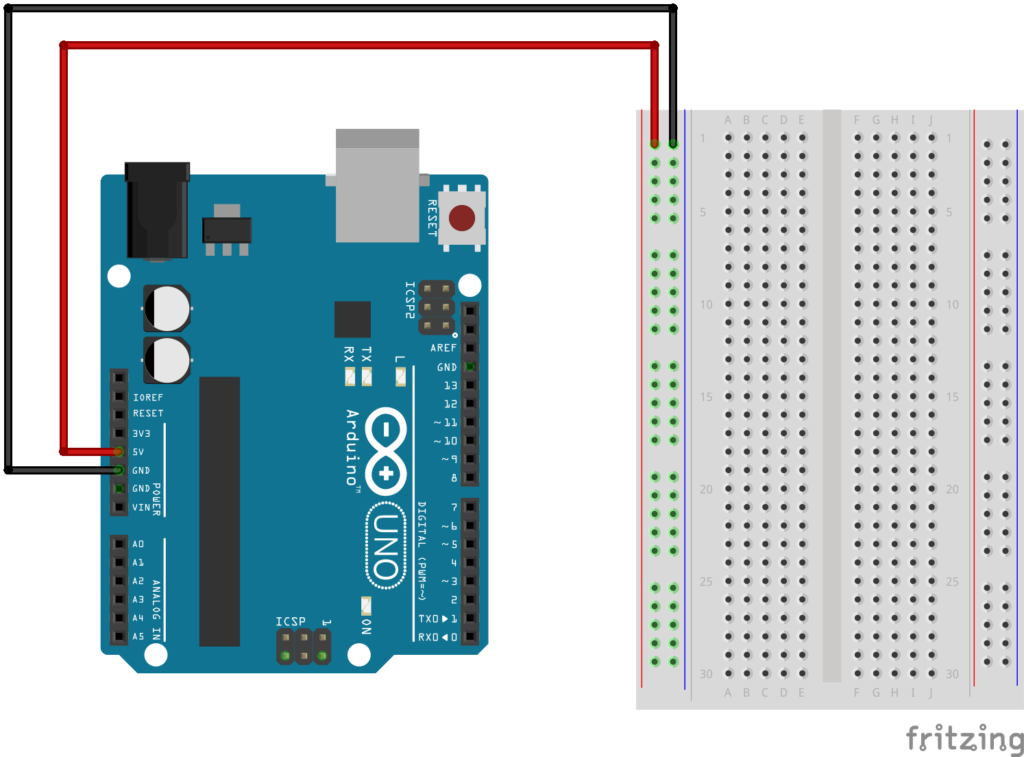
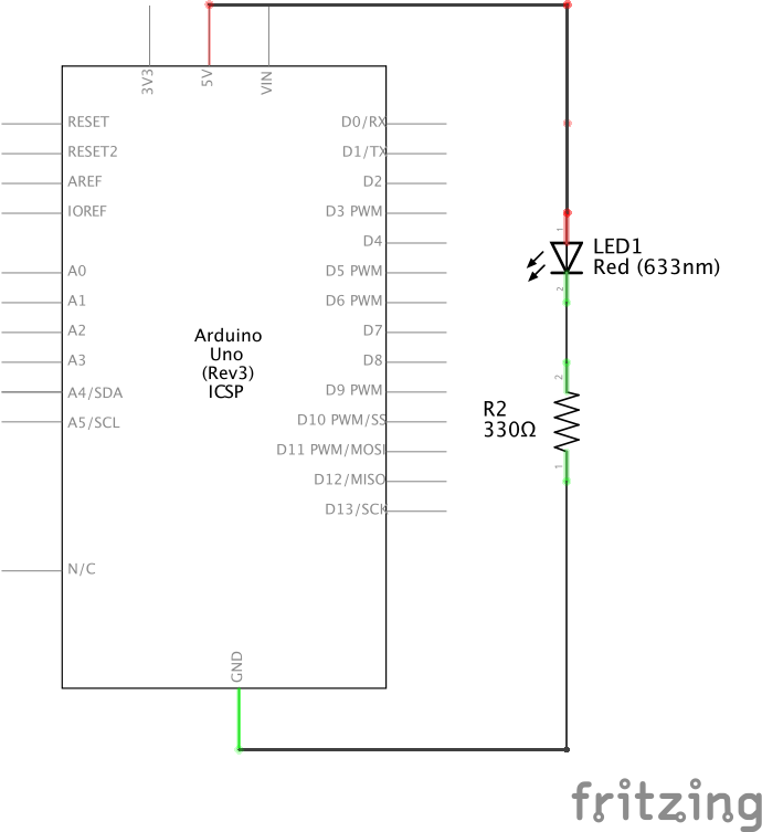
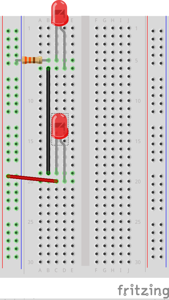
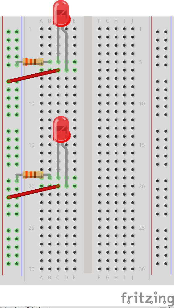
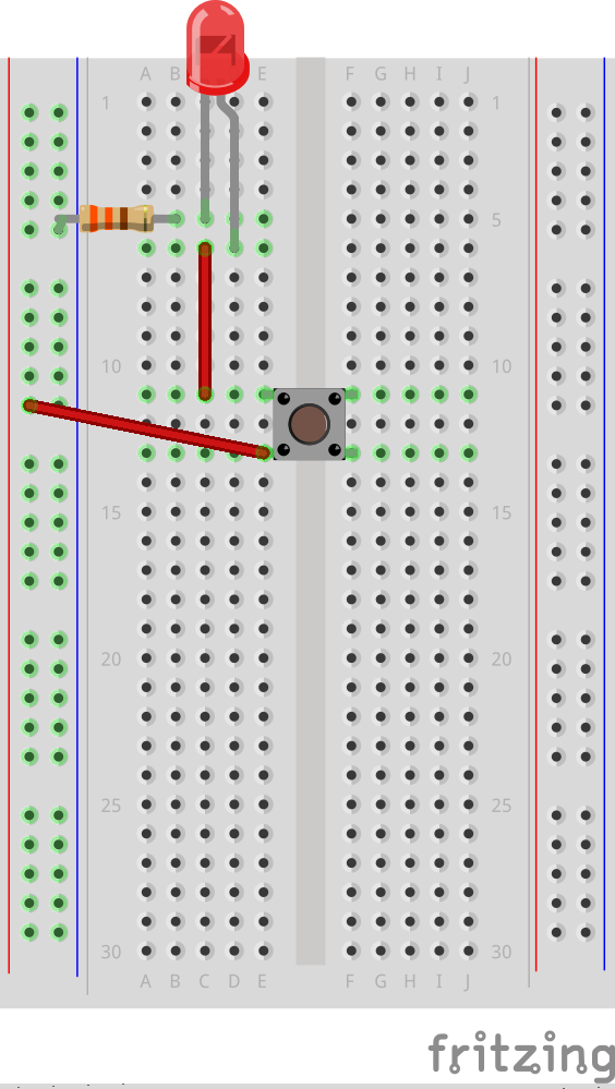
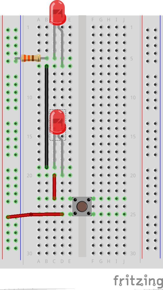
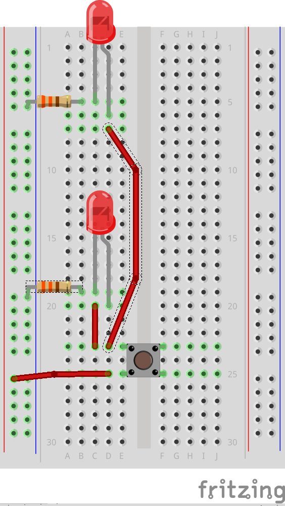
BREADBOARD & ARDUINO BOARD

Photos

VIDEO DEMO

CODES

void setup() {
  // put your setup code here, to run once:
  pinMode(4, INPUT);
  pinMode(2, OUTPUT);
  pinMode(3, OUTPUT);
}

void loop() {
  // put your main code here, to run repeatedly:
  if (bool digitalRead(4) == HIGH) {   //pressed, if the two aluminum foils touch
    digitalWrite(3, HIGH);        //turns on red LED
    digitalWrite(2, LOW);         //turns off green LED
  }
  else {                          //released, if the two aluminum foils part
    digitalWrite (3, LOW);        //turns off red LED
    digitalWrite(2, HIGH);        //turns on green LED
  };
}

CHALLENGES

  1. Maybe it’s some problems with my codes. The green light turns on immediately when the two aluminum foils touch. However, it takes 5 to 7 seconds for the boolean flips, and then the red light turns on.
  2. Sometimes when the foil connected to the resistor and the ground gets in contact with something conductive, green turns off and red turns on, signifying that the boolean flips. This may be a problem with the circuit, but I am still figuring it out.

Unusual Switch

This week, our assignment was to make an unusual switch that works without using our hands. For my project, I decided to make 2 switches that will turn on when the copper strip attached on the ground and the strip attached to your shoe touch (these are connected to the circuit via long wires). When they touch, the LED lights on either side will light up! So if you use your left foot, the yellow LED on the left will light up. If you use your right, the blue one on the right will light up.

I tried to make my circuit as neat as possible, so I organized my wires by color. Red ones are for power, black for GND, green for the left side, blue for the right. As for the longer wires, the ones connected to the strip on the ground are yellow, and the ones connected to your shoe are white. 

Here’s the code:

Basically, if the switch is on, the led will light up. If its not on (the strip in the floor and the shoe aren’t touching) the LED will turn off.

//R = right side, L= left side.

const int ledpinR = 2;
const int ledpinL = 3;

const int switchpinR = 4;
const int switchpinL = 5;

bool switchreadR;
bool switchreadL;

void setup() {
  // put your setup code here, to run once:
  pinMode(ledpinR, OUTPUT);
  pinMode(ledpinL, OUTPUT);

  pinMode(switchpinR, INPUT);
  pinMode(switchpinL, INPUT);

}

void loop() {
  // right LED code:
  
  switchreadR = digitalRead(switchpinR);

  if (switchreadR == true) {

    digitalWrite(ledpinR , HIGH );
  } else {
    digitalWrite(ledpinR , LOW);
  }

// left LED code:
  switchreadL = digitalRead(switchpinL);

  if (switchreadL == true) {

    digitalWrite(ledpinL , HIGH );
  } else {
    digitalWrite(ledpinL , LOW);
  }
}

Images:

The circuit
The bottom of the shoe


Video:

https://youtube.com/shorts/rRdpnEHXotk?feature=share

Buzz Off: An Unusual Switch

In this production assignment, we had to create an unusual switch that does not require the use of hands and involves digital input and output for interaction. For this, I created a buzz game, where touching the course using the loop would close the switch. This, in turn, would stop the green LED and the red LED will start blinking.

This unusual game requires you to move the loop across the course using wrists. Sounds interesting but it is pretty difficult. I spent so much time simplifying and making the course yet interesting. I am yet to find someone that could complete this with the loop between wrists and without buzzing the circuit.

Here’s the complete circuit :


Let’s play:

P.S Sorry for the bad video editing/ timing

The code is pretty simple and short. I have added a variable that keeps track of how many frames the switch has been closed –  a measure of how bad you are at this game.

//global variables
int ledPingreen = 2;
int ledPinred = 4;
int input_ledPin = 7;
int touches = 0;
unsigned long timer = 0;
int timerAmount = 50;
bool flip = false;

void setup() {
  // put your setup code here, to run once:
  pinMode(input_ledPin, INPUT);
  pinMode(ledPinred, OUTPUT);
  pinMode(ledPingreen, OUTPUT);
  
  //initiate timer
  timer = millis();

  //keep track of touches and monitor it
  touches = 0;
  Serial.begin(9600);
  
}

void loop() {
  //monitoring touches
  Serial.print("Number of touches until now : ");
  Serial.println(touches);

  //if the switch is closed
   if(digitalRead(input_ledPin)==HIGH){
    //increment number of touches
    touches += 1;
    //blink the red LED
    if(millis()>= timer){
      flip = !flip;
      digitalWrite(ledPinred, flip);
      timer = millis()+timerAmount;
    }
    //turn of green LED
    digitalWrite(ledPingreen, LOW);
   }

   //if open
   else{
    //turn green LED on and red off
    digitalWrite(ledPinred, LOW);
    digitalWrite(ledPingreen, HIGH);
   }
}

Week 8 The Switch

Description:

I have always been the worst when it came to forgetting different things at different places. Forgetting my card at the most random places was getting me locked out of my room more than I would have liked. So I decided to make a switch that reminds you to put your card back in its place sometime out.

I started by placing a switch in the circuit and making it work using a normal push-button switch. once I finished the circuit I replaced one end of the switch with a wire connected to the card and the other end with a wire connected to a cardholder that is to be stuck to a phone.

I connected the wires to copper tape that I stuck on contacting sides of the card and the cardholder so that when the card is in place, the switch is closed.

I used a yellow led light for the normal time when the card is placed in its location. when you remove the card from the cardholder, a timer starts, when the time span in the code ends, the red light starts to blink to remind you to put the card back in.

IMAGES:

Breadboard Circuit:

Whole Circuit:

Card Connection

Video:

CODE:

long mytime=500, timer = 0;
const int outs[] = {2, 4};
const int ins = A2;
int curr = 0, prev=0;
bool flip=false;
long blinkk=0;

void setup() {
  // put your setup code here, to run once:
  Serial.begin(9600);
  for (int i = 0; i < sizeof(outs); i++) {
    pinMode(outs[i], OUTPUT);
  }
  pinMode(ins, INPUT);
}

void loop() {
  curr = digitalRead(ins);// <500, <900, >900
  if (curr == 0) {
    Serial.print(timer);
    Serial.print(" ");
    Serial.println(mytime);
    if (mytime == timer) {
      if(blinkk<=millis()){
        flip=!flip;
        blinkk+=500;
      }
      digitalWrite(outs[0], flip);
      digitalWrite(outs[1], LOW);
    }
    else{
      timer+=1;
      digitalWrite(outs[0], LOW);
      digitalWrite(outs[1], LOW);
    }
  }
  else {
    {
      timer=0;
      digitalWrite(outs[1], HIGH);
      digitalWrite(outs[0], LOW);
      blinkk=millis();
    }
  }
  prev = digitalRead(ins);
}


Handless Switch : Sleep No More!

Description

Create an unusual switch that doesn’t require the use of your hands. Use Arduino digital input and output for the interaction.

Inspiration

Imagine you could identify all the listeners who sleep during your speaking sessions even if the listener sleeping is at the backbench. All you need is a LED that is positioned at a visible location and turns on immediately, a listener puts his or her head on the table.

Process

I started off by creating a simple circuit with an LED. I added a digital input pin on the Arduino and then, with code, I take the input and turn on the LED as a digital output. By bringing together the power pinned down by the resistor and the buttonPin, the LED turns on and when separated goes off. In order to bring the two together, I attached one to the forehead and the other to the table.

Final Work

Challenges

I wanted to attach one of the cables to my neck and the other one under my chin but it never worked so I decided to go with the idea above.

Code
const int ledPin = 2;
const int buttonPin = 3;


bool onOff = false;
bool prevButtonState = LOW;

void setup() {
   pinMode(ledPin, OUTPUT);
    pinMode(buttonPin, INPUT);

}

void loop() {
  
  bool currentState = digitalRead(buttonPin);
  
 if(currentState == HIGH){
      digitalWrite(ledPin, true);
    }

  else{
    
     digitalWrite(ledPin, false);
    }


}


Bell the Cat – A Carnival Switch Ring Toss

For this week’s assignment, we had to make a switch using Arduino digital input and output for interaction. I started off with the idea of a switch where when you put a hat on a cat figurine, the light would switch on. But I scrapped that idea since it would involve using my hands.

So, I decided to adapt my idea to lower the degree of interaction hands may have on the switch. I ended up with a carnival-like game Ring toss, where you win if you throw a ring and it goes on a bottle. In my version, the bottle is a cat, and I’m throwing a ring of aluminum foil. When the ring falls on the cat, the green light glows and you win.

For this, I had two jumper wires from the breadboard attached to aluminum foil and this was pasted to the cat’s ears and body, and the ring was made of aluminum foil as well. So when the ring fell on the cat, the aluminum foil would complete the circuit which would go as Arduino digital input. 

I had some trouble understanding how to incorporate Arduino digital input so after playing around with the push button switch schematic, I realized what the assignment meant. 

Here’s the video showing the switch and there’s pictures of the whole setup below it.

The Setup
The Setup – Cat

Week 8: Hands-free switch

Inspiration:

For this assignment, I was mainly inspired by the UV shoe sanitizer that is used to help fight bacteria in hospitals.

Process:

For the circuit, I have used 5 LEDs ( 4 red, 1 green), 8 wires, and one 320Ω resistor. The basic idea is that the individual waits for the green light to put his shoe on the platform, then the disinfection starts and takes 5 seconds to complete, when the green light goes on again, the individual can then remove his shoe.

View post on imgur.com

Platform:

View post on imgur.com

Setup:

I have used a for() loop and pinMode to avoid unnecessary repetition. I also have an array to store all the LEDs.

void setup() {
  pinMode(7, OUTPUT);
  for (int i=0; i<4; i++){
    pinMode(Led[i], OUTPUT);
  }
}
LEDs:

To tell the user that the disinfection is still going on, I have added an animation to the red LEDs, in which the light bounces between the two edges of the strip. To do that, I used the Delay function as well as two for() loops (for each direction), and digitalWrite() to control the LEDs.

// Check when the shoe is sanitized
if (DONE){
  for (int i=0; i<4; i++){
    digitalWrite(Led[i], LOW);
    digitalWrite(7, HIGH);
  }
}

// If not sanitized
if (DONE==false){
  digitalWrite(7, LOW);
  // One way, left to right
  for (int i=0; i<4; i++){
    // 2 Leds at the same time
    digitalWrite(Led[i], HIGH);
    digitalWrite(Led[i+1], HIGH);
    // Delay of 120
    delay(120);
    digitalWrite(Led[i], LOW);
    digitalWrite(Led[i+1], LOW);}
  // The other way , right to left
  for (int i=3; i>=0; i--){
    digitalWrite(Led[i], HIGH);
    digitalWrite(Led[i-1], HIGH);
    delay(120);
    digitalWrite(Led[i], LOW);
    digitalWrite(Led[i-1], LOW);
  }
}
Timer:

For the timer, I have used millis() to change a boolean variable every 5 seconds.

// Timer for the sanitization
unsigned long curr = millis();
if (curr-prev>=5000){
  prev=curr;
  DONE=!DONE;
}

One of the challenges I faced was setting up a good connection between wires as the tape was not ideal.

Demo:

View post on imgur.com

Code:
int Led[]= {9, 10, 11, 12}; // list of Leds
boolean DONE= false; // check when the sanitization is done
unsigned long prev=0; // for the timer

void setup() {
  pinMode(7, OUTPUT);
  for (int i=0; i<4; i++){
    pinMode(Led[i], OUTPUT);
  }
}

void loop() {
  // Timer for the sanitization
  unsigned long curr = millis();
  if (curr-prev>=5000){
    prev=curr;
    DONE=!DONE;
  }
  
  // Check when the shoe is sanitized
  if (DONE){
    for (int i=0; i<4; i++){
      digitalWrite(Led[i], LOW);
      digitalWrite(7, HIGH);
    }
  }

  // If not sanitized
  if (DONE==false){
    digitalWrite(7, LOW);
    // One way, left to right
    for (int i=0; i<4; i++){
      // 2 Leds at the same time
      digitalWrite(Led[i], HIGH);
      digitalWrite(Led[i+1], HIGH);
      // Delay of 120
      delay(120);
      digitalWrite(Led[i], LOW);
      digitalWrite(Led[i+1], LOW);}
    // The other way , right to left
    for (int i=3; i>=0; i--){
      digitalWrite(Led[i], HIGH);
      digitalWrite(Led[i-1], HIGH);
      delay(120);
      digitalWrite(Led[i], LOW);
      digitalWrite(Led[i-1], LOW);
    }
  }
}


Week 8 – Sitting changes colour

Description

Create an unusual switch that doesn’t require the use of your hands. Use Arduino digital input and output for the interaction.

Process

So, I was just sitting on my chair trying to think about what to make. I got the idea, why don’t I just make something that involves sitting on the chair. So here it goes.

I used two LEDs ( red and blue). I used 3 resistors ( two 330 v and one 10k) to control the flow of electricity. I used basic conductors wires and jumper twins to finish the circuit. I connected the Red LED to Digital Input 13, Blue LED to Digital Input 12. I connected the switch to 7.

I connected the copper wires to the copper tape to give it a bigger surface area to conduct electricity.

This is the final video of me testing out the product:-

The code was pretty simple.

HERE IT GOES:-

const int ledRed = 13;
const int switch1 = 7;
const int ledBlue = 12;
bool currentState = false;
bool switchState = LOW;

void setup() {
  // put your setup code here, to run once:
  pinMode(ledRed, OUTPUT);
  pinMode(ledBlue, OUTPUT);
  pinMode(switch1, INPUT);
}

void loop() {

///put your main code here, to run repeatedly:
    switchState = digitalRead(switch1);
    if (currentState != switchState ){
      digitalWrite(ledBlue, LOW);
      digitalWrite(ledRed, HIGH);
     } else {
      digitalWrite(ledBlue, HIGH);
      digitalWrite(ledRed, LOW);
    }

}

Analog Input & Output

Potentiometer:

Inside a potentiometer:
potentiometer1.gif (472×323)

Photoresistor:

Pulse Width Modulation:
What is PWM: Pulse Width Modulation

const int ledPin = 2;
bool ledState = LOW;

// a really longer number with no + or - sign
unsigned long toggleTime = 0;
int triggerInterval = 500;

void setup() {
  pinMode(ledPin, OUTPUT);
  Serial.begin(9600);
}

void loop() {
  // read the analog input
  int knobValue = analogRead(A0);
  // map that input to a range appropriate for our use
  // in this case, we take the range of the photocell and map it to millis between 10 & 500
  // this is the blink interval for the LED
  triggerInterval = map(knobValue, 190, 860, 10, 500);

  // print out the original value and the mapped value on the same line
  Serial.print(knobValue);
  Serial.print(" ");
  Serial.println(triggerInterval);

  // if the current time (millis) is more than the exact time when we are supposed to toggle
  if (millis() > toggleTime) {
    // flip the LED to the opposite of what it was
    ledState = !ledState;
    // set the next time the LED should toggle
    // to the current time + whatever the blink interval amount of time is
    toggleTime = millis() + triggerInterval;
  }

  // turn the LED on or off based on the ledState vaviable
  digitalWrite(ledPin, ledState);
}


Arduino First Steps!

Electricity slides from class

Basic Circuits:

518c0b34ce395fea62000002.jpg (1000×669)

Series

Parallel

Button

Series with Button

Parallel with Button


Digital Read and Write:

Digital Read a button on pin 2 and digital write an LED on pin 3:

Remember to include a 330 ohm resistor for the LED and a 10k ohm pull down resistor to ground for the button.

int buttonPin = 2;
int ledPin = 3;
int ledState = LOW;
int prevButtonState = LOW;

void setup() {
  // set pin modes
  pinMode(ledPin, OUTPUT);
  pinMode(buttonPin, INPUT);
  // needed in order to start serial communication
  Serial.begin(9600);
}

// PSUEDO CODE:
// check if button is currently pressed
// if button is pressed then check to see if it was pressed during the last frame too
// (we need to remember our button state)
// if button is bressed and previous button is not pressed then flip our LED state

 void loop() {
  // check to see what state our button is in, and store that information
  int currentButtonState = digitalRead(buttonPin);

  // if the button is currently being prssed down, AND during the last frame is wasn't pressed down
  if (currentButtonState == HIGH && prevButtonState == LOW) {
      // flip the LED state
      if (ledState == HIGH){
        ledState = LOW;
      } else if (ledState == LOW){
        ledState = HIGH;
      }
  }
  // if you want to print out the LED state
//  Serial.println(ledState);

  // set our LED to turn on and off according to our variable that we flip above
  digitalWrite(ledPin, ledState);

  //we need to remember the state of our button for the next time through LOOP
  prevButtonState = currentButtonState;
}

Resistor Color Code Calculator