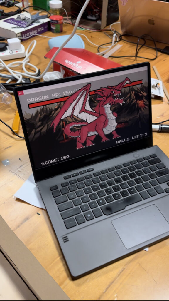
Concept
Fruitfall Frenzy is an entertaining and straightforward catching game where players aim to accumulate points by catching fruits while avoiding junk food to prevent point deductions. To achieve victory, players must collect fruits and reach a score of 15 or more. However, failing to do so and catching 10 junk foods with a score of 0 results in a loss for the player.
link to the game: https://editor.p5js.org/Javeria/sketches/e-4vC95i_
Implementation
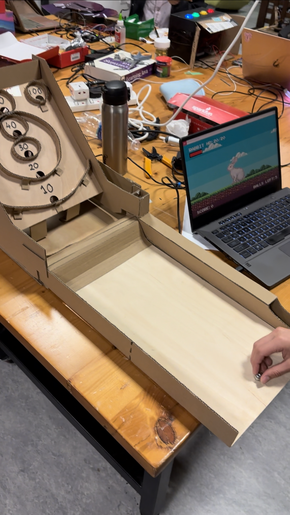
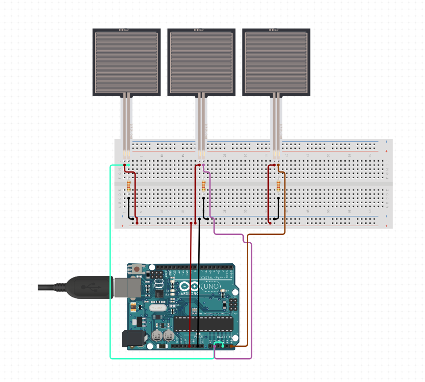
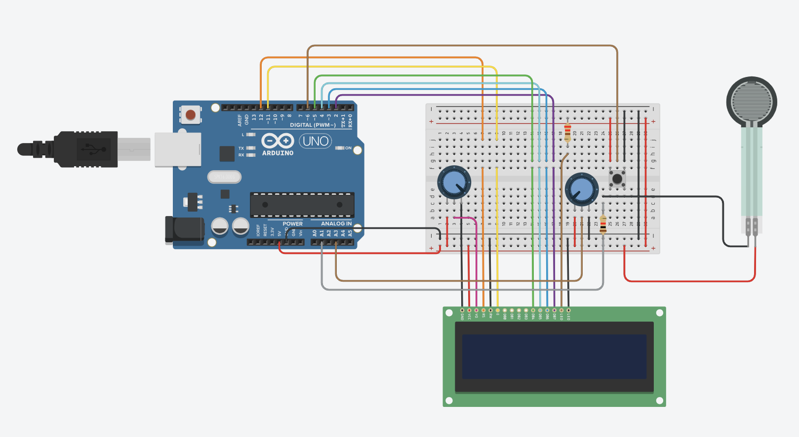
In terms of interaction, I’ve incorporated two buttons on the breadboard to facilitate the control of the basket’s left and right movements. The Arduino integration is seamlessly implemented, with the readSerial() function acting as the communication bridge between p5.js and Arduino. The Arduino code is designed to read the status of two switches and relay these values to p5.js. On the other hand, p5.js takes charge of displaying the game graphics, playing sounds, and managing the overall game logic.
p5js Code:
let basket;
let fruits = [];
let junkFoods = [];
let score = 0;
let gameOver = false;
let startPage;
let front;
let instructions;
let gifImage;
let win;
let lose;
let junkFoodsCaught = 0;
let gameStarted = false;
let instructionMode = false;
let customFont;
let gameWon = false;
let switch1State, switch2State;
let startmusic;
let winmusic;
let lossmusic;
let gamemusic;
let fruitmusic;
let junkfoodmusic;
let currentMusic;

let basketImg, backgroundImage;
let fruitImages = [];
let junkFoodImages = [];

function preload() {
  customFont = loadFont('Sunday Happy.ttf');
  startPage = loadImage('1.png');
  instructions = loadImage('2.png');
  basketImg = loadImage('basket.png');
  backgroundImage = loadImage('background.png');
  win = loadImage('win.png'); // Add this line
  lose = loadImage('lose.gif'); // Add this line
  startmusic = loadSound ('start.mp3');
  winmusic  = loadSound ('win.mp3');
  lossmusic  = loadSound ('loss.mp3');
  gamemusic  = loadSound ('game.mp3');
  fruitmusic  = loadSound ('fruit.mp3');
  junkfoodmusic  = loadSound ('junkfood.mp3');

  // Load different fruit images
  for (let i = 1; i <= 5; i++) {
    fruitImages.push(loadImage('fruit' + i + '.png'));
  }

  // Load different junk food images
  for (let i = 1; i <= 2; i++) {
    junkFoodImages.push(loadImage('junkfood' + i + '.png'));
  }
}

function setup() {
  createCanvas(620, 650);
  setupGame();
  currentMusic = startmusic;
  currentMusic.play();
}

function setupGame() {
  basket = new Basket(basketImg);

  // Limit the initial number of falling elements
  const initialFruitsCount = 2; // Adjust this value as needed
  const initialJunkFoodsCount = 2; // Adjust this value as needed

  for (let i = 0; i < initialFruitsCount; i++) {
    fruits.push(createRandomFruit());
  }

  for (let i = 0; i < initialJunkFoodsCount; i++) {
    junkFoods.push(createRandomJunkFood());
  }
}

function drawGame() {
  // Draw background image
  image(backgroundImage, 0, 0, width, height);

  basket.display();
  basket.move();

  // Add new fruits and junk foods based on certain conditions
  if (frameCount % 60 === 0 && fruits.length + junkFoods.length < 5) {
    // Check if there's enough space for a new fruit
    if (fruits.length < 2) {
      fruits.push(createRandomFruit());
    }

    // Check if there's enough space for a new junk food
    if (junkFoods.length < 2) {
      junkFoods.push(createRandomJunkFood());
    }
  } }
 //<-- Add this closing bracket

function draw() {
  background(250);

  if (gameWon) {
    // Player wins
    currentMusic.stop(); // Stop the current music
    winmusic.play();    // Play the win music
    currentMusic = winmusic;
    drawWinPage();
     currentMusic.stop(); // Stop the current music
    winmusic.play();    // Play the win music
    currentMusic = winmusic; // Update currentMusic
  } else if (gameOver) {
    // Player loses
    drawLosePage();
    currentMusic.stop(); // Stop the current music
    lossmusic.play();   // Play the lose music
    currentMusic = lossmusic; // Update currentMusic
  } else {
    if (instructionMode) {
      // Display instructions
      image(instructions, 0, 0, width, height);
      fill(255, 204, 0, 180);
      noStroke();
      rect(535, 524, 70, 35);
      fill(0);
      textSize(30);
      textFont(customFont);
      text("Back", 542, 549);
       if (currentMusic !== startmusic) {
        currentMusic.stop(); // Stop the current music if it's not start music
        startmusic.play();  // Play the start music
        currentMusic = startmusic; // Update currentMusic
      }


    } else {
      // Display the start page
      image(startPage, 0, 0, width, height);
      fill(255, 204, 0, 180);
      noStroke();
      rect(228, 335, 150, 35);
      fill(0);
      textSize(30);
      textFont(customFont);
      text("Start Game", 237, 359);
      fill(255, 204, 10, 180);
      noStroke();
      rect(227, 391, 150, 35);
      fill(0);
      textSize(30);
      textFont(customFont);
      text("Instructions", 235, 417);


      // Draw game elements if the game has started
      if (gameStarted) {
        drawGame();
         if (currentMusic !== gamemusic) {
          currentMusic.stop(); // Stop the current music if it's not game music
          gamemusic.play();   // Play the game music
          currentMusic = gamemusic; // Update currentMusic
      }
    }
  }
}
}


function drawWinPage() {
  // Draw the win background image
  image(win, 0, 0, width, height);
  fill(255, 204, 0, 180);
      noStroke();
      rect(247, 266, 140, 35);
      fill(0);
      textSize(30);
      textFont(customFont);
      text("Restart", 272, 290);


  if (mouseIsPressed && mouseX > 247 && mouseX < 387 && mouseY > 266 && mouseY < 301){


    restartGame();
   }

}

function drawLosePage() {
  // Draw the lose background image
  image(lose, 0, 0, width, height);
  fill(255, 204, 0, 180);
      noStroke();
      rect(247, 592, 150, 35);
      fill(0);
      textSize(30);
      textFont(customFont);
      text("Restart", 280, 616);


   if (mouseIsPressed && mouseX > 247 && mouseX < 397 && mouseY > 592 && mouseY < 627) {
    restartGame();
   }


}
function restartGame() {
  gameOver = false;
  gameStarted = false;
  score = 0;
  junkFoodsCaught = 0;
  gameWon = false;
  setupGame();
}

function mousePressed() {
  if (!gameStarted) {
    if (instructionMode) {
      // Handle mouse click to return to the main menu
      if (mouseX > 535 && mouseX < 605 && mouseY > 524 && mouseY < 559) {
        instructionMode = false;
      }
    } else {
      if (mouseX > 228 && mouseX < 378) {
        if (mouseY > 335 && mouseY < 370) {
          // Start the game
          gameStarted = true;
          setupGame(); // Call setupGame when the game starts
        } else if (mouseY > 391 && mouseY < 426) {
          // Show instructions
          instructionMode = true;
        }
      }
    }
  }
}


class Basket {
  constructor(img) {
    this.width = 200;
    this.height = 150;
    this.x = width / 2 - this.width / 2;
    this.y = height - this.height - 10;
    this.img = img;
  }

  display() {
    image(this.img, this.x, this.y, this.width, this.height);
  }

  move() {
    if (keyIsDown(LEFT_ARROW) && this.x > 0) {
      this.x -= 5;
    }
    if (keyIsDown(RIGHT_ARROW) && this.x < width - this.width) {
      this.x += 5;
    }
  }

  moveLeft() {
    if (this.x > 0) {
      this.x -= 5;
    }
  }

  moveRight() {
    if (this.x < width - this.width) {
      this.x += 5;
    }
  }
}


class Fruit {
  constructor(img) {
    this.x = random(width);
    this.y = 0;
    this.diameter = 120;
    this.img = img;
  }

  display() {
    image(this.img, this.x - this.diameter / 2, this.y - this.diameter / 2, this.diameter, this.diameter);
  }

  fall() {
    this.y += 5;
  }

  intersects(basket) {
    let halfBasket = basket.width / 2;
    return (
      this.x > basket.x - halfBasket &&
      this.x < basket.x + basket.width + halfBasket &&
      this.y > basket.y &&
      this.y < basket.y + basket.height
    );
  }

  intersectsBasket(basket) {
    let halfBasket = basket.width / 2;
    return (
      this.x > basket.x - halfBasket &&
      this.x < basket.x + basket.width + halfBasket &&
      this.y + this.diameter / 2 > basket.y &&
      this.y - this.diameter / 2 < basket.y + basket.height
    );
  }
}


class JunkFood extends Fruit {
  constructor(img) {
    super(img);
    this.diameter = 60;

  }

  // Override the intersectsBasket method
  intersectsBasket(basket) {
    let halfBasket = basket.width / 2;
    return (
      this.x > basket.x - halfBasket &&
      this.x < basket.x + basket.width + halfBasket &&
      this.y + this.diameter / 2 > basket.y &&
      this.y - this.diameter / 2 < basket.y + basket.height
    );
  }
}

function drawGame() {
  // Draw background image
  image(backgroundImage, 0, 0, width, height);

  basket.display();
  basket.move();

  if (frameCount % 60 === 0) {
    fruits.push(createRandomFruit());
    junkFoods.push(createRandomJunkFood());
  }

  for (let i = fruits.length - 1; i >= 0; i--) {
    fruits[i].display();
    fruits[i].fall();

    if (fruits[i].intersects(basket)) {
      score += 1;
      fruits.splice(i, 1);
    } else if (fruits[i].y > height) {
      fruits.splice(i, 1);
    }
  }

  for (let i = junkFoods.length - 1; i >= 0; i--) {
    junkFoods[i].display();
    junkFoods[i].fall();

    if (junkFoods[i].intersects(basket)) {
      score -= 1; // Deduct score if junk food touches the basket
      junkFoods.splice(i, 1);
    } else if (junkFoods[i].y > height) {
      junkFoods.splice(i, 1);
    }
  }

  textSize(20);
  fill(0);
  text("Score: " + score, 20, 30);

  // Check win condition
  if (score >= 10) {
    gameWon = true;
    drawWinPage();
  }

  // Check lose condition
  if (score < 0 || junkFoodsCaught >= 10) {
    gameOver = true;
    drawLosePage();
  }
}

function createRandomFruit() {
  let randomFruitImg = random(fruitImages);
  let fruit = new Fruit(randomFruitImg);

  for (let existingFruit of fruits) {
    while (fruit.intersects(existingFruit) || fruit.intersectsBasket(basket)) {
      fruit = new Fruit(randomFruitImg);
    }
  }

  return fruit;
}

function createRandomJunkFood() {
  let randomJunkFoodImg = random(junkFoodImages);
  let junkFood = new JunkFood(randomJunkFoodImg);

  for (let existingFruit of fruits) {
    while (junkFood.intersects(existingFruit) || junkFood.intersectsBasket(basket)) {
      junkFood = new JunkFood(randomJunkFoodImg);
    }
  }
  for (let existingJunkFood of junkFoods) {
    while (junkFood.intersects(existingJunkFood) || junkFood.intersectsBasket(basket)) {
      junkFood = new JunkFood(randomJunkFoodImg);
    }
  }

  return junkFood;
}
function keyPressed() {
  // Handle key presses (this function only detects if a key is pressed at the moment)
}
function readSerial(data) {
  ////////////////////////////////////
  //READ FROM ARDUINO HERE
  ////////////////////////////////////

  if (data != null) {
    // make sure there is actually a message
    // split the message
    let fromArduino = split(trim(data), ",");
    console.log(fromArduino);
    // if the right length, then proceed
    if (fromArduino.length == 2) {
      // only store values here
      // do everything with those values in the main draw loop

      // We take the string we get from Arduino and explicitly
      // convert it to a number by using int()
      // e.g. "103" becomes 103
      switch1State = int(fromArduino[0]);
      switch2State = int(fromArduino[1]);

      if (switch1State) {
        basket.moveLeft();
      }

      if (switch2State) {
        basket.moveRight();
      }
    }

    //////////////////////////////////
    //SEND TO ARDUINO HERE (handshake)
    //////////////////////////////////
    let sendToArduino = "\n";
    writeSerial(sendToArduino);
  }
}


function keyPressed(){
  setUpSerial();
}
Arduino Code:
const int switch1Pin = 4;
const int switch2Pin = 8;

void setup() {
  Serial.begin(9600);
  pinMode(switch1Pin, INPUT_PULLUP);
  pinMode(switch2Pin, INPUT_PULLUP);


  while (Serial.available() <= 0 ){
    Serial.println("0,0");
    delay(300);
  }
}

void loop() {


  while(Serial.available()) {
    if (Serial.read() == '\n') {
      int switch1State = digitalRead(switch1Pin);
      delay(5);
      int switch2State = digitalRead(switch2Pin);

      Serial.print(switch1State);
      Serial.print(',');
      Serial.println(switch2State);
    }
  }


}
Future improvements
To enhance both the engagement and challenge levels of the game, I’m considering incorporating additional features. These may include the gradual escalation of difficulty as the game progresses and the introduction of power-ups to provide players with unique advantages.
User Testing
In the testing phase, I asked Nafiha to give my game a try. Impressively, she seamlessly utilized the buttons to navigate the basket without any hesitation. Her feedback highlighted that the controls were straightforward, requiring no additional instructions. Taking her suggestion into account, I modified the game dynamics by initially decreasing the number of falling objects and contemplating a gradual increase over time, resulting in a more balanced and enjoyable gameplay experience.
https://drive.google.com/file/d/1_36pcfyrhlTWxp_WqHmETfE6l8cfDicl/view?usp=sharing

 p5.js battle!