Concept:
Honestly, we had some trouble brainstorming for this assignment at first. We weren’t sure what instrument to create or mimic and how. However, after watching a video about the theremin we decided to make an instrument that would react to the distance between our hands and some sensor. We also wanted to recreate the drone of old midi modulating synths.
For that, we needed to use an ultrasonic distance finder and the HC-SR04 sensor in our kit was perfect for that. Also, we wanted to be able to control the itch of the sound being produced so we used a potentiometer for that. We decided to use a speaker available at the IM lab, a switch, and an enclosure to build the whole project.
Brainstorming:
While looking for inspiration and knowledge necessary for implementing our idea we came across the following youtube video that outlined how to make a simple ‘instrument’ using an ultrasonic distance sensor:
Musical Instrument Using Arduino + Ultrasonic Distance Sensor
This video allowed us to build a device that could convert distance measurements into different musical notes.
After this, we used some other sources to understand better the use of ultrasonic distance sensors and also how to integrate switches and potentiometers into the circuit:
Arduino Potentiometer – Complete Tutorial
Ultrasonic Sensor HC-SR04 with Arduino Tutorial
Process & Code
For the code, it was a bit difficult to figure out how to use the ultrasonic range finder at first. We had to figure out how to convert time to distance since the sensor needs to listen for a pulse from an object to return and the returning pulse is proportional to the distance of the object from the sensor. Luckily, we found exactly what we were looking for in a tutorial on the internet. However, it was calibrated for a few meters instead of a few inches. We needed something that was more sensitive and produced a different set of frequencies. We decided that we would do that by reducing the maximum distance to a few inches and increasing the sensitivity. We also tweaked the code to put the speaker in a continuous loop instead of just beeps to give us a more synth-esque sound.
The sensor itself was difficult to calibrate but after referring to the aforementioned sources we were able to discover some useful functions like the delayMicroseconds() and microsecondstoInches()
// The ping is triggered by a HIGH pulse of 2 or more microseconds.
// Give a short LOW pulse beforehand to ensure a clean HIGH pulse:
pinMode(3, OUTPUT);// attach pin 3 to Trig
digitalWrite(3, LOW);
delayMicroseconds(2);
digitalWrite(3, HIGH);
delayMicroseconds(5);
digitalWrite(3, LOW);
cm = microsecondsToCentimeters(duration);
For the potentiometer, we added the following code to make it emit certain frequencies of sound depending on the position of the knob:
int potVal= analogRead(potentiometerPin);
int speakerVal = potVal * 5  ;
Serial.println((String)potVal + " -> " + (String) speakerVal);
tone(speakerPin, speakerVal );
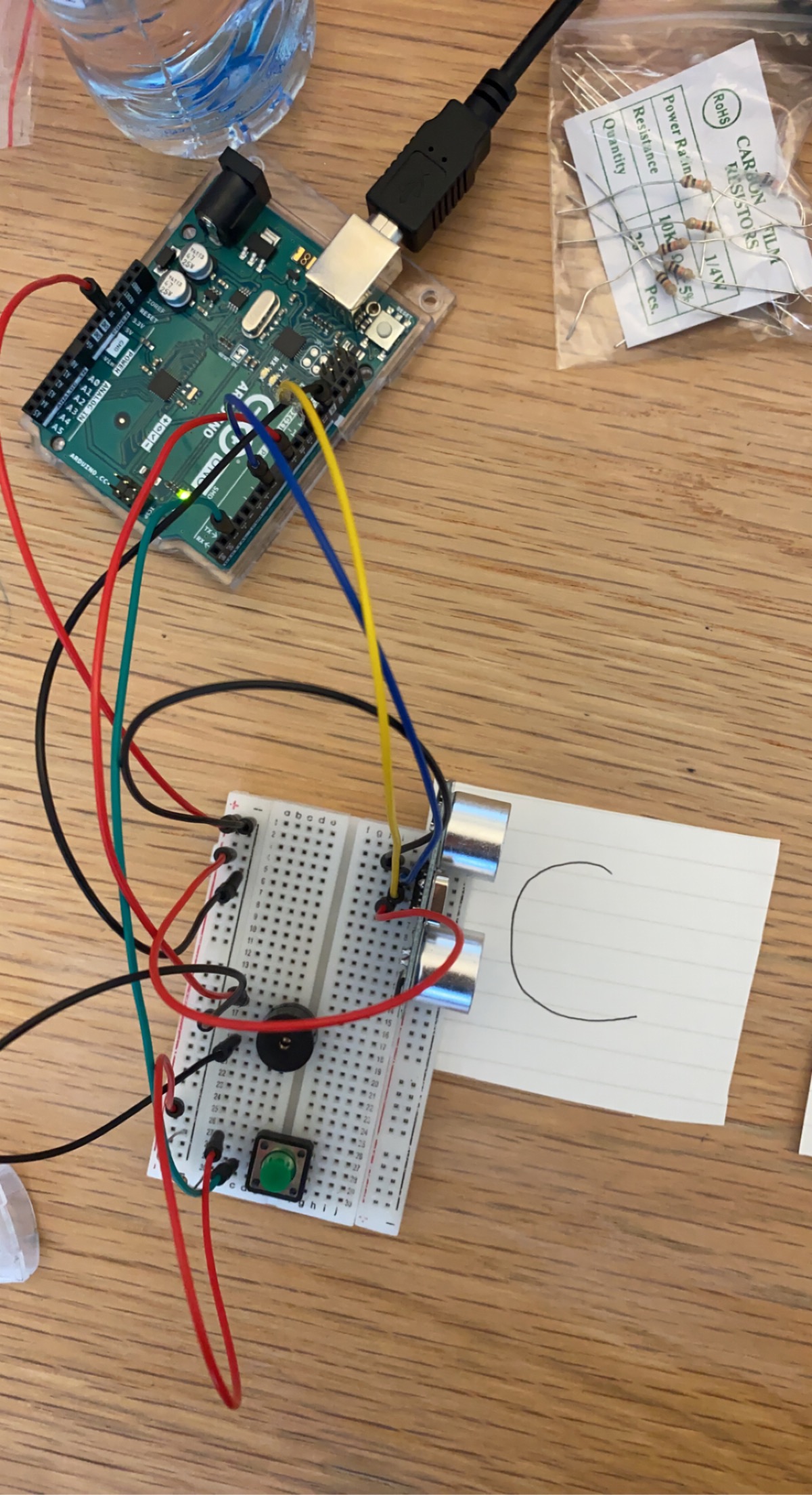
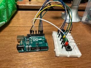
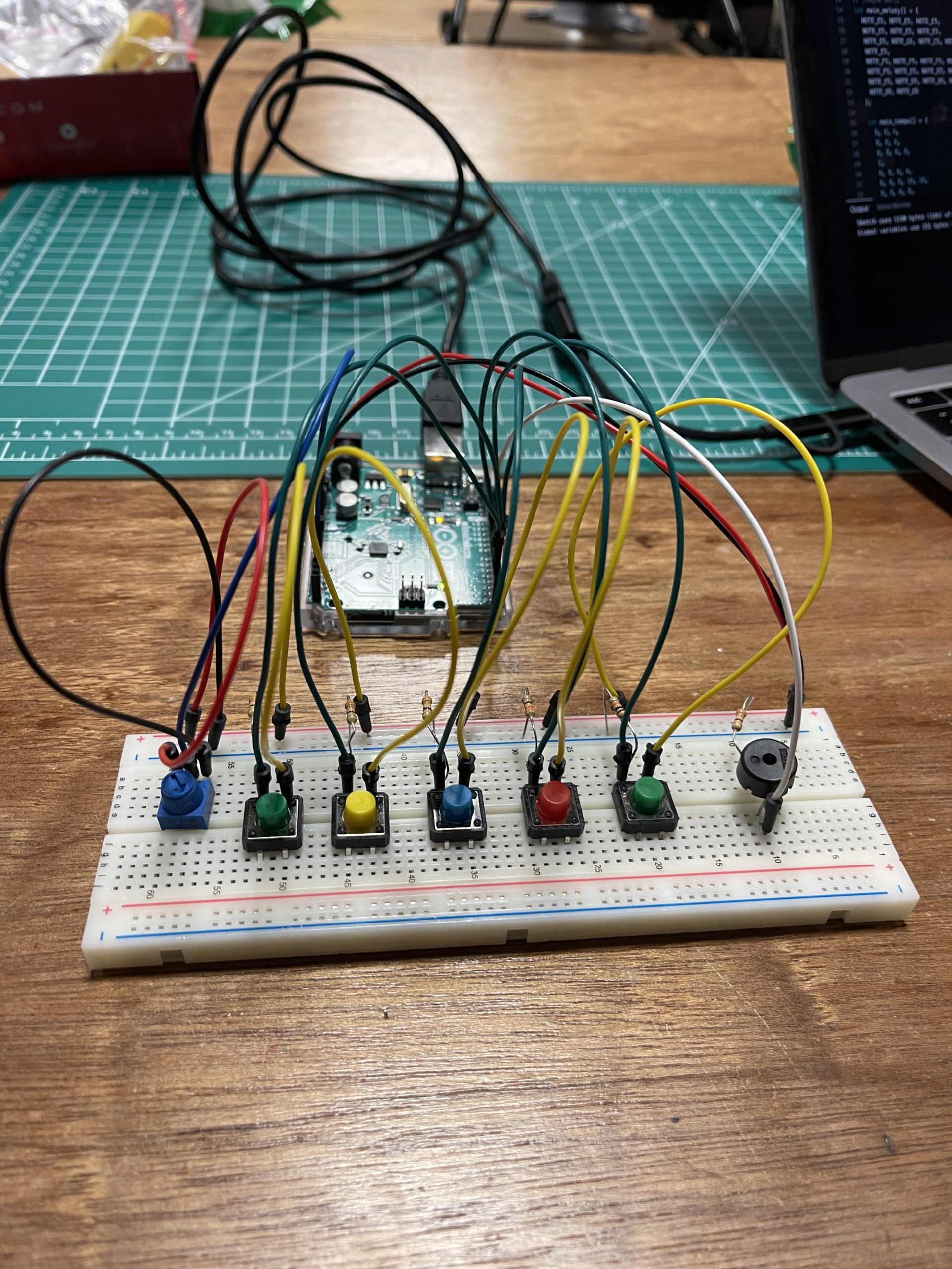
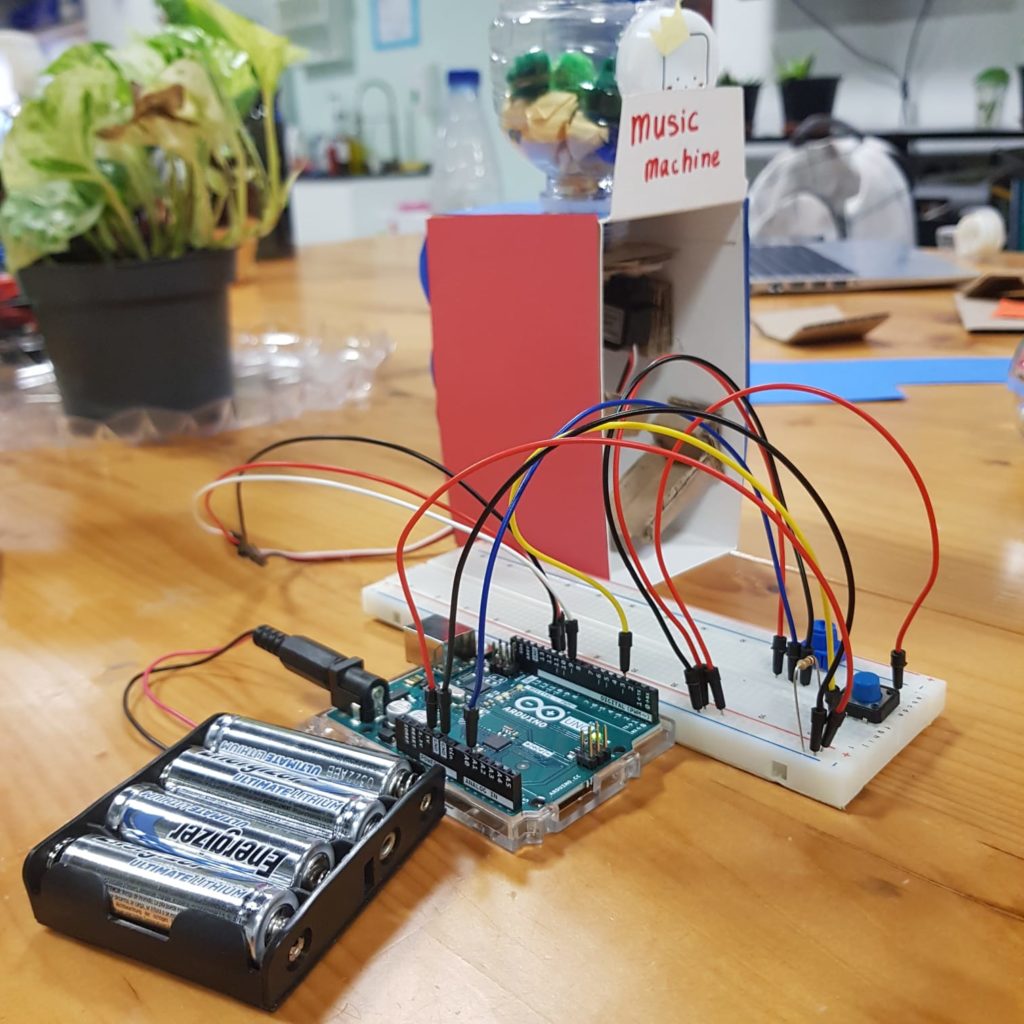
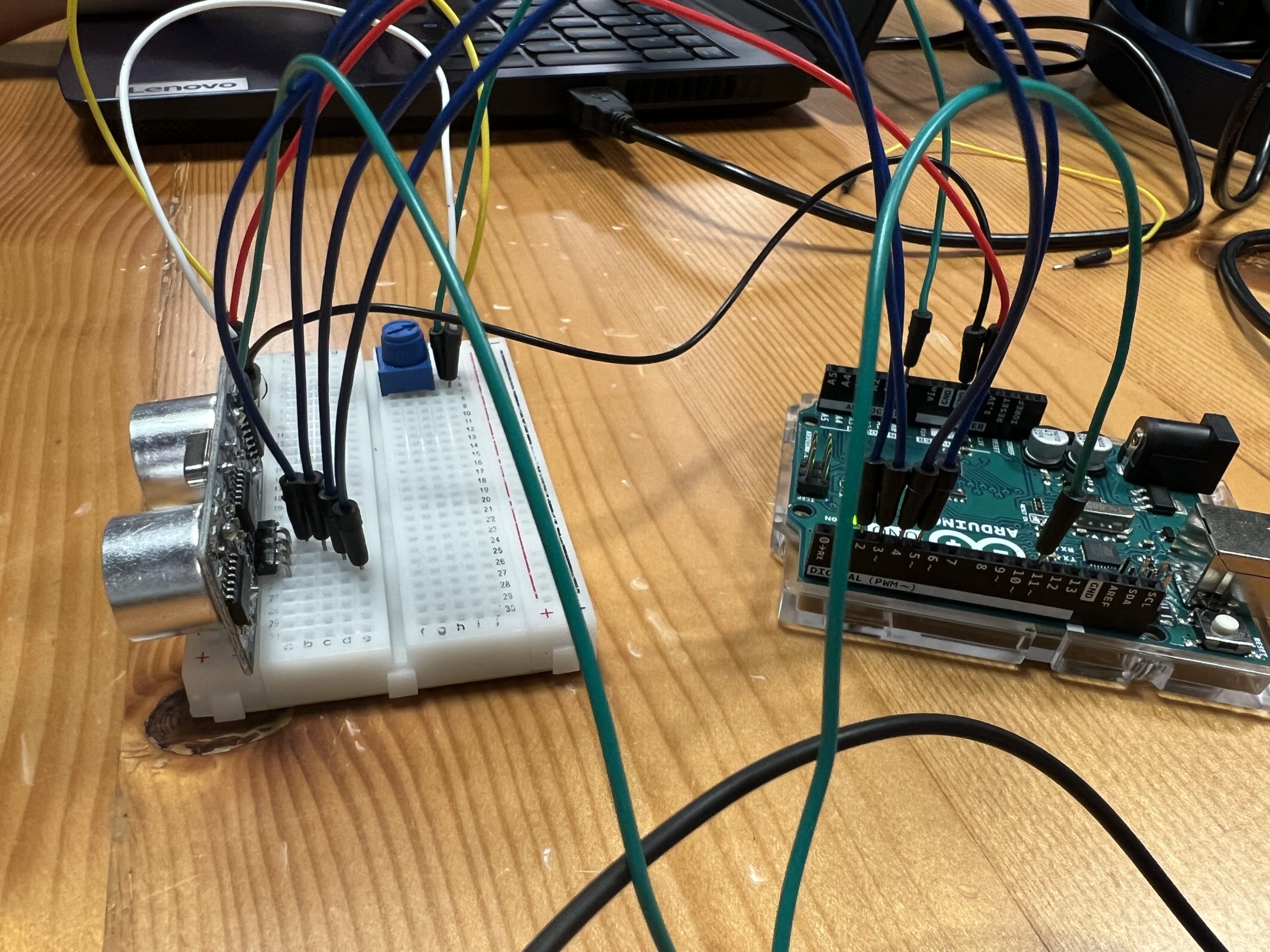
Below is our initial setup:
after hooking it up to the speaker this is what it sounded like:
However, we were still missing a key feature of the assignment which was a button to control the sound output. For that, we used the following simple line of code to detect whether the signal output from the switch was HIGH or not:
buttonState = digitalRead(buttonPin);
  if (buttonState == HIGH)
If this statement was held true, it would continue the loop that would initialize the ultrasonic distance sensor and then output a sound signal depending on the position of the hands.
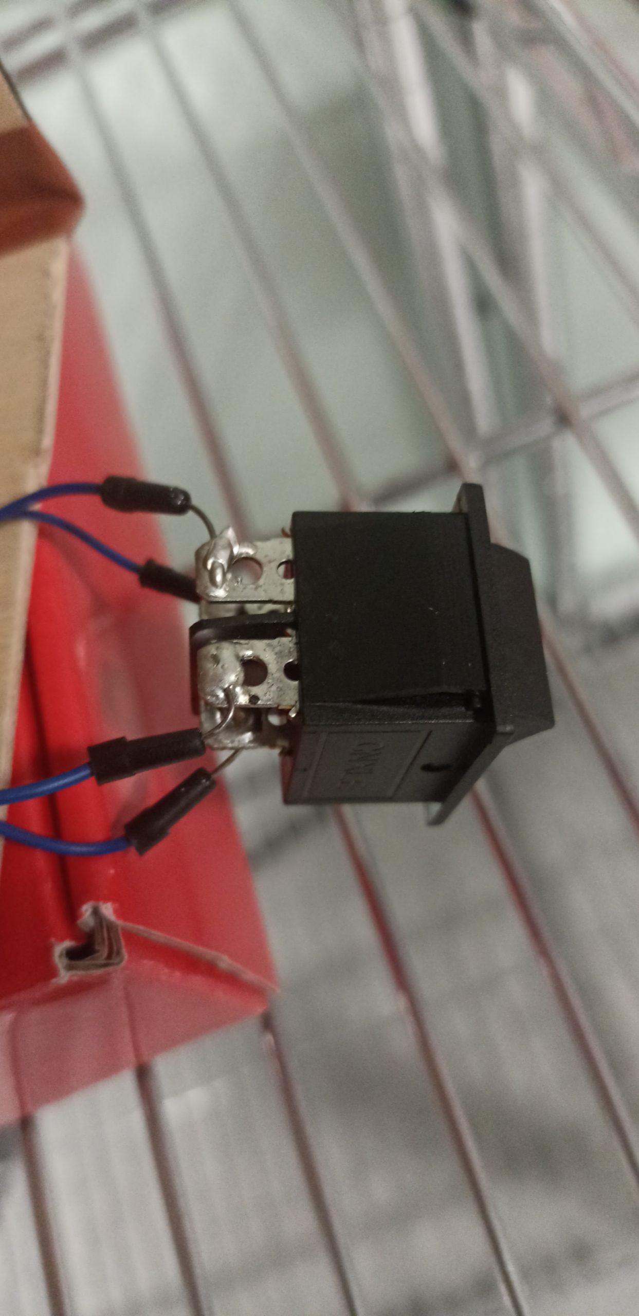
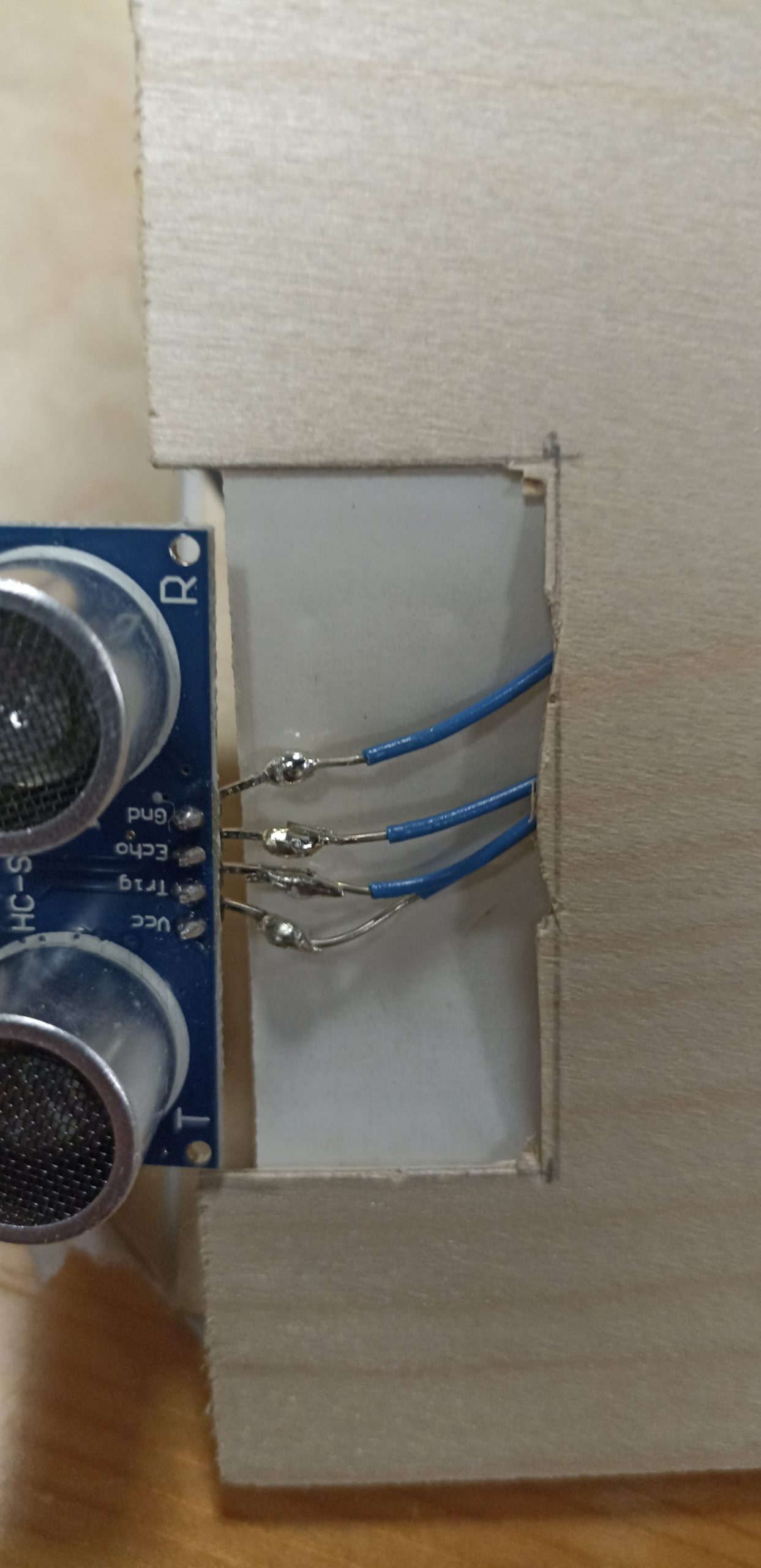
To connect the wires to the button and the ultrasonic distance sensor we had to solder the wires to ensure a strong and secure connection:
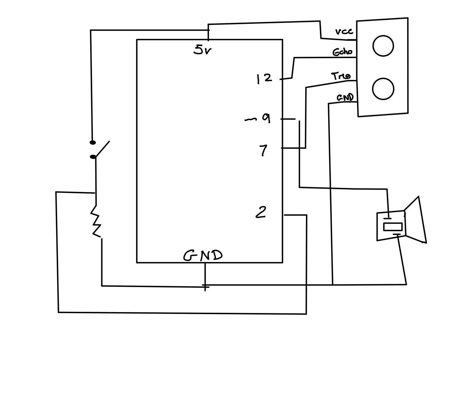
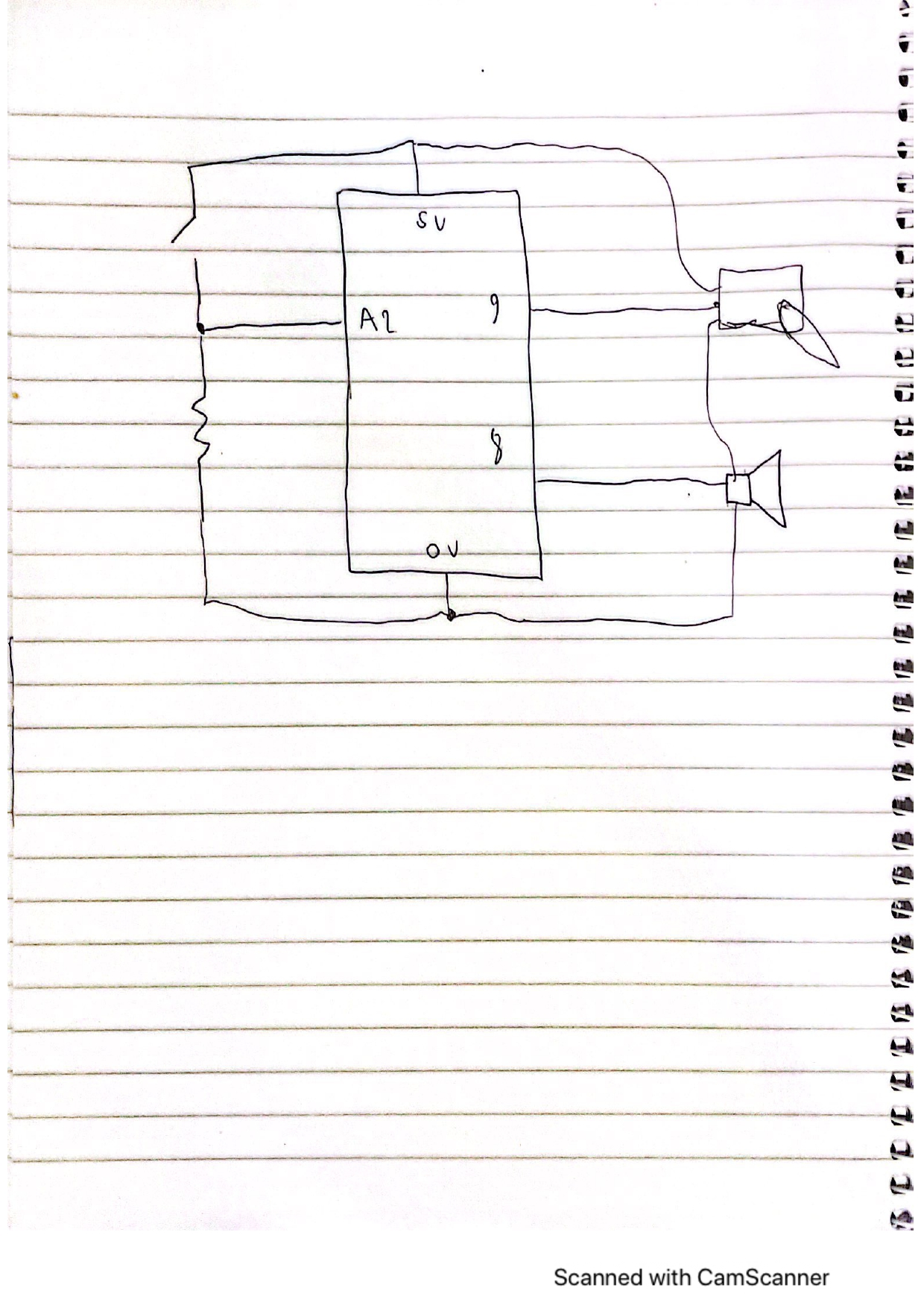
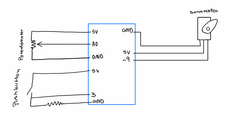
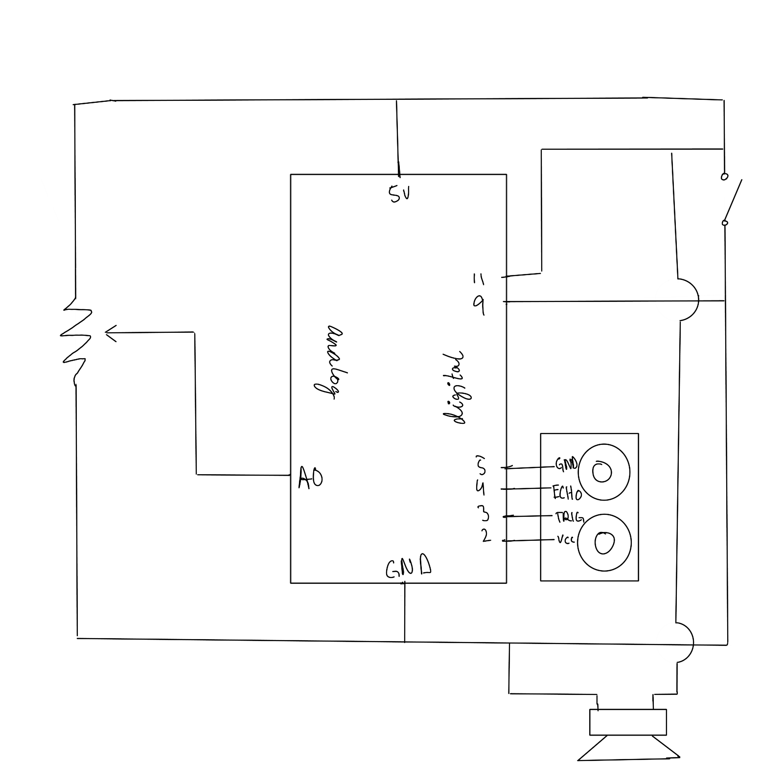
The circuit diagram of the final circuit:
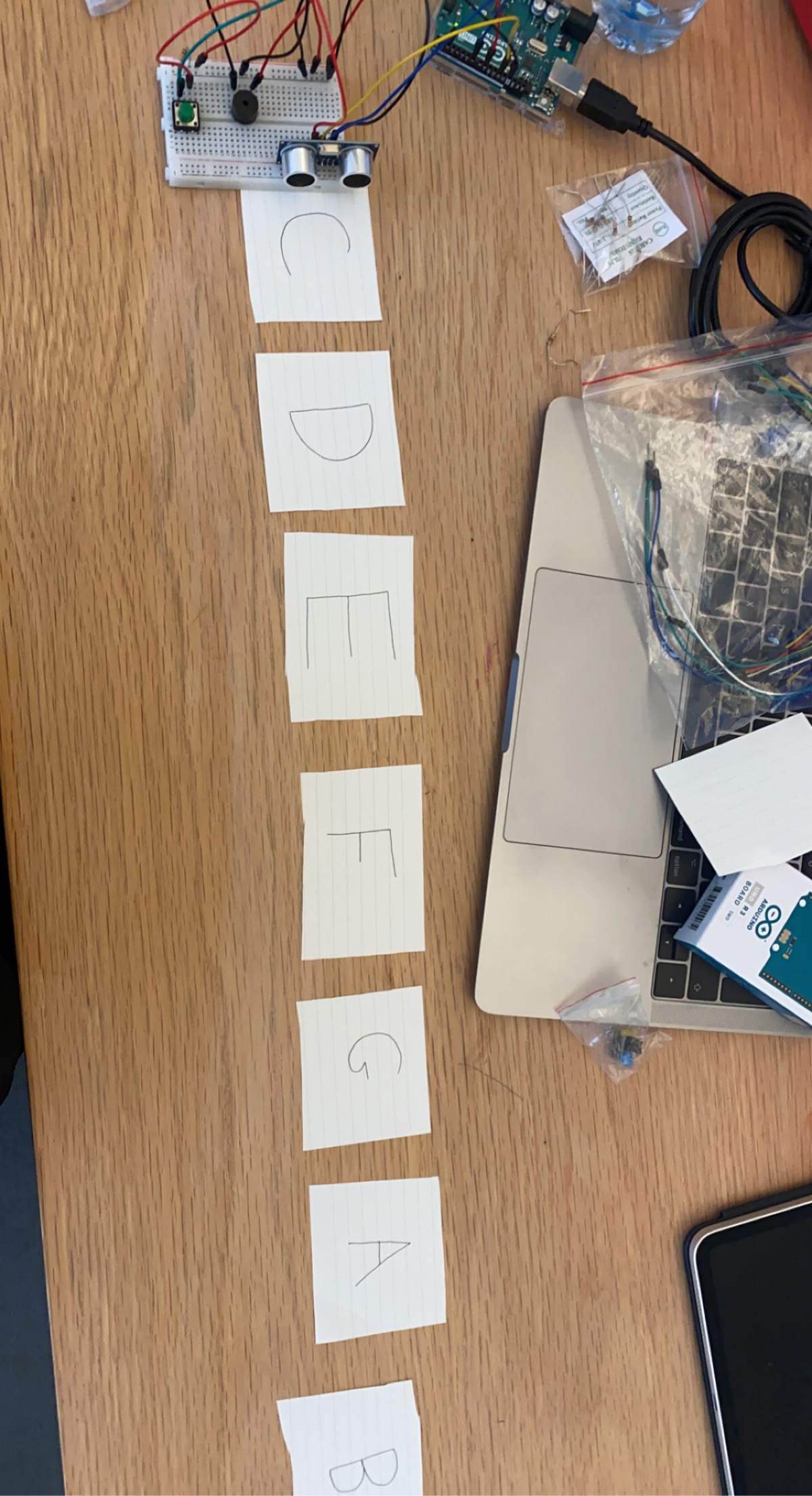
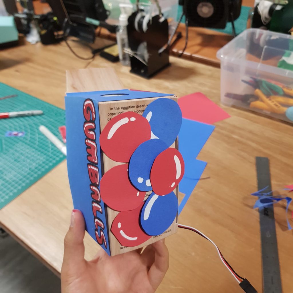
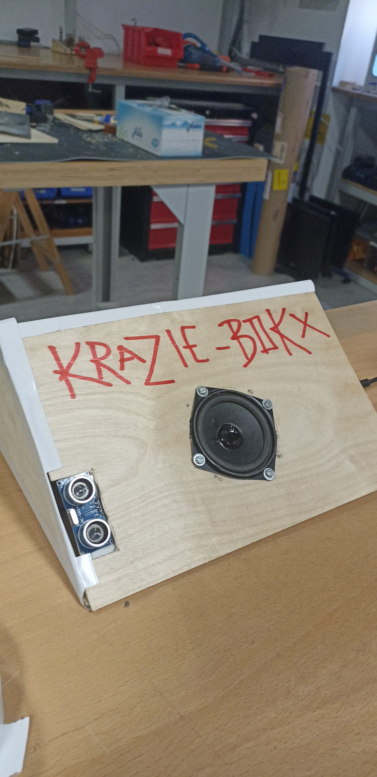
Final project:
The look of the final project assembled: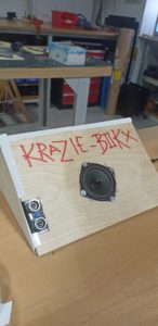
Reflection and Difficulties:
This project was a lot of fun for both of us. We both learned some important information about using distance sensors and the inbuilt functionality of Arduino IDE that helps make a lot of information processing very easy as a programmer. We also had to solder which was a new experience and allowed us to gain important hands-on knowledge in building practical circuits. Some of the difficulties we faced included code optimization and building usable circuits.
We also learned the importance of top-down development in building circuits; we used a multitude of resources and examples and our own creativity to create circuits with a lot of unnecessary parts. After tinkering and experimenting we were able to streamline not only our circuit to be as simple as functionally possible while losing no part of the usability.
With complex circuits, we discovered that cable management was very important and some of our components were regularly shorting. to reduce this effect we used tape and insulators but it was still far from perfect. Additionally, we could have used heat-shrinking insulating wraps to create better insulation.
Also, we had trouble using the buttons available in the kit because they were pushing buttons and not permanent switches. The fix was super easy thankfully and only required replacement parts that we found in the lab. The button initially would turn the whole board off but that was only because we hooked up the wires the wrong way.