Exercise 1
Make something that uses only one sensor on Arduino and makes the ellipse in p5 move on the horizontal axis, in the middle of the screen, and nothing on Arduino is controlled by p5.js.
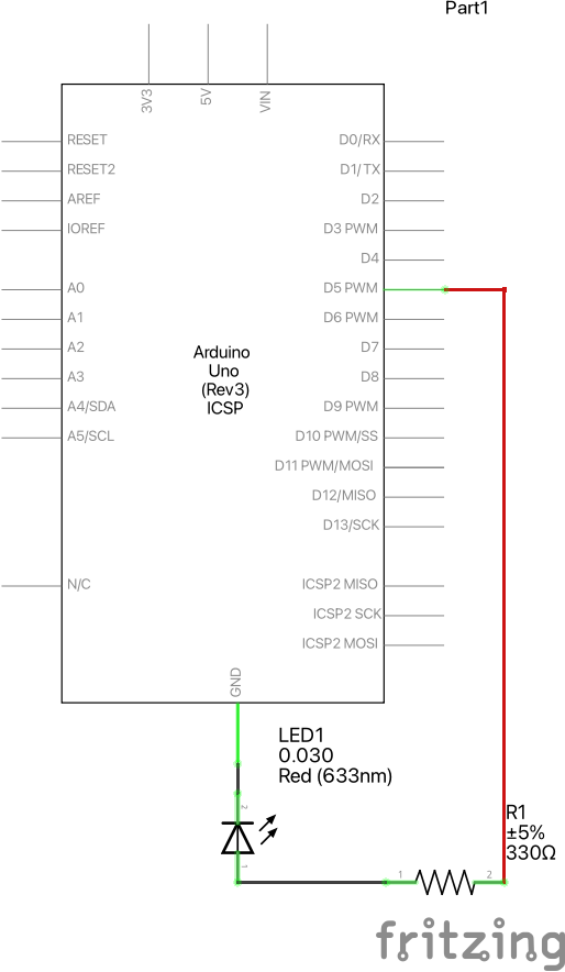
For this exercise, a tiny circle’s x-coordinates are controlled by the reading from a potentiometer. The Arduino sends data to p5.js and the data received is used to control the movement of the circle on the canvas.
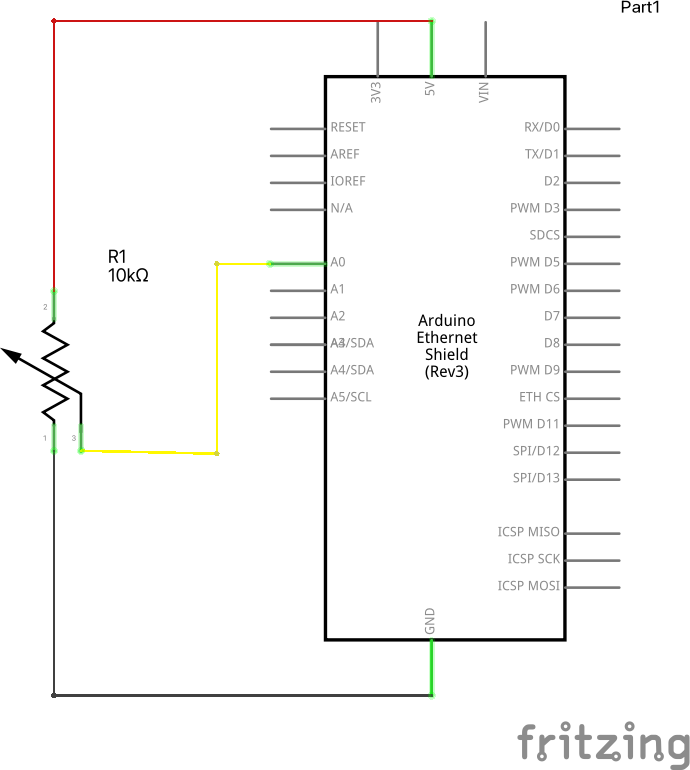
The schematics of the circuit are as below.
Two separate files behind this exercise are:
p5.js Code:
// Global variables added
let h = 1000;          // Canvas height
let w = 1000;          // Canvas width
let ellipse_height = 50;
let ellipse_width = 50;


// variable to hold an instance of the p5.webserial library:
const serial = new p5.WebSerial();

// HTML button object:
let portButton;
let inData;                   // for incoming serial data
let outByte = 0;              // for outgoing data


function setup()
{
  createCanvas(w, h);          // make the canvas

  // check to see if serial is available:
  if (!navigator.serial) {
    alert("WebSerial is not supported in this browser. Try Chrome or MS Edge.");
  }
  // if serial is available, add connect/disconnect listeners:
  navigator.serial.addEventListener("connect", portConnect);
  navigator.serial.addEventListener("disconnect", portDisconnect);
  // check for any ports that are available:
  serial.getPorts();
  // if there's no port chosen, choose one:
  serial.on("noport", makePortButton);
  // open whatever port is available:
  serial.on("portavailable", openPort);
  // handle serial errors:
  serial.on("requesterror", portError);
  // handle any incoming serial data:
  serial.on("data", serialEvent);
  serial.on("close", makePortButton);
}


function draw()
{

  background(50);
  fill(255);

  textSize(25);
  text("Raw sensor value: " + inData, 30, 50);


  // ------------------ Ellipse Values ----------------
  let max_pot_reading = 255;
  let map_error_corr = ellipse_width/2;

  // X-coordinate is scaled based on the readings from potentiometer
  let scaled_x_pos = map(inData, 0, max_pot_reading, map_error_corr, (w-map_error_corr));


  // Draw ellipse using the values determined above
  draw_ellipse(scaled_x_pos, (h/2 - map_error_corr), ellipse_height, ellipse_width);


  // Text Display on the right side of the canvas
  let rounded_x_pos = round(scaled_x_pos, 2);          // Data rounded upto 2 decimal places
  textSize(25);
  fill("white");
  text("Scaled X-position: " + rounded_x_pos, (w/2 + 150), 50);

}


// Function to draw an ellipse
// Aruguments; (x, y) coordinates && width and height
function draw_ellipse(x, y, w_, h_)
{
  fill("red");
  ellipse(x, y, w_, h_);
}


// if there's no port selected,
// make a port select button appear:
function makePortButton() {
  // create and position a port chooser button:
  portButton = createButton("choose port");
  portButton.position(10, 10);
  // give the port button a mousepressed handler:
  portButton.mousePressed(choosePort);
}

// make the port selector window appear:
function choosePort() {
  if (portButton) portButton.show();
  serial.requestPort();
}

// open the selected port, and make the port
// button invisible:
function openPort() {
  // wait for the serial.open promise to return,
  // then call the initiateSerial function
  serial.open().then(initiateSerial);

  // once the port opens, let the user know:
  function initiateSerial() {
    console.log("port open");
  }
  // hide the port button once a port is chosen:
  if (portButton) portButton.hide();
}

// pop up an alert if there's a port error:
function portError(err) {
  alert("Serial port error: " + err);
}
// read any incoming data as a string
// (assumes a newline at the end of it):
function serialEvent() {
  inData = Number(serial.read());
  console.log(inData);
}

// try to connect if a new serial port
// gets added (i.e. plugged in via USB):
function portConnect() {
  console.log("port connected");
  serial.getPorts();
}

// if a port is disconnected:
function portDisconnect() {
  serial.close();
  console.log("port disconnected");
}

function closePort() {
  serial.close();
}
Arduino Code:
int potPin = A0;

void setup()
{
  Serial.begin(9600); // initialize serial communications
}

void loop()
{
  // read the input pin:
  int pot_read = analogRead(potPin);

  // remap the pot value to fit in 1 byte:
  int mappedPot = map(pot_read, 0, 1023, 0, 255);

  // print it out the serial port:
  Serial.write(mappedPot);

  // slight delay to stabilize the ADC:
  delay(1);

  // Delay to send 10 times per second
  delay(100);
}
Use this link to access the p5.js editor.
Exercise 2
Make something that controls the LED brightness from p5.js.
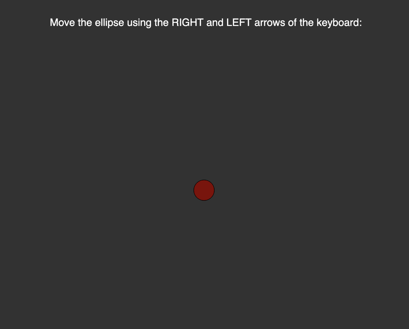
In this exercise, keyboard arrows can be used to control the movement of a ball on the screen — X-coordinates of the ball. As the ball is moved across the screen, its gradient changes (darker red means less bright LED, whereas brighter/ true red means brighter LED). In this exercise, when the ball is at the leftmost part of the canvas, the LED attached emits less light and vice versa.
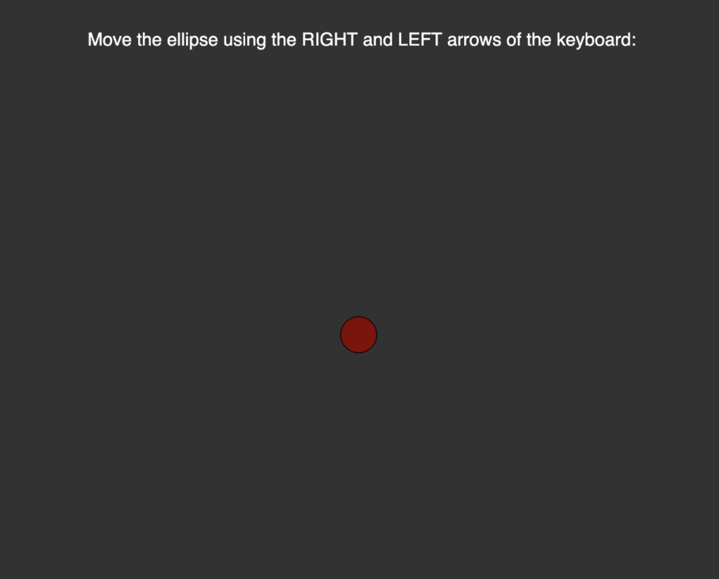
Here, the ball is located in the middle of the screen and is moderately red. As it is moved to different sides using the arrows, its color changes accordingly — in return, the LED’s brightness changes as well.
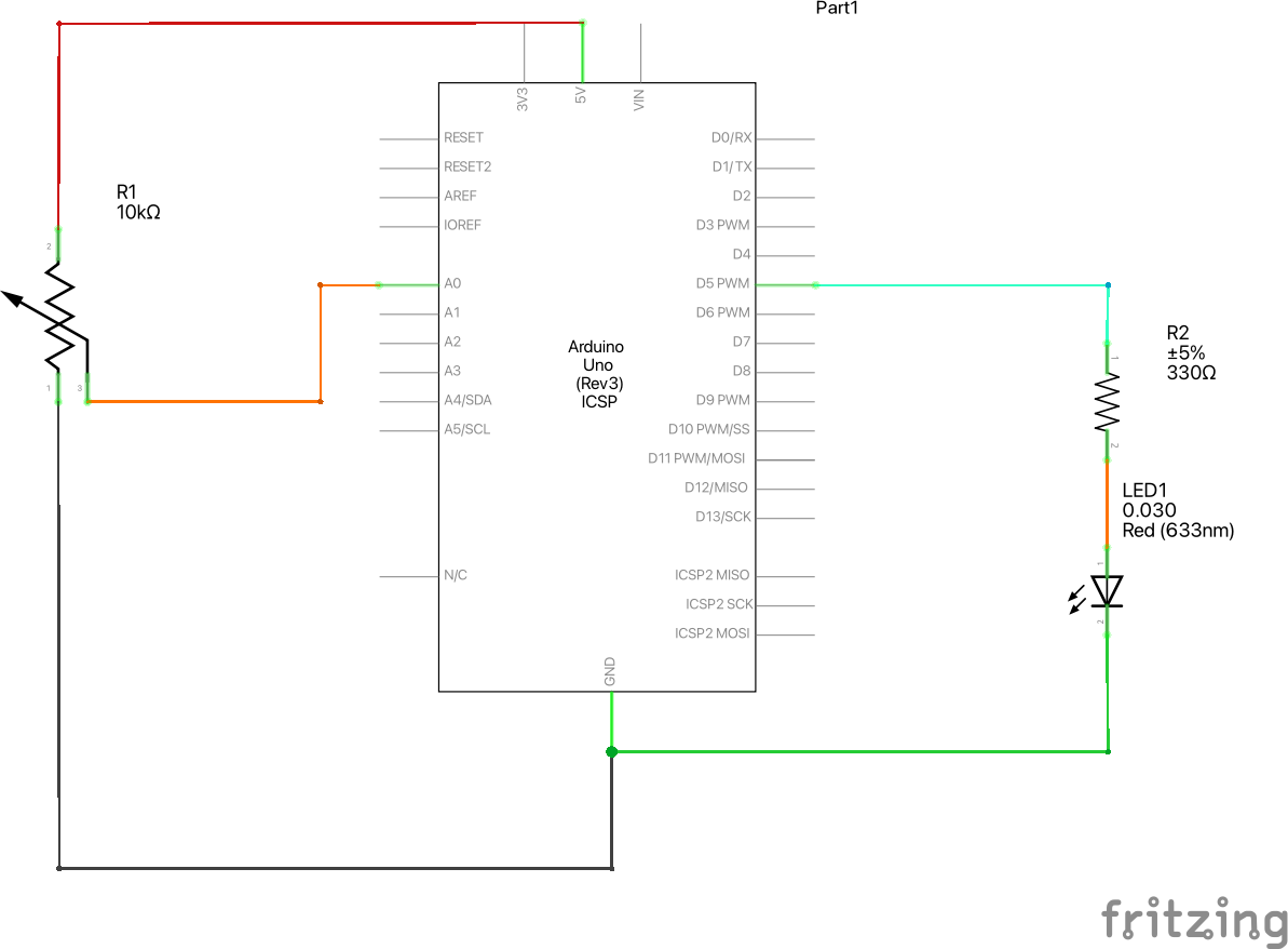
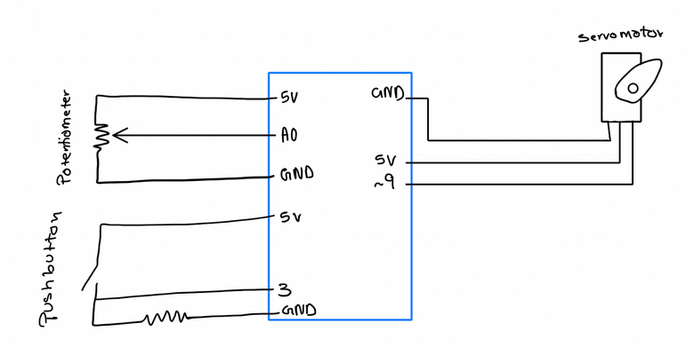
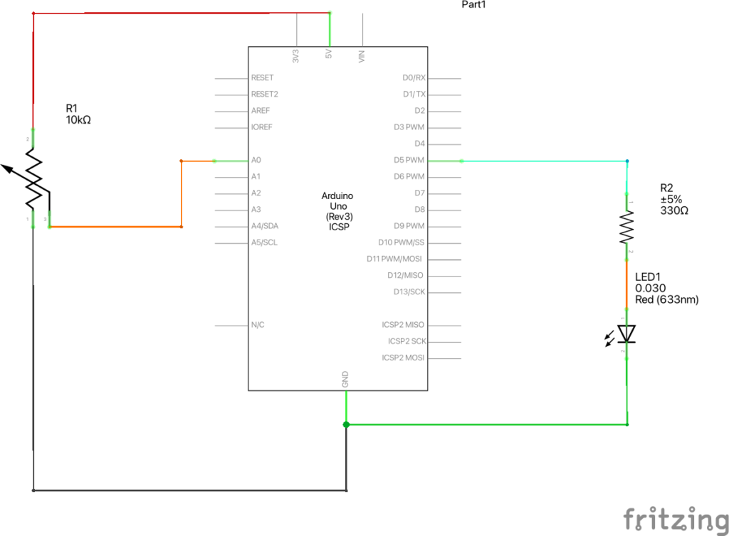
The schematics of the circuit are as below.
Two separate files behind this exercise are:
p5.js Code:
// Global variables added
let h = 1000;          // Canvas height
let w = 1000;          // Canvas width
let ellipse_h = 50;
let ellipse_w = 50;
let ellipse_x = w/2;
let ellipse_y = h/2;
let ellipse_vx = 0;
let error_corr = (ellipse_w/2);
let ellipse_vel = 3;


// variable to hold an instance of the p5.webserial library:
const serial = new p5.WebSerial();

// HTML button object:
let portButton;
let inData;                   // for incoming serial data
let outByte = 0;              // for outgoing data


function setup()
{

  createCanvas(w, h);          // make the canvas


  // check to see if serial is available:
  if (!navigator.serial)
  {
    alert("WebSerial is not supported in this browser. Try Chrome or MS Edge.");
  }

  // if serial is available, add connect/disconnect listeners:
  navigator.serial.addEventListener("connect", portConnect);
  navigator.serial.addEventListener("disconnect", portDisconnect);

  // check for any ports that are available:
  serial.getPorts();

  // if there's no port chosen, choose one:
  serial.on("noport", makePortButton);

  // open whatever port is available:
  serial.on("portavailable", openPort);

  // handle serial errors:
  serial.on("requesterror", portError);

  // handle any incoming serial data:
  serial.on("data", serialEvent);
  serial.on("close", makePortButton);


}

function draw() {

  background(50);
  displayText();

  let color_gradient = map(ellipse_x, 0, (w - error_corr), 0, 255);
  let color_ = color(color_gradient, 0, 0);
  draw_ellipse(ellipse_x, ellipse_y, ellipse_w, ellipse_h, color_);
  pos_check();
  pos_update();

}


function displayText()
{
  textSize(25);
  fill("white");
  text("Move the ellipse using the RIGHT and LEFT arrows of the keyboard: ", error_corr * 5, h/2 - 400);
}


// Function to draw an ellipse
// Aruguments; (x, y) coordinates && width and height
function draw_ellipse(x, y, w_, h_, color)
{
  fill(color);
  ellipse(x, y, w_, h_);
}


function pos_check()
{
  if ((ellipse_x - error_corr) <= 0)
    ellipse_x = error_corr;
  else if (ellipse_x >= (w - error_corr))
    ellipse_x = w - error_corr;
}

function pos_update()
{
    ellipse_x += ellipse_vx;
}


function keyPressed()
{
  // If RIGHT_ARROW is pressed, the character needs to move right, so set horizontal velocity using global var
  if (keyCode === RIGHT_ARROW)
  {
    ellipse_vx = ellipse_vel;

  }

  // If LEFT_ARROW is pressed, the character needs to move left, so set horizontal velocity using global var
  if (keyCode === LEFT_ARROW)
  {
    ellipse_vx = -ellipse_vel;
  }

  let serial_val_ = (map(ellipse_x, 0, (w - error_corr), 0, 255));
  serial.write(serial_val_);
  // print("Serial " + serial_val_);


}


// Function that helps to move the ellipse one step at a time
function keyReleased()
{
  // After RIGHT or LEFT arrow is released, set horizontal velocity to 0
  if (keyCode === RIGHT_ARROW || keyCode === LEFT_ARROW)
  {
    ellipse_vx = 0;
  }

}


// if there's no port selected,
// make a port select button appear:
function makePortButton() {
  // create and position a port chooser button:
  portButton = createButton("choose port");
  portButton.position(10, 10);
  // give the port button a mousepressed handler:
  portButton.mousePressed(choosePort);
}


// make the port selector window appear:
function choosePort() {
  if (portButton) portButton.show();
  serial.requestPort();
}


// open the selected port, and make the port
// button invisible:
function openPort() {
  // wait for the serial.open promise to return,
  // then call the initiateSerial function
  serial.open().then(initiateSerial);

  // once the port opens, let the user know:
  function initiateSerial() {
    console.log("port open");
  }
  // hide the port button once a port is chosen:
  if (portButton) portButton.hide();
}


// pop up an alert if there's a port error:
function portError(err) {
  alert("Serial port error: " + err);
}


// read any incoming data as a string
// (assumes a newline at the end of it):
function serialEvent() {
  inData = Number(serial.read());
  console.log(inData);

  // serial.write(ellipse_x);
}


// try to connect if a new serial port
// gets added (i.e. plugged in via USB):
function portConnect() {
  console.log("port connected");
  serial.getPorts();
}


// if a port is disconnected:
function portDisconnect() {
  serial.close();
  console.log("port disconnected");
}


function closePort() {
  serial.close();
}
Arduino Code:
int ledPin = 5;
int serialRead = 0;

void setup()
{
  Serial.begin(9600);
  pinMode(ledPin, OUTPUT);
}

void loop()
{
  while (Serial.available() > 0)
  {
    serialRead = Serial.read();
    analogWrite(ledPin, serialRead);
  }
}
Use this link to access the p5.js editor.
Exercise 3
Make it so every time the ball bounces one led lights up and then turns off, and you can control the wind from one analog sensor.
For this exercise, a potentiometer has been used to read analog data from the Arduino board. The data collected is mapped to a scale of user-set-value (currently set to 3). So, based on this value, wind speed is determined. Additionally, whenever the ball bounces, a LED flickers.
A few other improvizations have been implemented in addition to the wind-gravity-file given:
- A background image has been uploaded to replicate a visual of a ball moving across a canvas.
- The user can determine if the ball remains within the canvas or not. It is facilitated by a global variable at the beginning of the program.
- The user can see the statistics related to the ball on the screen.
The schematics of the circuit are as below.
Two separate files behind this exercise are:
p5.js Code:
// USER CONTROl - The user can decide if the ball can stay within the canvas or can go beyond it
// 'y' = The ball can travel beyond right/ left border
// 'n' = The ball should stay within the border
let beyondBorder = "n";
let max_wind_vel = 3;                // Maximum Wind Speed
let ledBrightness = 255;


// Misc Global Variables
let canvas_w = 800;
let canvas_h = 800;

// Global Variables for gravity wind
let velocity;
let gravity;
let position_;
let acceleration;
let wind;
let drag = 0.99;
let mass = 50;
let error_corr = 5;                  // Variable that fixes ball dimension
let scaled_wind;                     // Variable used to track wind speed and direction

// Global Variables for Serial Communication
// variable to hold an instance of the p5.webserial library:
const serial = new p5.WebSerial();


// HTML button object:
let portButton;
let inData;                   // for incoming serial data
let temp_inData;
let outByte = 0;              // for outgoing data

let statusOnOff = 0;          // LED Blinking Effect
let bg_image;                 // Image variable for background image


// Loading the background image
function preload()
{
  bg_img = loadImage("image/bg_dash.png");
}


function setup()
{
  // Initial program setup
  imageMode(CORNER);
  createCanvas(canvas_w, canvas_h);
  noFill();
  position_ = createVector(width/2, 0);
  velocity = createVector(0,0);
  acceleration = createVector(0,0);
  gravity = createVector(0, 0.5*mass);
  wind = createVector(0,0);


  // check to see if serial is available:
  if (!navigator.serial)
  {
    alert("WebSerial is not supported in this browser. Try Chrome or MS Edge.");
  }

  // if serial is available, add connect/disconnect listeners:
  navigator.serial.addEventListener("connect", portConnect);
  navigator.serial.addEventListener("disconnect", portDisconnect);

  // check for any ports that are available:
  serial.getPorts();

  // if there's no port chosen, choose one:
  serial.on("noport", makePortButton);

  // open whatever port is available:
  serial.on("portavailable", openPort);

  // handle serial errors:
  serial.on("requesterror", portError);

  // handle any incoming serial data:
  serial.on("data", serialEvent);
  serial.on("close", makePortButton);
}


function draw()
{
  // background(255);
  image(bg_img, 0, 0, canvas_w, canvas_h);
  display_text();

  // Conditional that disables/ enables the functionality to keep the ball within the canvas
  if (beyondBorder == "n" || beyondBorder == "N" || beyondBorder == "NO" || beyondBorder == "no" || beyondBorder == "No")
    pos_check();

  // Initial Setup
  applyForce(wind);
  applyForce(gravity);
  velocity.add(acceleration);
  velocity.mult(drag);
  position_.add(velocity);
  acceleration.mult(0);
  fill(247, 180, 5);
  ellipse(position_.x,position_.y,mass,mass);

  if (position_.y > height - mass/2)
  {
      velocity.y *= -0.9;  // A little dampening when hitting the bottom
      position_.y = height - mass/2;

  }


  // LED SETUP
  if (position_.y > height - mass/2 - mass)
  {
    if (velocity.y > 1)
    {
      serial.write(ledBrightness);
    }
  }


  // Wind Setup
  let max_pot_reading = 255;
  scaled_wind = map(inData, 0, max_pot_reading, -max_wind_vel, max_wind_vel);

  print("X Pos: ", position_.x);
  // print("Pot Reading: ", inData);
  // print("Scaled: ", scaled_data);

  wind.x = scaled_wind;
  // wind.y = scaled_data;

}


// Replicates the ball's movement
function applyForce(force)
{
  // Newton's 2nd law: F = M * A
  // or A = F / M
  let f = p5.Vector.div(force, mass);
  acceleration.add(f);
}


// Keyboard Control
function keyPressed()
{
  if (keyCode==LEFT_ARROW){
    wind.x=-1;
  }
  if (keyCode==RIGHT_ARROW){
    wind.x=1;
  }
  if (key==' '){
    mass=random(15,80);
    position_.y=-mass;
    velocity.mult(0);
  }
}


// Function that checks if the ball is within the canvas or not
// It restricts the ball from exiting the canvas
// Called in draw() function
function pos_check()
{
  // error_corr helps to keep ball within the frame.
  // Without it, some portion of the ball disappears into the walls.
  // Here, 2.5 is a special value that avoids glitchy effect when wind direction is changed
  if ((position_.x - mass/2) < 2.5)
    position_.x = mass/2 + error_corr;

  else if (position_.x >= (canvas_w - mass/2) - 2.5)
    position_.x = canvas_w - mass/2 - error_corr;
}


// Function that displays information on the canvas
function display_text()
{
  textSize(17);
  fill("white");

  let x_ = round(position_.x, 2) - mass/2 + 1;
  let y_ = canvas_h - (round(position_.y, 2) - mass/2 + mass);

  text("X-position = " + round(x_), (canvas_w - 200), 50);
  text("Y-position = " + round(y_), (canvas_w - 200), 70);
  text("Wind-Speed = " + round(scaled_wind, 3), (canvas_w - 200), 90);

}


// if there's no port selected,
// make a port select button appear:
function makePortButton()
{
  // create and position_ a port chooser button:
  portButton = createButton("choose port");
  portButton.position(10, 10);
  // give the port button a mousepressed handler:
  portButton.mousePressed(choosePort);
}


// make the port selector window appear:
function choosePort()
{
  if (portButton) portButton.show();
  serial.requestPort();
}


// open the selected port, and make the port
// button invisible:
function openPort()
{
  // wait for the serial.open promise to return,
  // then call the initiateSerial function
  serial.open().then(initiateSerial);

  // once the port opens, let the user know:
  function initiateSerial() {
    console.log("port open");
  }
  // hide the port button once a port is chosen:
  if (portButton) portButton.hide();
}


// pop up an alert if there's a port error:
function portError(err)
{
  alert("Serial port error: " + err);
}


// read any incoming data as a string
// (assumes a newline at the end of it):
function serialEvent()
{
  inData = Number(serial.read());
  console.log(inData);

  serial.write(statusOnOff);          // Blinking Effect
}


// try to connect if a new serial port
// gets added (i.e. plugged in via USB):
function portConnect()
{
  console.log("port connected");
  serial.getPorts();
}


// if a port is disconnected:
function portDisconnect()
{
  serial.close();
  console.log("port disconnected");
}


function closePort()
{
  serial.close();
Arduino Code:
// Global variables
int ledPin = 5;
int potPin = A0;
int serialRead = 0;

void setup()
{
  Serial.begin(9600);
  pinMode(ledPin, OUTPUT);          // Set the LED pin
}

void loop()
{
  // Reading input from the potentiometer
  while (Serial.available() > 0)
  {
    serialRead = Serial.read();
    analogWrite(ledPin, serialRead);
  }

  // read the input pin:
  int pot_read = analogRead(potPin);

  // remap the pot value to fit in 1 byte:
  int mappedPot = map(pot_read, 0, 1023, 0, 255);

  // print it out the serial port:
  Serial.write(mappedPot);

  // slight delay to stabilize the ADC:
  delay(1);

  // Delay to send 10 times per second
  delay(100);
}
Use this link to access the p5.js editor.
A video demonstration of this exercise can be found here:
View the entire project on GitHub.