[Assignment 9] Police Light

Concept

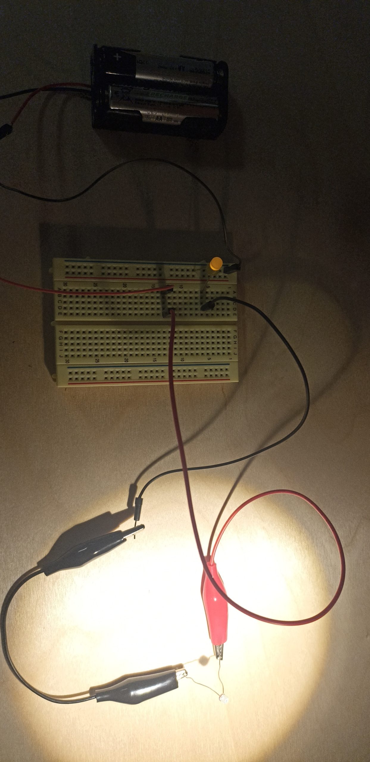
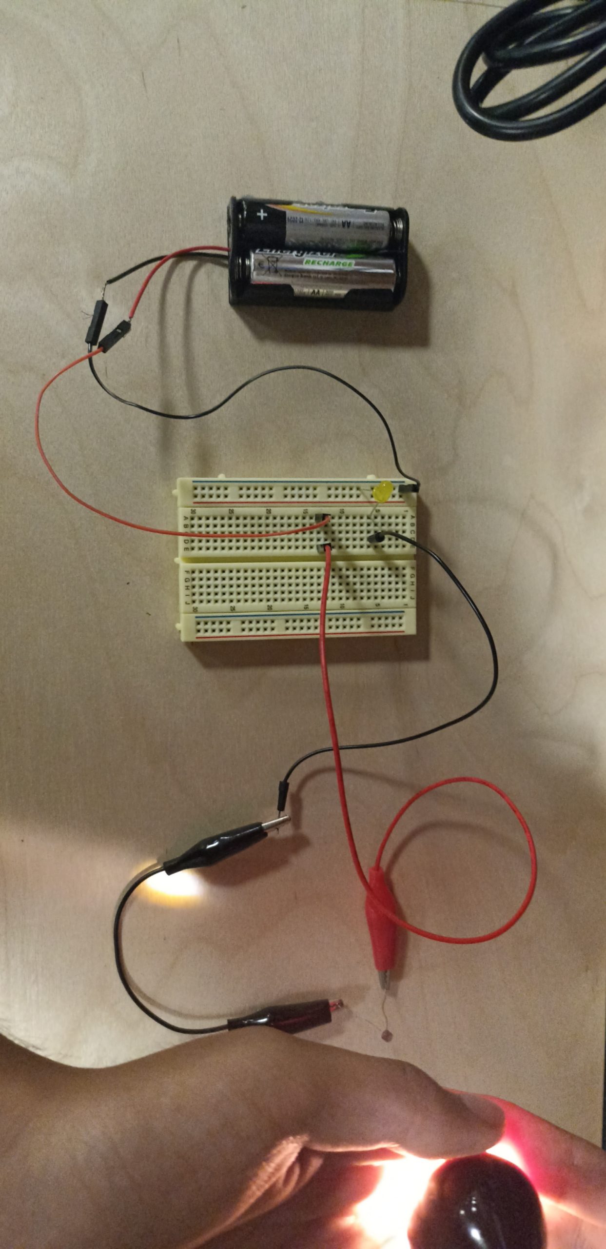
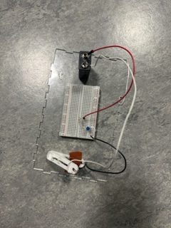
For this assignment, I made a police light using two LEDs, a button, and a potentiometer. When the button is pressed once, the blue LED turns on; when the button is pressed twice, the blue LED turns off and the red LED turns on; when the button is pressed three times, the two LEDs turn on and off alternatively. Using the potentiometer, the user can also control how fast the two LEDs will turn on and off.

Codes

As mentioned above, this police light has 3 modes: two single-light modes and alternating lights modes. This mode (0, 1, and 2) will change whenever the user presses the button. Since Arduino will read a single button press as a series of multiple “1s,” I used millis() to make sure Arduino reads only a single 1 for every 200ms. This means Arduino will ignore any 1s that come after the first 1 within 200ms. When 1 is read, the mode will increase by 1 and back to 0 after 2. Variable blueLED is a boolean that is used to keep track of which single LED to turn on and off.

if (currentTime == 0 || millis() - currentTime > 200) {
    if (switchVal) {
      mode = ++mode % 3;
      if (mode != 2) blueLED = !blueLED; 
    }
    currentTime = millis();
  }

Then, the program will turn LEDs on and off according to the current mode. For mode 0 and 1:

if (mode != 2) {
  if (blueLED) {
    digitalWrite(13, HIGH);
    digitalWrite(12, LOW);
  } else {
    digitalWrite(13, LOW);
    digitalWrite(12, HIGH);
  }
}

For mode 2, two LEDs turns on and off alternatively. I could have used delay() to achieve this effect, but I decided to not use such function because Arduino cannot read any other sensor data at the same time. Instead, I used millis() to do this.  pVal is a analog reading of potentiometer and the input was mapped to a value between 0 and 800. LEDs will turn on and off for every pVal ms.

int pVal = map(analogRead(A0), 1023, 0, 0, 800);

else {
  if (millis() - ledTime > pVal) {
    if (ledOnOff) {
      digitalWrite(13, HIGH);
      digitalWrite(12, LOW);
    } else {
      digitalWrite(13, LOW);
      digitalWrite(12, HIGH);
    }

    ledTime = millis();
    ledOnOff = !ledOnOff;
  }
}

Future Improvements

This project turned out to be better than I first expected. I am very satisfied about the fact that the button is functional even when LEDs are alternatively lighting up by not using delay(). For future improvements, I may be able to add more complex patterns to the LEDs, which seems challenging because no delay()s can be used. Additionally, adding piezo speaker included in the kit will make this police light more interesting and realistic.

Aisha – Assignment 5: Switch

For my assignment, I decided I wanted to create something that was fun and could keep me busy for quite some time. Thus, I decided to create a ball-tossing game where the ball has to enter the cup in order for the LED switch to light up. I used the standard materials within the Arduino kit (wires, resistor, LED light) as well as a small foam cup, a silicon ball wrapped in aluminum, and tape.

Initially, I wanted to have the wires taped at the bottom of the cup. After testing out whether the aluminum ball would light up the LED, I realized it wasn’t going to work and instead made holes in the side of the cup for the wires to fit through and sort of catch the ball when it fell (with the help of tape to keep the wires steady).

Images:

Wire going into the side of the cup
Empty Cup
Cup with the ball inside

Video:

Future Improvements:

  • Something that I wanted to do but couldn’t figure out was to add another LED light for a sort of backboard and if the ball hits the background the other LED will light up so I think it would be really to do that.
  • It would also be cool to add more cups assigned to different lights.
  • Material-wise, I think using a more stable and rigid cup would be useful as it sometimes does move if I hit and miss it. Furthermore, I could add a piece of cardboard or paper in the bottom of the cup to make the wires stable and rigid as I had problems (which I eventually fixed after finding the right angle and using tape on the outside of the cup) where the piece of aluminum wouldn’t touch both wires thus not lighting up the LED.


Assignment 5: Quirky Circuit

Concept:

For my assignment, I wanted to make something unique but also practical. The initial idea I had outlined was a switch that did not exclusively need human manipulation to work and could be tweaked to work automatically. My first thought was a circuit involving a photo sensor.

Brainstorming: 

In class, we talked about photoresistors on Tuesday and that gave me the idea to build a circuit with a photoresistor. The dynamic resistivity of these special devices allowed them to ‘open’ and ‘close’ the circuit depending upon the light conditions. So, I came up with the idea of connecting the photoresistor in a circuit so that other parts of the circuit (in my case an LED) would turn on when there was adequate light shining on the photoresistor (the resistance would be very low in this case) and then turn off once the light level reduced (causing the resistance of the photoresistor to shoot up to some absurdly high level). This type of circuit could be used to automate street lights (with a reversed mechanism obviously) to turn off lights during the day and turn them on in the evening.

Implementation:

The photoresistor that I used:

LED on in adequate light:

LED turned off in lower light conditions:


Reflection:

During my experiment, I realized the circuit was not going to be perfect in the real world. although theoretically, in zero light conditions, the resistivity in the photoresistor would approach a near-infinite level, however not only is that impossible in real life, there was ambient light all around the IM lab where I was doing the experiment. It led to the LED being faintly lit even when the circuit was supposed to be ‘open’.

In the future, I will have to link the photoresistor to perhaps a mechanical device like a servo that can physically open the circuit or close it depending on the current passing through the wire.

Assignment 5: Creative Switch

The brainstorming process took longer than the creating of the switch. It’s really hard to think of a switch that doesn’t require using your hands at all. I kept thinking of ideas that indirectly used my hands, which I felt like is still considered a switch that uses my hands. For example, one idea I had was opening my water bottle will be switch the light on, but this meant using my hand to push the button of my water bottle to open it. Another idea I had was a hair clip, but again it required my hands to put the clip in my hair. I also thought of using earrings, but it was a bit complicated to get the switch connection.

As I was trying to figure out what to do for my switch, I realized that I spend so much time just sitting and tinkering with ideas. So why not create a switch that takes advantage of sitting?

Once I got the idea, the process of creating it didn’t take too long. I found conductive fabric in the IM lab and decided to use it (note: it is surprisingly conductive because I got shocked twice holding the wire and fabric with my bare fingers). I just used tape to tape one end of the wire against the chair and one on my back. It’s kind of ridiculous, but it works! I tried to position it so that the LED lights up only when you sit with your back straight against the chair. So my idea for this switch is to help make your posture better, since I’m guilty of having bad posture as I’m staring at my laptop.

Here is the video of the switch in action:


Codeless LED Switch

Concept: This switch is turned on when the brake pedals are pressed. The simple LED circuit is connected to a clothes pin (the brake pedal), a resistor, and a 9V battery.  I used a breadboard and different materials I found in the lab like wires.
recordedVid

Reflection: I loved working on a hands on project that involved no coding and seeing how we could be creative in so many ways.

Switch Assignment

Concept 

I wanted to create something that is creative and also has some historical influence. so i thought about a bunch of diffrent ideas. and then it clicked like the light bulb that shows up on top of your heads in cartoons. why don’t i use hats? so i decided to do something unique with the old custom of tipping your hat. tipping your hat is used as a symbol of greeting in cultures in the past, some people still use it to this day!

My Circuit 

So i created a simple circuit the allows the LED to turn on when you tip your hat.

IMG_3691

Thing to improve 

SO i really wanted to wear the hat and be able to tip it but unfortunately the wires were too short. i tried to create a bridge with the foil but it kept failing. i also wanted to create a less obvious piece of foil. but overall i am really happy with how it turned out!

Creative Switch

Concept

When I first wanted to create a creative switch using the LED lights and the arduino, I was thinking about applications that would need very long wires and big spaces. Then, I decided to implement a simple creative switch using the simple short wires that I possess. As a result, I started testing out the conductivity of different materials in my room. I realized that the aluminum foil is a good conductor of electricity. Therefore, I decided to use it to come up with an interactive trash can.


I used the aluminum foil with the wires and the arduino and the bread board, to light up an LED light whenever I push to open the trash can. You can see this application below.

I tested it using my hand, but it would work in the same way using the feet. Moreover, I think this application can be helpful as it gives us an insight into whether a trash can is open or not. This is because the light only opens once the trash can is pressed otherwise the light turns off. This was done by connecting a wire to one aluminum foil piece and connecting another wire to the second aluminum foil piece. Whenever the two aluminum foils hit each other the light will turn on.

Assignment 5: Unusual Switch

Concept

After procuring some conductive fabric from the IM Lab, I was fiddling around with the kit when a thought struck my head: instead of having a wire be dependent on the switch, I could have a resistor play the part. My eyes then turned to the box for the Arduino Uno board lying on its side—it looked quite dejected, emptied of its contents and all on its lonesome. I simply had no choice but to let it play a central role in my contraption. Looking at the box, an idea found itself in my mind: closing the box would act as a trigger for lighting up the LED. To work, then.

Process

After creating a simple circuit composed of four wires, a resistor, and an LED (5V → Wire → Wire → Resistor → Wire → LED → Wire → GND), I removed the resistor and unplugged each end of the two wires surrounding it. I then taped two slivers of the conductive fabric to the two side flaps of the box, creating small openings between the fabric and box within which I could slip in the ends of the wires. The final step was to tape the resistor to the inside of the box so that its tips would touch the fabric on both sides when the box is closed, thus completing the circuit. These pictures should help show what this looks like:

Off…and On!

And also a video:

Reflections

While it initially took me a little time to formulate the concept for my switch, things went quite smoothly after I settled on an idea! It was an exciting moment when the LED lit up as I had intended, akin to the thrill one feels when their code works. On that note, I look forward to what I can make by combining circuits with code—and especially to the doubled sense of satisfaction when things work out!