Week 10: Creative Instrument

Concept

For this project, we decided on creating a creative musical instrument using a distance sensor. The device calculates the distance of an object (in this case, the object behaves as a percussion beater), and based on its location, tunes of varying frequencies are produced. The device allows the user to set the base note using a pushdown switch; once the switch is pressed, the distance calculated at that phase is used as an initial point. Thus, the user can move the beater to and fro in order to create a musical track. Similarly, using the potentiometer, the user can further control the duration and type of sound produced by the buzzer.

The devices used in the system are:

    • One ultrasonic distance sensor
    • One potentiometer
    • One piezo buzzer
    • One pushdown switch
    • One 10 000 ohm resistor

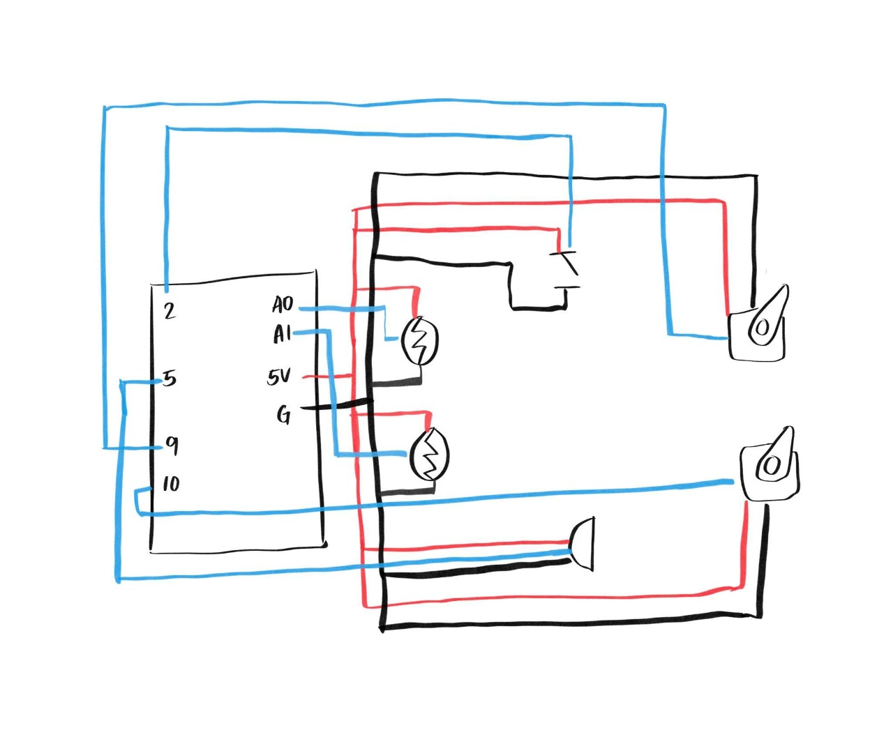
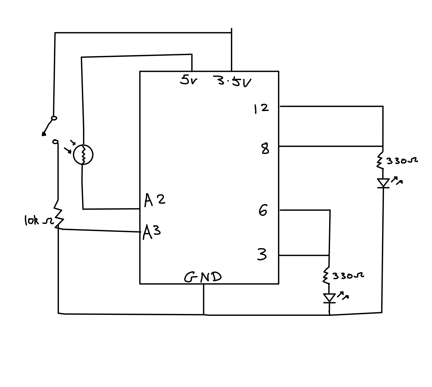
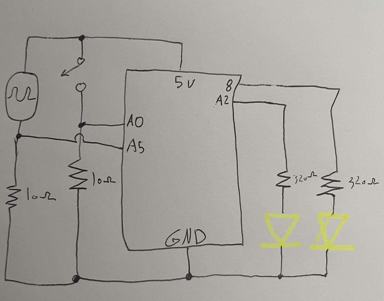
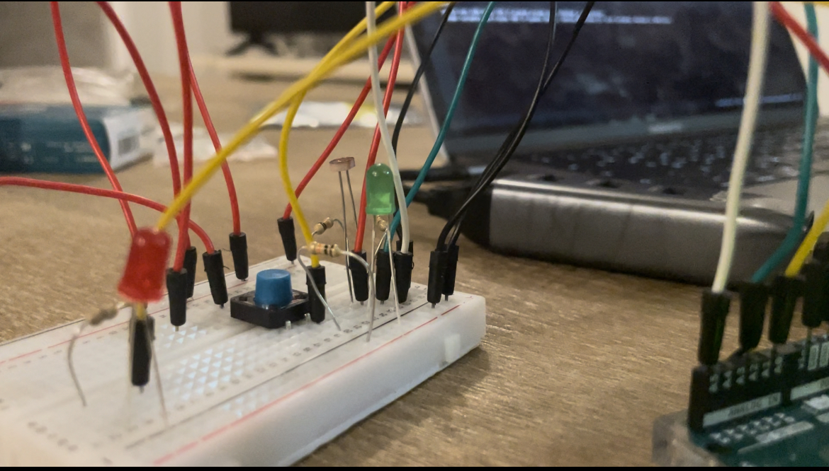
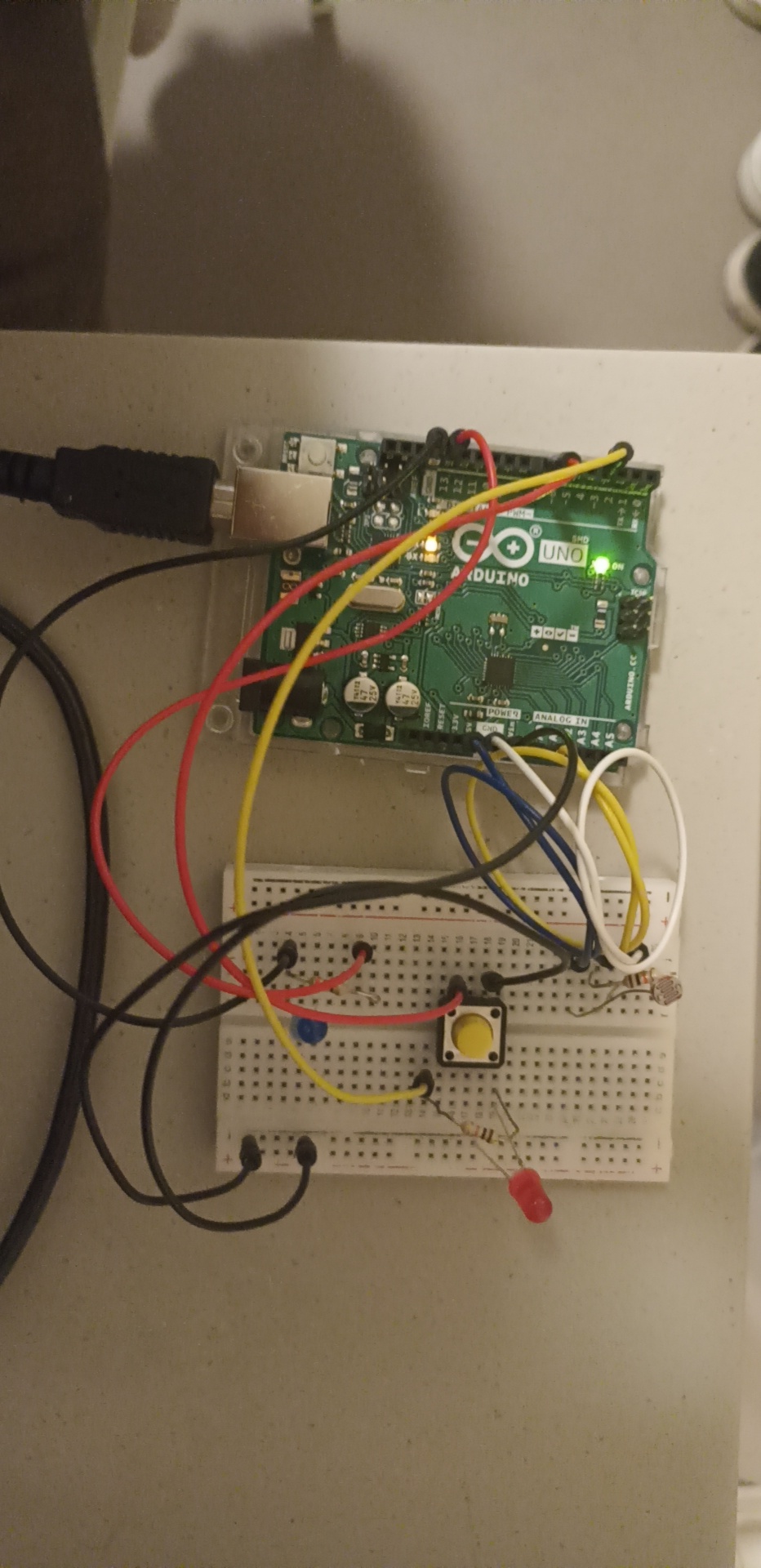
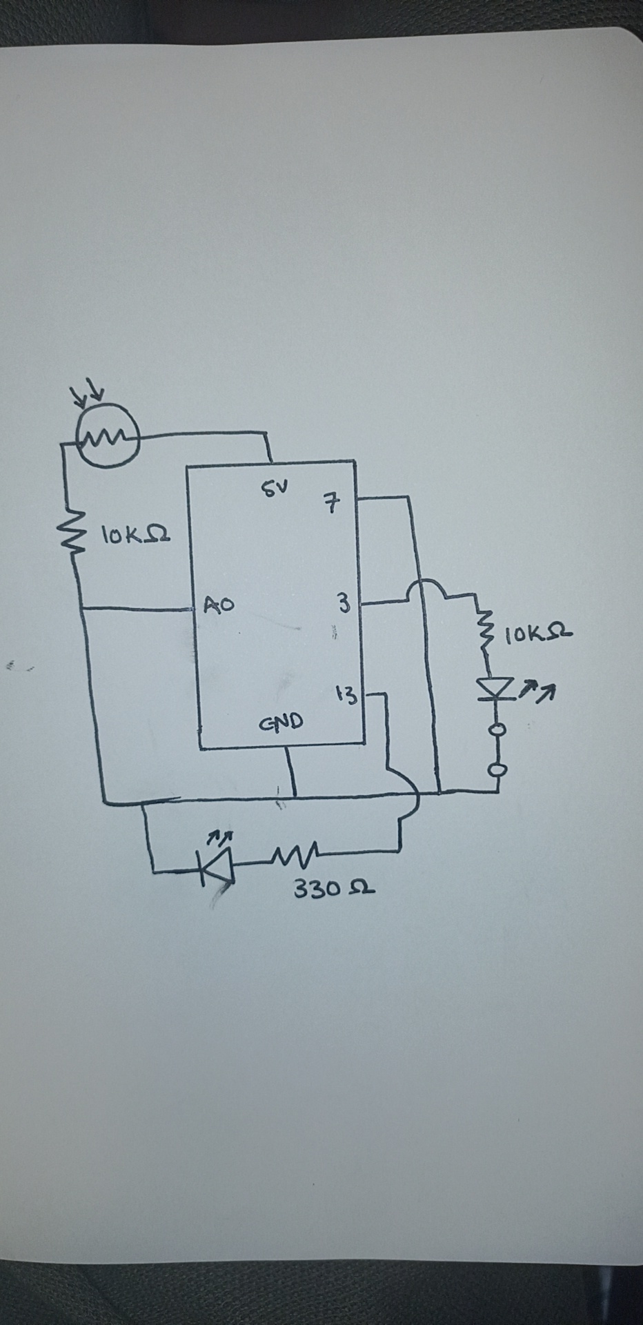
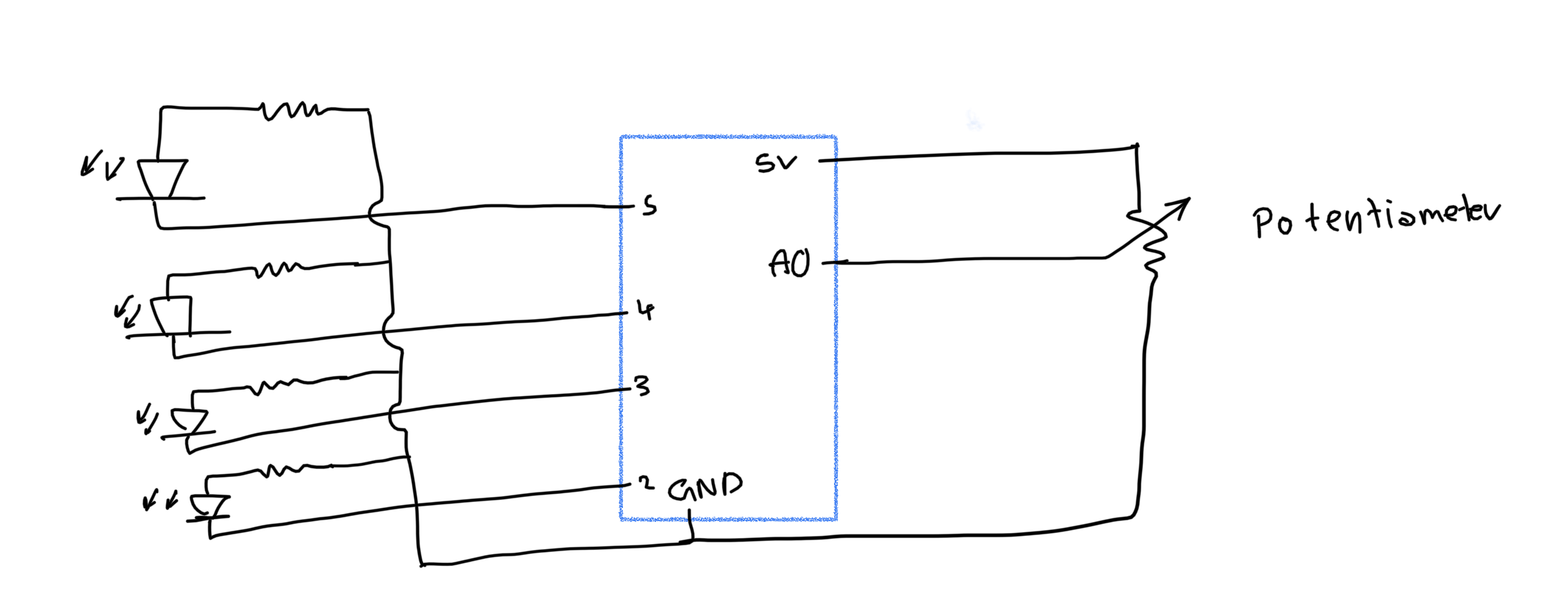
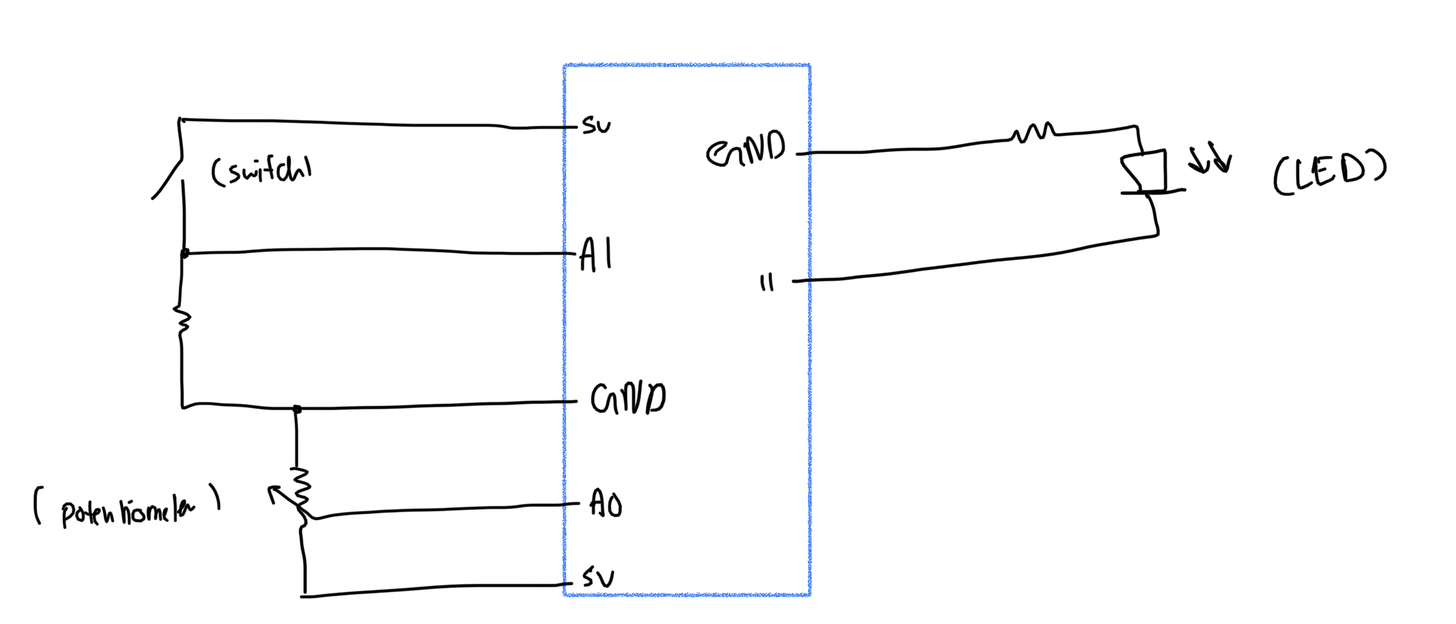
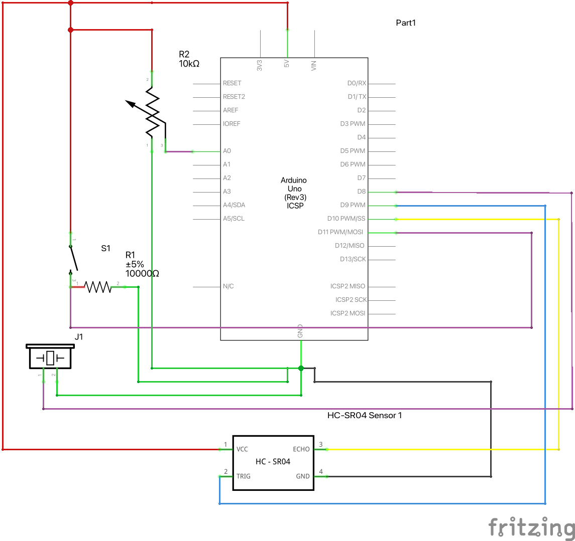
The design of the instrument is based on the schematics as shown below:

Codes

Our code mainly consists of 4 parts: ultrasonic sensor reading, button reading, potentiometer reading, and piezo buzzer output. We first started with ultrasonic sensors, referring to online code for simple distance measurement (Reference). We have slightly modified the original code to our needs.

int findDistance() 
{
  digitalWrite(trigPin, LOW);
  delayMicroseconds(2);

  // Sets the trigPin on HIGH state for 10 micro seconds
  digitalWrite(trigPin, HIGH);
  delayMicroseconds(10);
  digitalWrite(trigPin, LOW);

  // Reads the echoPin, returns the sound wave travel time in microseconds
  long duration = pulseIn(echoPin, HIGH);
  return (duration * 0.034 / 2);
}

This code above is a function that we used to measure distance using the ultrasonic sensor for each loop. Depending on the position of the object, the buzzer will produce different pitches of sound.

Then, the button comes in. Button is used to offset the starting position of the instrument. By placing an object in front of the sensor and pushing the button, the object’s position will automatically be set as a C4 note. Using this button, a player can adjust the instrument in a way that he or she is most comfortable with.

  if (millis() - currentTime > 200 || currentTime == 0) 
  {
    // If the switch is pressed, reset the offset
    if (digitalRead(11) == 1) 
    {
      distanceOffset = findDistance();
      Serial.print("new offset: ");
      Serial.println(distanceOffset);
      currentTime = millis();
    }
  }

  int distance = findDistance() - distanceOffset;

As shown above, when the button is pressed, the program will subtract the offset from the sensor reading.

int pitch_ = intoNotes(map(distance, 0, 20, 1, 7)); 

int pitch = pitch_ * myList[0];
int toneDuration = myList[1];

if(distance <= 20)
  {
    tone(pPin, pitch,toneDuration);                              // Controls 1. PinNumber, 2. Frequency, 3. Time Duration
  }
else
  {
    noTone(pPin);
  }

float intoNotes(int x)
{
  switch(x)
  {
    case 1:
      return 261.63;
    case 2:
      return 293.66;
    case 3:
      return 329.63;
    case 4:
      return 349.23;
    case 5:
      return 392.00;
    case 6:
      return 440.00;
    case 7:
      return 493.88;
    default:
      return 0;
  }
}

The code above is how a program produces different pitches depending on the distance. The program maps 20 cm into 7 different integers; depending on the value of the mapped value, intoNotes() will return a specific pitch value accordingly. If the distance is above 20cm, the instrument will simply not produce a sound.

The code consists of two more functionalities which is facilitated by the function titled “noteModifier()”. It is a void function that takes the data read from the potentiometer as an argument.

void noteModifier(int volt)
{
  float val1 = 0;

  if (volt > 4 && volt <= 4.6)
    val1 = 5;
  else if (volt > 3 && volt <= 4)
    val1 = 4;
  else if (volt > 2 && volt <= 3)
    val1 = 3;
  else if (volt > 1 && volt <= 2)
    val1 = 2;
  else
    val1 = 1;

  myList[0] = val1;
  myList[1] = val1 * 1000;
  
}


As a potentiometer is an analog sensor, it is connected to the A0 pin for a contiguous set of data that ranges from 0 to 1023. Before using this data as input, the values are mapped to a new scale of (1.0 to 5.0) V as the maximum emf in the circuit is 5V. The conversion is done by these lines of code at the beginning of the loop() function.

pVoltRead = analogRead(potentioPin);
trueVolt = (pVoltRead * 5.0/1023);
Serial.println(trueVolt);

Once the true volt in the potentiometer is calculated, the function noteModifier() uses a set of if-conditions to determine the value of a variable named ‘val1’. As seen in the code, the value of ‘val1’ varies based on the range of the true volt argument. The true purpose of using val1 is to alter the content of a global list “myList[]” declared at the beginning of the project. The list consists of two elements: (1) the first element is a coefficient that scales the frequency of the sound produced by the buzzer and (2) the second element is the duration of a single tone produced by the buzzer.

This way, the function determines two primary arguments — frequency and time duration — of the Arduino’s inbuilt function tone().

The idea here is to replicate the real-life application of the project. A user can rotate the knob in the potentiometer; consequently, different tones are produced for varying lengths of time. In short, including a potentiometer provides one additional layer of user interaction to the system. The second demo clip shows the functionality of the potentiometer and how it can be used to produce different tunes.

Reflection / Future Improvements

Working on this assignment was very entertaining and exciting. We were able to use different sensors in the kit and use them to create an object that we can physically interact with, unlike p5js. We believe the instrument came out as we initially expected, but there are a few points that we can improve upon:

      • Ultrasonic Sensor
        • Ultrasonic sensor uses sound waves to measure the distance. This means the measurement can be inaccurate and unreliable depending on the surface of the object the wave is hitting. Due to this, we found out our instrument malfunctions when trying to play it with our own hands. To improve this, we would like to use a laser distance sensor that is less affected by the object’s surface.
      • Piezo Buzzer
        • Piezo Buzzer is very simple to use, but its sound quality is great. If we use a better speaker, we may be able to add more interesting functionalities, such as producing different sounds of instruments when a button is pressed.

Watch demos of the instrument here:

Without potentiometer:

With potentiometer:

GitHub Link

analog input & output

For this assignment I had to get info from at least one analog and one digital sensor using two LEDs. There were different attempts to do this, as well as various outcomes. I experimented with using some methods to connect the LEDs to the sensor as well as the LEDs to the switch button.

A few resources I have found useful:
https://www.youtube.com/watch?v=4fN1aJMH9mM
https://www.youtube.com/watch?v=0p1B74TosTs

The challenge for me was to connect the LEDs to the sensor when I pressed the button and also if I waved over the sensor, it would react on actions. I managed to do it separately for the button and the sensor.

Video:
IMG_5987

Code:


int LDR = 0;
void setup() {
pinMode(12, OUTPUT);
pinMode(13, OUTPUT);
pinMode(A0, INPUT);
Serial.begin(9600);
}
void loop() {
LDR = analogRead(A0);
Serial.println(LDR);
if(LDR < 512) { digitalWrite(12, 1); digitalWrite(13, 1); } else { digitalWrite(12, 0); digitalWrite(13, 0); } }

However, I could not connect the sensor and the button because the light sensor stopped working when I connected the button. I tried redoing my circuit completely, but it was not quite working. It seemed that the button and the light sensor worked together when I could turn the LEDs on with a movement over the sensor and turn them off with the button, but as it turned out later, this was a glitch in the program, not the final result.
In reflection of this, next time I would like to work and understand the code better, so that I could fix the issue I had in this task.

Unusual switch

Concept:

Making a switch with Arduino that lights up a LED when you step on it was an efficient and convenient solution for waking up in the morning. I chose to create this project because I wanted to make something that was easily accessible and user-friendly. The switch was designed to be placed next to the bed, so that when you wake up in the morning, all you have to do is step on it to turn on the LED and start your day.


Reflections and improvements:

Reflecting on the experience of making a switch with Arduino, I found it to be both a difficult and a fun process. Initially, it was challenging for me to come up with an idea for the project. I wanted to create something that was useful and interesting, but I struggled to come up with a specific concept. Eventually, I decided to make a switch that would light up a LED when you step on it, and I found this idea to be both simple and useful. Once I had settled on an idea for the project, the process of creating the switch was enjoyable and rewarding. I enjoyed learning about Arduino and how to use it to create a simple circuit. I also enjoyed writing the program to make the LED light up when the piezo sensor was triggered. This required me to learn some basic programming concepts, such as functions and conditional statements, and I found this to be a challenging but rewarding experience.

Week 10: Musical Instrument

OVERVIEW

for this weeks musical instrument project, we created a DJ setup using servo motors and a piezo buzzer. A digital switch controls the piezo buzzer, which cycles through a series of melodies, while two potentiometers control the servo motors. The potentiometer on the left hand side controls the speed at which the arms rotate, while the potentiometer on the right hand side controls how wide the arm sweeps. A demo of the instrument is shown below. 

DESIGN 

Our original idea was that we wanted to create some type of percussion instrument that would play rhythms rather than notes,  since using the buzzers as the main focus of the instrument felt a bit predictable. Interestingly, the sound and movement of the servo motors reminded us of turn tables, and hence our DJ idea was born. We also really liked using potentiometers to control the rhythm of the servo motors, because the twisting motion of the potentiometers felt very intuitive and similar to the actual motion one would use on a turn table. To add more interest, we decided to add on a buzzer that would play “techno” music to make the entire piece have a clear “club” or “house” atmosphere. 

SCHEMATIC

A schematic of our board is shown below:

CODE 

The instrument gets its input through two analog sensors – the potentiometers, and one digital sensor – the button. As mentioned above, the analog sensors control the servo motors, or the turn tables. Inside our program, the value obtained by the potentiometer is stored in a variables sensorValue1 and sensorValue2. The former is then used to control the delay, or how fast the motor arm is sweeping, while the latter controls the degree to which the arm motor sweeps. This is demonstrated in the code below:

for (pos1 = 0; pos1 <= 60 + sensorValue2/20; pos1 += 1) {
... 
    myservo1.write(pos1);              
    myservo2.write(pos1);
    delay(sensorValue1/50);    
}

On the other hand, the digital sensor controls which melody the piezo will play. Our program has an array of 3 different techno melodies (called melodies[], each 16 notes each. We cycle through each melody by defining a variable called melodyState, which ranges from 0-2, corresponding to the length of the melodies[] array, and increments each time the button is clicked. This is demonstrated in the following code:

In the beginning of loop() calculating the melodyState:

int buttonState1 = digitalRead(pushButton1);

 if (buttonState1==HIGH) {
   add = true; 
 }

if (add) {
   melodyState++;
   add=false;
 }
if (melodyState>=3) melodyState=0;

Using melodyState to index into the melodies[] array:

if (pos1%frequency==0) {
  tone(5, melody[melodyState][melodyCount], length);
  delay(50);
  noTone(5);

  melodyCount++;
  if (melodyCount >=16) { 
    melodyCount = 0; 
  }

CHALLENGES  & IMPROVEMENTS

One of the challenges of this project was the wiring. Because we had so many elements we wanted to incorporate, we did struggle with the circuit getting cut off in certain places where we added new elements. Also, because we used two potentiometers, and one of them was directly connected to 5V, and all other elements were connected to this potentiometer, this meant that when it was turned all the way down, all the power was shut off and the circuit broke. In terms of what we would like to improve, we thought it would be cool to add lights that would flash in correspondence with the melody that was playing, though because our board was already very cluttered, we opted against it. (As shown in the demo, it is a little difficult to maneuver given the tight space). We do, however, think it is worth experimenting with spreading our circuit across multiple breadboards. For example, it would be nice to have the servo motors and potentiometers on one board, and the buzzer and lights on another.  

Musical Instrument

OVERVIEW

for this weeks musical instrument project, we created a DJ setup using servo motors and a piezo buzzer. A digital switch controls the piezo buzzer, which cycles through a series of melodies, while two potentiometers control the servo motors. The potentiometer on the left hand side controls the speed at which the arms rotate, while the potentiometer on the right hand side controls how wide the arm sweeps. A demo of the instrument is shown below. 

DESIGN 

Our original idea was that we wanted to create some type of percussion instrument that would play rhythms rather than notes,  since using the buzzers as the main focus of the instrument felt a bit predictable. Interestingly, the sound and movement of the servo motors reminded us of turn tables, and hence our DJ idea was born. We also really liked using potentiometers to control the rhythm of the servo motors, because the twisting motion of the potentiometers felt very intuitive and similar to the actual motion one would use on a turn table. To add more interest, we decided to add on a buzzer that would play “techno” music to make the entire piece have a clear “club” or “house” atmosphere. 

SCHEMATIC

A schematic of our board is shown below:

CODE 

The instrument gets its input through two analog sensors – the potentiometers, and one digital sensor – the button. As mentioned above, the analog sensors control the servo motors, or the turn tables. Inside our program, the value obtained by the potentiometer is stored in a variables sensorValue1 and sensorValue2. The former is then used to control the delay, or how fast the motor arm is sweeping, while the latter controls the degree to which the arm motor sweeps. This is demonstrated in the code below:

for (pos1 = 0; pos1 <= 60 + sensorValue2/20; pos1 += 1) {
... 
    myservo1.write(pos1);              
    myservo2.write(pos1);
    delay(sensorValue1/50);    
}

On the other hand, the digital sensor controls which melody the piezo will play. Our program has an array of 3 different techno melodies (called melodies[], each 16 notes each. We cycle through each melody by defining a variable called melodyState, which ranges from 0-2, corresponding to the length of the melodies[] array, and increments each time the button is clicked. This is demonstrated in the following code:

In the beginning of loop() calculating the melodyState:

int buttonState1 = digitalRead(pushButton1);

 if (buttonState1==HIGH) {
   add = true; 
 }

 if (add) {
   melodyState++;
   add=false;
 }
if (melodyState>=3) melodyState=0;

Using melodyState to index into the melodies[] array:

if (pos1%frequency==0) {
  tone(5, melody[melodyState][melodyCount], length);
  delay(50);
  noTone(5);

  melodyCount++;
  if (melodyCount >=16) { 
    melodyCount = 0; 
  }

CHALLENGES  & IMPROVEMENTS

One of the challenges of this project was the wiring. Because we had so many elements we wanted to incorporate, we did struggle with the circuit getting cut off in certain places where we added new elements. Also, because we used two potentiometers, and one of them was directly connected to 5V, and all other elements were connected to this potentiometer, this meant that when it was turned all the way down, all the power was shut off and the circuit broke. In terms of what we would like to improve, we thought it would be cool to add lights that would flash in correspondence with the melody that was playing, though because our board was already very cluttered, we opted against it. (As shown in the demo, it is a little difficult to maneuver given the tight space). We do, however, think it is worth experimenting with spreading our circuit across multiple breadboards. For example, it would be nice to have the servo motors and potentiometers on one board, and the buzzer and lights on another.  

Aisha – Analog & Digital

For my assignment, I initially wanted to have the LED lights off and then turn them on via the switch. Whilst holding the switch, I wanted to use the light sensor to change the brightness by hovering my finger over it. However, I couldn’t figure out how to use the light sensor whilst using a switch. It wasn’t working for me, unfortunately. So instead, I used the switch for blinking lights in sync and the light sensor to decrease the brightness whilst it is covered. For this, I needed: wires, resistors, a pushbutton, a light sensor, and LED lights.

I implemented the code we did in class for blinking and got help from this youtube video https://www.youtube.com/watch?v=d6xLaTxFVM4 to decrease the brightness via the light sensor.

This is the code I used for decreasing the light when the sensor is covered:

void loop() {
  // put your main code here, to run repeatedly:
  int buttonState = digitalRead(pushButton);
  ldr = analogRead(A0);
  brightness = map(ldr,0,1023,0,255);

   analogWrite(6, brightness);
   analogWrite(3, brightness);
}

Schematic Diagram:


Project:


Future Improvements:

  • I’d like to do my original idea
  • I also would like the brightness of the LED light when the sensor isn’t covered to be brighter.
  • I’d also like to get more confident doing the schematic drawing as it did take me a while to figure it out.


Digital & Analog Switch

Concept 

I have inputed both an analog and digital switch to control two LEDs to the same bread board and using the same code. i wanted the digital switch to have a pattern with the red LED and that worked! i also wanted the light detector to turn on when it was dark and I was able to do that! IT was definitely a challenge working with the light detector since i had to rewrite my code a couple of times.

My code  

int buttonState = digitalRead(pushButton);

  if (buttonState == HIGH) {
    digitalWrite(redLEDPin, HIGH);
    delay(20);
    digitalWrite(redLEDPin, LOW);
    delay(300);
    digitalWrite(redLEDPin, HIGH);
    delay(20);
    digitalWrite(redLEDPin, LOW);
    delay(300);
    digitalWrite(redLEDPin, HIGH);
    delay(700);
  }
  allOff();
  delay(1000);

   analogValue = analogRead(LIGHT_SENSOR_PIN); // read the input on analog pin
 
  if(analogValue < ANALOG_THRESHOLD)
    digitalWrite(greenLEDPin, HIGH); // turn on LED
  else
    digitalWrite(greenLEDPin, LOW);
}

This is the main part of my code that controls both LEDs functions.

I tried to draw a circuit, Its not perfect but i enjoyed it

Arduino 

Improvement 

I would like to be able to use the analog switch better since I believe that I am not that a-custom to it yet. I also really want to tidy my breadboard for it to be more organized since I got lost with the wires sometimes


stop… go!


concept:

During this week’s exercise assignment, we were encouraged to explore Arduino and digital outputs such as the LED. As a result, I decided to delve into the delay function to make a traffic light system that accurately mimics the ones we see outside campus.


process:

An essential element I intended to present was the creative aspect of the project. As a result, I ended up making a traffic light-like cut out in addition to previewing an image of a  street behind the Arduino to make it more realistic.


sketch: (click, wait till red lights blink to end)


future improvements:

Presenting an analog aspect would have been the next step, in the sense of adding a button that possibly controls two different traffic lights.

Assignment 6: Digital & Analog Sensors – The Street Lamp

Concept: 

For this assignment, I carried forward my concept from the last project. I wanted to make a circuit that included the use of a photoresistor, primarily because it could help me imitate a street lamp. As a child, I was always fascinated by street lamps and their magical tendency to somehow detect when it was dark and turn on.

The photoresistor could pick up environmental light levels and control one of the LEDs. However, I also wanted to enact the mental image of someone using a physical switch to control the lamps so that was also a conceptual integration

Implementation:

For the circuit for the light-dependant LED, I started put by connecting the LED in a pattern where the LDR would control the amount of voltage provided. My line of thinking was that I could in turn create a code that would give me light-level readings from the LDR and allow me to control the LED in real-time. However, I could not  figure out how to make it work so I decided to take inspiration from some sources;

LED Control with LDR (Photoresistor) and Arduino

Turn On & Off of LED with Photoresistor

After implementing the circuit, I was able to calibrate the code and modify it to fit the ambient light levels of my room. It allowed me to create a loop that runs constantly to detect the light and as soon as it drops below a certain level, it allows the LED to receive a charge and emit light.

The following code checks for the light levels and loops constantly and detect any changes in the light levels:

int ResistorStatus = analogRead(LDRPinNum);   //read the status of the LDR value

//check if the LDR status is more than/ equal to 500
//if it is, the LED is HIGH

 if (ResistorStatus <=500) {

  digitalWrite(LEDPinNum, HIGH);               //turns LED on
  Serial.println("It is  dark now, time for light");
  
 }
else {

  digitalWrite(LEDPinNum, LOW);          //turn LED off
  Serial.println(".............");
}

After this, I wanted to create a circuit and code that would control the button and the attached LED when the LDR circuit wasn’t working appropriately. For that, I used a code that would basically detect the state of the button and control the LED depending on that. if the button was pressed it would turn on and then a reversal statement would reverse the state of the button on the next press and turn the LED off.

The Diagram for the Circuit:

Video of the Project running:

Light-Sensitive Street Lamp Project Video Link

Reflection:

For this project, the main challenge was learning a seamless way to create unique code in C+. So far I have only dabbled in JS so this is a new experience for me but thankfully there are seemingly infinite resources online available for free for this. Additionally, I was also challenged by the hand-drawn diagram for my circuit. I think it took me way longer than it should have because I was scared of making mistakes but it seemed easier once I actually started making it. also, I’m glad I learned to draw circuits this way because it’s much more intuitive and takes less time than rendering it out on an editor.

also, one of the best things I learned during this exercise was that you can actually do cable management on Arduino! All you have to do is twist them into small loops. et voila! but i still have a ways to go lol

Analog and Digital sensors

for this project I used the potentiometer to control which LED is turned on. I used mapping to map the sensor’s values to values between 2-5 (the LED pin numbers)

I used this snippet to turn the current LED on and turn the surrounding LEDs off.

digitalWrite((aSensor-1)%6, LOW);
digitalWrite(aSensor, HIGH);
digitalWrite((aSensor+1)%6, LOW);


here is how the circuit looked like (I accidentally drew this with the output to the left and input to the right unlike the convention)

here is a video of the LEDs

This video shows the LEDs without turning off the previous LEDs ((aSensor-1)%6)

I also wanted to use a pushbutton and a potentiometer to control an LED. I used the potentiometer to control how often the LED flickers (I used an array of values to control the brightness of the LED to make it look like it’s flickering) and I used the pushbutton to control if the LED turns on or off.

analogWrite(LED, flicker[current_ficker_value]*LED_on);
delay(aSensor);

The previous code takes a value from the array called flicker and multiplies that by LED_on. LED_on is a viable that equals 1 after the button is clicked and is set to 0. the potentiometer then sets the delay value (which is mapped between 30-100).
here is a picture of the circuit

here is a video of it running:

some things I tried but didn’t work:
    • tried to change the brightness of the LED by multipling the brightness Array by a certain franction but the numbers did not vary enough to show (becuase the fraction I multiplied with was too small(1.5 which is number that when multiplied by the largest number in the array returns 255))
    • I also tried to use a fucntion that takes a variable; whether the LED is on or off, and runs through the flicker array but I realized that becuase the I used a for loop to go through the flicker “stages” the response to the push button wasn’t being processed until the end of that for loop. this made it look like it wasn’t responsive
    • I finally decided to use a variable I increment in the loop function using (current_ficker_value = (current_ficker_value+1)%7;)