
OVERVIEW
for this weeks musical instrument project, we created a DJ setup using servo motors and a piezo buzzer. A digital switch controls the piezo buzzer, which cycles through a series of melodies, while two potentiometers control the servo motors. The potentiometer on the left hand side controls the speed at which the arms rotate, while the potentiometer on the right hand side controls how wide the arm sweeps. A demo of the instrument is shown below.
DESIGN
Our original idea was that we wanted to create some type of percussion instrument that would play rhythms rather than notes, since using the buzzers as the main focus of the instrument felt a bit predictable. Interestingly, the sound and movement of the servo motors reminded us of turn tables, and hence our DJ idea was born. We also really liked using potentiometers to control the rhythm of the servo motors, because the twisting motion of the potentiometers felt very intuitive and similar to the actual motion one would use on a turn table. To add more interest, we decided to add on a buzzer that would play “techno” music to make the entire piece have a clear “club” or “house” atmosphere.
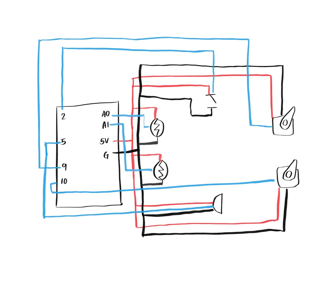
SCHEMATIC
A schematic of our board is shown below:
CODE
The instrument gets its input through two analog sensors – the potentiometers, and one digital sensor – the button. As mentioned above, the analog sensors control the servo motors, or the turn tables. Inside our program, the value obtained by the potentiometer is stored in a variables sensorValue1 and sensorValue2. The former is then used to control the delay, or how fast the motor arm is sweeping, while the latter controls the degree to which the arm motor sweeps. This is demonstrated in the code below:
for (pos1 = 0; pos1 <= 60 + sensorValue2/20; pos1 += 1) {
...
    myservo1.write(pos1);
    myservo2.write(pos1);
    delay(sensorValue1/50);
}
On the other hand, the digital sensor controls which melody the piezo will play. Our program has an array of 3 different techno melodies (called melodies[], each 16 notes each. We cycle through each melody by defining a variable called melodyState, which ranges from 0-2, corresponding to the length of the melodies[] array, and increments each time the button is clicked. This is demonstrated in the following code:
In the beginning of loop() calculating the melodyState:
int buttonState1 = digitalRead(pushButton1);

 if (buttonState1==HIGH) {
   add = true;
 }

if (add) {
   melodyState++;
   add=false;
 }
if (melodyState>=3) melodyState=0;
Using melodyState to index into the melodies[] array:
if (pos1%frequency==0) {
  tone(5, melody[melodyState][melodyCount], length);
  delay(50);
  noTone(5);

  melodyCount++;
  if (melodyCount >=16) {
    melodyCount = 0;
  }
CHALLENGES & IMPROVEMENTS
One of the challenges of this project was the wiring. Because we had so many elements we wanted to incorporate, we did struggle with the circuit getting cut off in certain places where we added new elements. Also, because we used two potentiometers, and one of them was directly connected to 5V, and all other elements were connected to this potentiometer, this meant that when it was turned all the way down, all the power was shut off and the circuit broke. In terms of what we would like to improve, we thought it would be cool to add lights that would flash in correspondence with the melody that was playing, though because our board was already very cluttered, we opted against it. (As shown in the demo, it is a little difficult to maneuver given the tight space). We do, however, think it is worth experimenting with spreading our circuit across multiple breadboards. For example, it would be nice to have the servo motors and potentiometers on one board, and the buzzer and lights on another.