Week 10: A Drum with electronic sounds 🤖 [Aliya & Gautham]

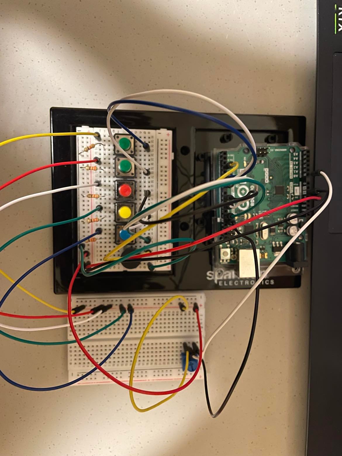
For this week’s assignment, we have created a drum with an electronic sound. The idea is that you can control drum sticks (pencils) by tapping the press sensors. To move the drum sticks, we attached them to servo controllers and taped them to the box.

We also have added the button as a digital read, so that a user can change the producing sound. There are four modes of playing the instrument. You can play it by producing sound yourself or by adding extra notes to your play. 

To provide a louder sound, we used a speaker instead of a buzzer. After finishing with the functioning part of the work, we decided to add led lights, which would light up whenever the drum sticks touch the box.

#include <Servo.h>
#include "pitches.h"

Servo drum1;
Servo drum2;

int drum1Pin = 5;
int drum2Pin = 3;
int ledPin1 = 8;
int ledPin2 = 2;
int switchPin = 7;
int speaker = 6;

int prevButton;

// play sound or not
bool buzzer = false;


int interval = 250;
unsigned long timer1 = 0;
unsigned long timer2 = 0;

// play different notes with drum beat
int index = -1;
int notes[] = {NOTE_D5, NOTE_F4, NOTE_C4};

void setup() {
  drum1.attach(drum1Pin);
  drum2.attach(drum2Pin);
  pinMode(ledPin1, OUTPUT);
  pinMode(ledPin2, OUTPUT);
  pinMode(switchPin, INPUT);
  pinMode(speaker, OUTPUT);
  pinMode(speaker2, OUTPUT);
}

void loop() {
  int force1 = analogRead(A0);
  int force2 = analogRead(A1);

  int button = digitalRead(switchPin);

  if(button == 1 && prevButton == 0){
    if (index == -1){
      buzzer = true;
      index++;
    }
    else if (index == 2){
      buzzer = false;
      index = -1;
    }
    else{
      index++;
    }
  }

  prevButton = button;

  if(force1 > 800){
    // move the servo
    drum1.write(0);
    digitalWrite(ledPin1, HIGH);
    if(buzzer){
      if (index >= 0){
        // play sound as well
        tone(speaker, notes[index], interval*0.25);
      }
    }
  }
  else{
    // timer to allow the servo to return 
    if(millis() > timer1){
        drum1.write(40);
        digitalWrite(ledPin1, LOW);
        timer1 = millis() + interval;
    }
  }

  // for the second servo
  if(force2 > 800){
    drum2.write(0);
      digitalWrite(ledPin2, HIGH);
      if(buzzer){
      tone(speaker, notes[index], interval*0.25);
    }
  }
  else{
    if(millis() > timer2){
        drum2.write(50);
          digitalWrite(ledPin2, LOW);
        timer2 = millis() + interval;
    }
  }
}


Nicholas and Shama – Flute Box

For this assignment we decided to use pressure sensors to create a synth sound when pressed. We placed our sensors on a box and programmed everything on P5js and connected it with Arduino using serial control.

After getting our sound to work, we quickly realized that our chosen notes (c4,E4,G4,C5) more closely resemble a digital flute. We then aligned our sensors to the side of the box to mimic the setup of a flute, but in the medium of a box. Of course, our flute box has no air involved but the pressure added to the sensor does change the intensity of the sound produced which is pretty similar to how a flute intrinsically works.

We controlled the flow of data with a variable controlled with a switch, and only sent data to p5js if the switch was toggled using the sample code from class.

 while (Serial.available() > 0 && toggled) {

      // read the incoming byte:

    int analogReading = analogRead(FORCE_SENSOR_PIN);

    int analogReading1 = analogRead(FORCE_SENSOR_PIN1);

    int analogReading2 = analogRead(FORCE_SENSOR_PIN2);

    int analogReading3 = analogRead(FORCE_SENSOR_PIN3);

    Serial.print(analogReading);

    Serial.print(",");

    Serial.print(analogReading1);

    Serial.print(",");

    Serial.print(analogReading2);

    Serial.print(",");

    Serial.print(analogReading3);

    Serial.print("\n");

    Serial.println();

  }


To output the sound input by the sensors, we created an array of MonoSynth instances, in which each instance controlled the note being played and the volume.

monoSynth = [

      new p5.MonoSynth(),

      new p5.MonoSynth(),

      new p5.MonoSynth(),

      new p5.MonoSynth(),

  ];

  notes = [‘C4', 'E4', 'G4', 'C5']

function playSynth(i, val) {

  userStartAudio();

  let intval = int(val)

  let note = notes[i];

  // note velocity (volume, from 0 to 1)

  let velocity = intval<100?0:map(intval, 0, 1023, 0, 1);

  // time from now (in seconds)

  let time = 0;


  // note duration (in seconds)

  let dur = 1/6;

  if(intval > 100)

    monoSynth[i].play(note, velocity, time, dur);

}

if (inString.length > 0) {

    let sensors = split(inString, ","); // split the string on the commas

    if (sensors.length == 4) {

      // if there are three elements

      for(let i=0; i < sensors.length; i++){

        playSynth(i, sensors[i]);

      }

    }

  }


Since the velocity parameter in monoSynth.play() is continuous, we were able to map the input value to a value between 0 and 1, so when the user presses a key heavier, the sound plays louder.

Musical Instrument (Ahsen and Mariam)

Goal and Implementation

We aimed to build a  pianoesque instrument, comprising of multiple push switches (as the digital inputs) to play different musical notes (C4, D4, E4, F4, G4). But given our breadboard’s size, we couldn’t attach too many switches for the wide array of notes, so we used a potentiometer (as the analog input) to further expand our range of pitches to play.

#include "pitches.h"

const int buzzerPin = 3;
const int button_C4 = 5;
const int button_D4 = 7;
const int button_E4 = 9;
const int button_F4 = 11;
const int button_G4 = 13;


void setup() {
  // put your setup code here, to run once:

  pinMode(buzzerPin, OUTPUT);
  pinMode(button_C4, INPUT);
  pinMode(button_D4, INPUT);
  pinMode(button_E4, INPUT);
  pinMode(button_F4, INPUT);
  pinMode(button_G4, INPUT);

}

void loop() {
  // put your main code here, to run repeatedly:

  int potValue = analogRead(A0);
  int mappedPotValue = map(potValue, 0, 1023, -200, 200);

  int buttonstate_C4 = digitalRead(button_C4);
  int buttonstate_D4 = digitalRead(button_D4);
  int buttonstate_E4 = digitalRead(button_E4);
  int buttonstate_F4 = digitalRead(button_F4);
  int buttonstate_G4 = digitalRead(button_G4);
  
  if(buttonstate_C4 == 1)
    {
      tone(buzzerPin, NOTE_C4+mappedPotValue, 50);
    }
    if(buttonstate_D4 == 1)
    {
      tone(buzzerPin, NOTE_D4+mappedPotValue, 50);
    }
    if(buttonstate_E4 == 1)
    {
      tone(buzzerPin, NOTE_E4+mappedPotValue, 50);
    }
    if(buttonstate_F4 == 1)
    {
      tone(buzzerPin, NOTE_F4+mappedPotValue, 50);
    }
    if(buttonstate_G4 == 1)
    {
      tone(buzzerPin, NOTE_G4+mappedPotValue, 50);
    }

}
/*************************************************
 * Public Constants
 *************************************************/
#define NOTE_B0  31
#define NOTE_C1  33
#define NOTE_CS1 35
#define NOTE_D1  37
#define NOTE_DS1 39
#define NOTE_E1  41
#define NOTE_F1  44
#define NOTE_FS1 46
#define NOTE_G1  49
#define NOTE_GS1 52
#define NOTE_A1  55
#define NOTE_AS1 58
#define NOTE_B1  62
#define NOTE_C2  65
#define NOTE_CS2 69
#define NOTE_D2  73
#define NOTE_DS2 78
#define NOTE_E2  82
#define NOTE_F2  87
#define NOTE_FS2 93
#define NOTE_G2  98
#define NOTE_GS2 104
#define NOTE_A2  110
#define NOTE_AS2 117
#define NOTE_B2  123
#define NOTE_C3  131
#define NOTE_CS3 139
#define NOTE_D3  147
#define NOTE_DS3 156
#define NOTE_E3  165
#define NOTE_F3  175
#define NOTE_FS3 185
#define NOTE_G3  196
#define NOTE_GS3 208
#define NOTE_A3  220
#define NOTE_AS3 233
#define NOTE_B3  247
#define NOTE_C4  262
#define NOTE_CS4 277
#define NOTE_D4  294
#define NOTE_DS4 311
#define NOTE_E4  330
#define NOTE_F4  349
#define NOTE_FS4 370
#define NOTE_G4  392
#define NOTE_GS4 415
#define NOTE_A4  440
#define NOTE_AS4 466
#define NOTE_B4  494
#define NOTE_C5  523
#define NOTE_CS5 554
#define NOTE_D5  587
#define NOTE_DS5 622
#define NOTE_E5  659
#define NOTE_F5  698
#define NOTE_FS5 740
#define NOTE_G5  784
#define NOTE_GS5 831
#define NOTE_A5  880
#define NOTE_AS5 932
#define NOTE_B5  988
#define NOTE_C6  1047
#define NOTE_CS6 1109
#define NOTE_D6  1175
#define NOTE_DS6 1245
#define NOTE_E6  1319
#define NOTE_F6  1397
#define NOTE_FS6 1480
#define NOTE_G6  1568
#define NOTE_GS6 1661
#define NOTE_A6  1760
#define NOTE_AS6 1865
#define NOTE_B6  1976
#define NOTE_C7  2093
#define NOTE_CS7 2217
#define NOTE_D7  2349
#define NOTE_DS7 2489
#define NOTE_E7  2637
#define NOTE_F7  2794
#define NOTE_FS7 2960
#define NOTE_G7  3136
#define NOTE_GS7 3322
#define NOTE_A7  3520
#define NOTE_AS7 3729
#define NOTE_B7  3951
#define NOTE_C8  4186
#define NOTE_CS8 4435
#define NOTE_D8  4699
#define NOTE_DS8 4978

https://youtube.com/shorts/3DIUS9Bjmuo

Class Discussion – Aliya and Kashyapa

Hello everyone, here are some questions for tomorrow’s reading discussion:

  1.  Before reading this article what were your thoughts on the future of interaction design? 
  2. Are you satisfied with current technology like iPhones or iPads for example and you don’t think it really needs to improve much?
  3. we were wondering if you had any ideas as to how hands could be integrated into interaction design in a feasible way?
  4. Do you actually use voice interactions like voice assistants on their phones for example? Do you think voice will play a big role in future interaction design?
  5. Would you disagree and think that brain interfaces could be good? What other problems do you think brain interfaces could lead to?
  6. Do you have any ideas as to how something like haptic gloves could be integrated into our daily lives and replace some of our current technology?
  7. As a final thought, do you agree or disagree with the author’s perspective on the future of interaction design?

Analog & Digital – Customer Service

After trying to figure out how to integrate the two switches together, I came up with the idea of using the potentiometer to toggle between three different LEDs – red for a bad face, yellow for a medium face and green for a happy face. This would lead to some sort of customer service device to give feedback on how you feel.

So far I have been understanding the wiring pretty well but to connect the coding with making what I want to physically happen has been slightly difficult. It feels difficult for my brain to wrap around. I was doing okay with the coding part of the first half of the semester, and the wiring physical part we’re learning now – but I’m a little slow to combine them.

In terms of creating this project – It was relatively easy to get the button to work (to turn on the blue LED) and to get the potentiometer connected to the three colored LEDs. With a little help from Juan, I was able to connect the two together and make it such that wen the button is pressed, the blue LED turns on and so does the potentiometer LEDs, and when clicked again, the customer service ‘device’ turns off.

const int redLight = 9;
const int yellowLight = 10;
const int greenLight = 11;
const int blueOnLight = 4;
const int button = 5;

const int LED_number = 3;

int ledState = LOW;     
int lastButtonState;    
int currentButtonState;

void setup()
{
  pinMode(redLight, OUTPUT);
  pinMode(yellowLight, OUTPUT);
  pinMode(greenLight, OUTPUT);
  pinMode(blueOnLight, OUTPUT);
  pinMode(button, INPUT_PULLUP);
  Serial.begin(9600);
  currentButtonState = digitalRead(button);
}

void loop()
{
  int potValue = analogRead(A0);
  int ledChoice = potValue / (1024 / LED_number);

  //for checking if circuit is on or off
  lastButtonState    = currentButtonState;
  currentButtonState = digitalRead(button);

  if(lastButtonState == HIGH && currentButtonState == LOW) {

    // toggle state of LED
    ledState = !ledState;
    
    // control LED arccoding to the toggled state
    digitalWrite(blueOnLight, ledState); 
  }

//for customer service lights
 
  if (ledState == HIGH){
  if (ledChoice > LED_number - 1) {
    ledChoice = LED_number - 1;
  }
  
  else if (ledChoice == 0) {
    digitalWrite(redLight, HIGH);
    digitalWrite(yellowLight, LOW);
    digitalWrite(greenLight, LOW);
  }
  else if (ledChoice == 1) {
    digitalWrite(redLight, LOW);
    digitalWrite(yellowLight, HIGH);
    digitalWrite(greenLight, LOW);
  }
  else {
    digitalWrite(redLight, LOW);
    digitalWrite(yellowLight, LOW);
    digitalWrite(greenLight, HIGH);
  }
  } else {
    digitalWrite(redLight, LOW);
    digitalWrite(yellowLight, LOW);
    digitalWrite(greenLight, LOW);
    }
  Serial.println(potValue);
}

Without further ado, I present you with the customer service device:

Week 11 – Serial Communication – P5js

You will need the P5 Serial App: https://github.com/p5-serial/p5.serialcontrol/releases

Arduino wiring:

Arduino Code:

void setup() {
  Serial.begin(9600);
  pinMode(2, OUTPUT);
  pinMode(5, OUTPUT);
  while (Serial.available() <= 0) {
    Serial.println("0,0"); // send a starting message
    delay(300);              // wait 1/3 second
  }
}

void loop() {
  while (Serial.available() > 0) {
    // read the incoming byte:
   int inByte = Serial.read();
    switch (inByte) {
      case 0:
        digitalWrite(2, LOW);
        digitalWrite(5, LOW);
        break;
      case 1:
        digitalWrite(2, HIGH);
        break;
      case 2:
        digitalWrite(5, HIGH);
        break;
    }

    int sensorValue = analogRead(A0);
    Serial.print(sensorValue);
    Serial.print(",");
    sensorValue = analogRead(A1);
    Serial.print(sensorValue);
    Serial.println();
  }
}

P5js – Editor Code

Exercises:
  1. make something that uses only one sensor  on arduino and makes the ellipse in processing move on the horizontal axis, in the middle of the screen, and nothing on arduino is controlled by processing
  2. make something that controls the LED brightness from processing
  3. take the gravity wind example below and make it so every time the ball bounces one led lights up and then turns off, and you can control the wind from one analog sensor

Gravity Wind (press space bar for new ball drop)

More Resources: https://itp.nyu.edu/physcomp/labs/#Asynchronous_Serial

Week9 assignment – lighthouse

Goal and Implementation

With this assignment I set out to buid a simplified lighthouse using two seperate LEDs.

The yellow LED is controlled by a switch (digital input).  So this LED is either turned on or off, similar to how a lighthouse works at set times during the night.

The red LED is dependant on the intensity of light in the environment. It’s brightness is mapped to the resistance of the LDR that varies with light. Therefore, in absence of light, the LDR’s resistance increases, and the LED glows brighter. In real life, this would mean as the sun sets, the lighthouse would emit more light, hence being more visible to far off ships.

These two LED’s represent two plausable ways lighthouses function. The LDR value is read by the analogue input and the switch value is read by the digital inputs.

const int yLedPin = 2;
const int rLedPin = 7;
const int buttonPin = 3;
bool onOff = LOW;
byte prevButtonState = LOW;

void setup() {
  // put your setup code here, to run once:
  pinMode(yLedPin, OUTPUT);
  pinMode(rLedPin, OUTPUT);
  pinMode(buttonPin, INPUT);
  Serial.begin(9600);

}

void loop() {
  // put your main code here, to run repeatedly:
  byte buttonState  = digitalRead(buttonPin);
  int lightValue = analogRead(A0);
//  Serial.println(lightValue);
  int mappedLightValue = map(lightValue, 500, 900, 255, 0);

  int constrainedLightValue = constrain(mappedLightValue, 0, 255);
  analogWrite(5, constrainedLightValue);

  if (buttonState == HIGH && prevButtonState == LOW) {
    // change blinking to not blinking
    onOff = !onOff;
    digitalWrite(yLedPin, onOff);
  }
  prevButtonState = buttonState;

}


Distance Sensor

For this assignment I had a very similar idea to Maimuna’s post about a car sensor which is usually what comes to mind when thinking of using an ultrasonic sensor. My project is also a car sensor, I just added more LED’s to fit my narrative of a warning meter which should go from “On” to red , to orange, then red proximity (in 2 intervals = 2 LED’s for each color).

I decided to use two LEDs for each level to indicate the different values that represent proximity which go from around 4- 4o, until the range is out of the ultrasonic sensor. Essentially, the last red LED will light up at around an  output of 5, which means the car will hit the wall/object or is dangerously close to it.

I only used 1 white LED because it is only there to indicate that the car is within the range of the sensor to begin determining proximity.

One Issue that I had while working on this would be the LED’s. The first time I hooked everything up the LED’s were noticeably dim, this was not due to the resistors (I used 270 Ohms) but the LED’s themselves. I ended up switching out the LEDs I grabbed from the lab with the ones we had in the box which worked much more brighter as they have a voltage drop of 2.0-2.4v (unlike the ones in the lab, (I still don’t know their voltage drop).

For my demo, I just made a car from a food box and some tires I just taped to the sides.

Week 9 Assignment (Car Sensors)


Inspiration
Car sensors. Whenever an object or car comes very close to our car, it starts beeping and lighting. That was my motivation to create this sensor.

Video/Image

Work

Basically, as an object comes closer to the Ultrasonic sensor, the bulb lights. For the switch, I added a bulb connected switch- simply press the button.

Challenges

I had many issues with this assignment. It was mainly faulty jumper wires and Arduino’s functioning on Mac. At first, Changing jumper wires solved the issue of Ultrasonic sensor’s distance capture. I spent majority time on solving this 'avrdude: stk500_recv():' error. Re-installed the drivers, added new libraries, etc and magically it just started working!

Code

#include <NewPing.h>

const int trig = 12;
const int echo = 13;
const int led = 2;

int duration = 0;
int distance = 0;

void setup() 
{
  pinMode(trig , OUTPUT);
  pinMode(echo , INPUT);
 
  pinMode(led , OUTPUT);
  
  Serial.begin(9600);

}

void loop()
{
  digitalWrite(trig , HIGH);
  delayMicroseconds(200);
  digitalWrite(trig , LOW);

  duration = pulseIn(echo , HIGH);
  distance = (duration/2)  ;
  
  Serial.println(distance);
  
  if ( distance <= 10 )
  {
    digitalWrite(led, HIGH);
  }
  else
  {
    digitalWrite(led, LOW);
  }
}


dora crosswalk!

for this week’s assignment, I struggled to come up with an idea for a few days, until I finally came up with the idea of creating some like this:

the idea was that it was instead a bathroom stall, and using an ultrasonic sensor, the light would either turn on or off, and I would use a side switch as a lock to determine if the light was red or green, occupied or empty. To learn how to use the ultrasonic sensor, I used the Sparkfun Arduino guidebook where they give many different examples and explanations on how to use different items in the kit, as well as a code to use the ultrasonic sensor.  For the coding of the ultrasonic sensor, the most difficult part was getting the sensor to then return the distance it was measuring and use it in the code to determine the color of the light.

In trying to execute the idea, I thought that the switch would either turn on or off, so I couldn’t use it to change color, but instead, I could use the ultrasonic sensor to change the color. I then reconsidered and thought about using the ultrasonic sensor to determine the color of the lights to create a cross-walk where the distance of the pedestrian decided both the color of the light for them to cross and the color of the light for cars to pass by. To incorporate a button I wanted to make it so that if Dora reached the road but didn’t want to cross she could switch the color of the lights, make hers red and the light for the cars green, but I couldn’t get the code to work. I tried using two different if statements which I realized wouldn’t work and instead, I tried using && but what would happen is the lights would be off and turn on with the button, and once on when Dora was close, instead of having a green light and cars a red light they would both quickly flash red and green.

In the end, although it wasn’t what I wanted the button to be used for, I added it as headlights to the car, which wasn’t difficult besides having to be careful with the wires and making sure they were long enough.

In the future I think the more I understand how to code within Arduino, the more I will be able to accomplish.

Here are a few clips of Dora crossing the road!

https://youtube.com/shorts/mXF2TBsvka4