For my final project, I have locked in on the idea of using a gyroscope device to control a ball inside a maze. Since then, I’ve successfully booked the equipment I need from Arts Booking and made considerable progress for my project.
~~The Maze~~
I utilized the p5 play library to help me build the game managers. I loaded two sprites: a cube and a black tile. The cube acts as the player, whereas the tile serves as the wall for the maze. These can be changed at any time.
let map =
    [
    "@@@@@@@@@",
    "@   @   @",
    "@@@ @ @ @",
    "@@@   @ @",
    "@@@@@   @",
    "@@@@@@@@@",
    ];

new Tiles(map, 0.5, 0.5, 1, 1); //Those are the coordinates so that they start a bit right and not super too the edge of the windowWidth & windowHeight
Within the short period between the previous class, I was able to fully build the maze system complete with a character controller. The Tiles() function can read any list consisting of strings. Those strings are made out of @ and ‘SPACES’ to mark walls and empty space. Next, I made a separate list called map that has the layout of the whole maze. Hence, with this system, I can create as many mazes as I need to and easily implement a map randomizer for the final product.
if (kb.pressed('up') && isOpen(avatar.x, avatar.y-1)) {
    //SMOOTH MOVEMENT USING VECTOR
    avatar.moveTo(createVector(avatar.x, avatar.y-1), .1)

    //avatar.y--;
The character moves by a simple UP, DOWN, LEFT, RIGHT checking alongside isOpen() function. The function checks whether there is a ‘SPACE’ within the map. If there is, it returns true, which means the player can walk through it. If not, then there is a wall and the player cannot move through it.
~~The Physical Controller~~
The module that I booked from Equipments Center is a generic GY-85 sensor that comes with three features: an accelerometer, gyroscope, and magnetometer.
The author, Graham Pullin, makes an interesting case that the design of assistive technologies and products for people with disabilities has often been overly utilitarian and has neglected aesthetics, identity, and broader quality of life considerations. He argues that assistive devices should be designed not just for narrow functionality but as fashionable, desirable consumer products that can enhance the user’s self-image and social interactions.
Pullin’s perspective aligns with the modern social model of disability, which holds that people are often more disabled by environmental and socio barriers rather than by their physical or mental impairments. Well-designed assistive products can help break down those barriers. And by making such products stylish and attractive to use, they may also help combat the stigma frequently associated with disability and assistive tech.
I agree with Pullin’s core ideas. Too often, assistive devices have looked medical, institutional, and perhaps alienating marking the user as different in a negative way. But that’s not always true. For example, Eyeglasses have evolved from purely functional visual aids to fashion accessories worn even by those who don’t medically require them. One could make an argument that other kinds of aids could potentially become part of someone’s fashion.
The author argues for diversity and choices in design but this is not always desirable. Sometimeshaving too many choicesjust makes the user more confused as we discussed in earlier articles, and a more simplistic approach is the best.
Redesigning already established tools won’t necessarily solve all the issues associated with the negative stigma surrounding disability. For example, you might improve wheelchair design, andmake it more techy and futuristic, but again one will always see it as a wheelchair and I doubt it will become a fashion theme in the general public. Additionally, even if you improve wheelchair design, it’s all about the surrounding environment that makes it accessible, which should often be a key focus. With more complex design choices affordability becomes a problem. More elaborate choices in eyewear have made them pretty expensive where people chase brand values and collaborations rather than their actual utility.
Despite, all these I firmly believe that creativity always emerges on top and people will find ways to make all “disability” associated designs more mainstream. Nevertheless, we should not forget that first of all, it’s about core utility and accessibility and less about mainstream fashion trends. If costs become marginal, then perhaps one could view them in the same terms. We are far from that future but not as far as one might have imagined when the article was originally published.
During class, we were asked to complete, in pairs, three exercises in order to get more familiar with the serial communication between Arduino and p5.js. The exercises asked the following:
EXERCISE 01: ARDUINO TO P5 COMMUNICATION
Make something that uses only one sensor on Arduino and makes the ellipse in p5 move on the horizontal axis, in the middle of the screen, and nothing on Arduino is controlled by p5.
EXERCISE 02: P5 TO ARDUINO COMMUNICATION
Make something that controls the LED brightness from p5.
EXERCISE 03: BI-DIRECTIONAL COMMUNICATION
Take the gravity wind example and make it so:
Every time the ball bounces, one LED lights up and then turns off
And you can control the wind from one analog sensor
Therefore, in order to complete the assignment effectively, we split it respectively, and we communicated along the execution, since we needed to make sure we were not only following instructions adequately, but that we could finish on time.
Exercise #1 and #2 – Marcos Hernández
For this assignment, there was not any tweaking of the code done in the file provided (W11_01_Bidirectional_Com.ino) alongside the class presentation in Week 12.
So, for the set-up, I just prepared the Arduino in a way that it functions with the code without being modified, since it already did everything needed for these two exercises. Although, in p5.js, I duplicated the example that we were provided on class to work with. Likewise, I did make changes since it would not replicate what was needed for exercise #1 and #2.
After setting up the Arduino, we have the following:
And with this code in p5.js that is modified so as every time the circle is clicked, the red LED gets turn on as well as having the possibility of moving it horizontally with a potentiometer via analog values:
let rVal = 0;
let alpha = 255;
let left = 0; // True (1) if mouse is being clicked on left side of screen
let right = 0; // True (1) if mouse is being clicked on right side of screen

function setup() {
  createCanvas(640, 480);
  textSize(18);
}

function draw() {
  // one value from Arduino controls the background's red color
  background(255)

  // the other value controls the text's transparency value
  fill(255, 0,0)

  if (!serialActive) {
    text("Press Space Bar to select Serial Port", 20, 30);
  } else {
    text("Connected", 20, 30);
    // Print the current values
    text('rVal = ' + str(rVal), 20, 50);
    text('alpha = ' + str(alpha), 20, 70);
  }

  // click on one side of the screen, one LED will light up
  // click on the other side, the other LED will light up
  if (mouseIsPressed) {
    if (mouseX > rVal-50 && mouseX < rVal+50 && mouseY > height/2-50 && mouseY < height/2+50) {
      right = 1;
    }
  } else {
    right = 0;
  }
  ellipse(rVal, height/2, 50,50)
}

function keyPressed() {
  if (key == " ") {
    // important to have in order to start the serial connection!!
    setUpSerial();
  }
}

// This function will be called by the web-serial library
// with each new *line* of data. The serial library reads
// the data until the newline and then gives it to us through
// this callback function
function readSerial(data) {
  ////////////////////////////////////
  //READ FROM ARDUINO HERE
  ////////////////////////////////////

  if (data != null) {
    // make sure there is actually a message
    // split the message
    let fromArduino = split(trim(data), ",");
    // if the right length, then proceed
    if (fromArduino.length == 2) {
      // only store values here
      // do everything with those values in the main draw loop

      // We take the string we get from Arduino and explicitly
      // convert it to a number by using int()
      // e.g. "103" becomes 103
      rVal = int(fromArduino[0]);
      alpha = int(fromArduino[1]);
    }

    //////////////////////////////////
    //SEND TO ARDUINO HERE (handshake)
    //////////////////////////////////
    let sendToArduino = left + "," + right + "\n";
    writeSerial(sendToArduino);
  }
}
We have the following result observed in the video:
After completing these exercises, I started to feel more confident as to how I will work on my final project.
Exercise #3 – Marwan AbdElhameed
This one is particular was challenging. Basically, the sensor data is sent to Arduino after mapping it to -1,1, then the Y position of the ball is sent to the Arduino and checked if it was >330. If it is, the LED at is switched to HIGH.
The code found in p5.js:
let velocity;
let gravity;
let position;
let acceleration;
let wind;
let drag = 0.99;
let mass = 50;

function setup() {
  createCanvas(640, 360);
  noFill();
  position = createVector(width/2, 0);
  velocity = createVector(0,0);
  acceleration = createVector(0,0);
  gravity = createVector(0, 0.5*mass);
  wind = createVector(0,0);
}

function draw() {
    if (!serialActive) {
    text("Press s to select Serial Port", 20, 30);
  } else {
    text("Connected", 20, 30);
    // Print the current values
    text('rVal = ' + str(rVal), 20, 50);
    text('alpha = ' + str(alpha), 20, 70);
  }

  background(255);
  applyForce(wind);
  applyForce(gravity);
  velocity.add(acceleration);
  velocity.mult(drag);
  position.add(velocity);
  acceleration.mult(0);
  ellipse(position.x,position.y,mass,mass);
  if (position.y > height-mass/2) {
      velocity.y *= -0.9;  // A little dampening when hitting the bottom
      position.y = height-mass/2;
    }
}

function applyForce(force){
  // Newton's 2nd law: F = M * A
  // or A = F / M
  let f = p5.Vector.div(force, mass);
  acceleration.add(f);
}

function keyPressed(){
  if (keyCode==LEFT_ARROW){
    wind.x=-1;
  }
  if (keyCode==RIGHT_ARROW){
    wind.x=1;
  }
  if (key==' '){
    mass=random(15,80);
    position.y=-mass;
    velocity.mult(0);
  }
   if (key == 's') {
    // important to have in order to start the serial connection!!
    setUpSerial();
  }
}

function readSerial(data) {
  ////////////////////////////////////
  //READ FROM ARDUINO HERE
  ////////////////////////////////////

  if (data != null) {
    // make sure there is actually a message
    // split the message
    let fromArduino = split(trim(data), ",");
    // if the right length, then proceed
    if (fromArduino.length == 1) {

      wind = int(fromArduino[0]);
    }

    //////////////////////////////////
    //SEND TO ARDUINO HERE (handshake)
    //////////////////////////////////
    let sendToArduino = position.y + "\n";
    writeSerial(sendToArduino);
  }
}
The code sent to the Arduino:
int leftLedPin = 2;

void setup() {
  // Start serial communication so we can send data
  // over the USB connection to our p5js sketch
  Serial.begin(9600);

  // We'll use the builtin LED as a status output.
  // We can't use the serial monitor since the serial connection is
  // used to communicate to p5js and only one application on the computer
  // can use a serial port at once.
  pinMode(LED_BUILTIN, OUTPUT);

  // Outputs on these pins
  pinMode(leftLedPin, OUTPUT);

  // Blink them so we can check the wiring
  digitalWrite(leftLedPin, HIGH);
  delay(200);
  digitalWrite(leftLedPin, LOW);


  // start the handshake
  while (Serial.available() <= 0) {
    digitalWrite(LED_BUILTIN, HIGH); // on/blink while waiting for serial data
    Serial.println("0,0"); // send a starting message
    delay(300);            // wait 1/3 second
    digitalWrite(LED_BUILTIN, LOW);
    delay(50);
  }
}

void loop() {
  // wait for data from p5 before doing something
  while (Serial.available()) {
    digitalWrite(LED_BUILTIN, HIGH); // led on while receiving data

    int left = Serial.parseInt();
    if(left>=330){
       digitalWrite(leftLedPin, HIGH);
}

    if (Serial.read() == '\n') {
      digitalWrite(leftLedPin, left);
      int sensor = analogRead(A0);
      sensor = map(sensor,0,1023,-1,1);
      Serial.println(sensor);

    }
  }
  digitalWrite(leftLedPin, LOW);
}
After sending the setting up the Arduino, sending the code and using the one that was written in p5.js, we have the following result:
Conclusion
Working on Arduino, at first sight, might appear scary and too technical. But with these exercises, both my teammate and I feel more comfortable with the Arduino world. As they say, the hardest step will always be the first, and the rest, should be left to curiousness.
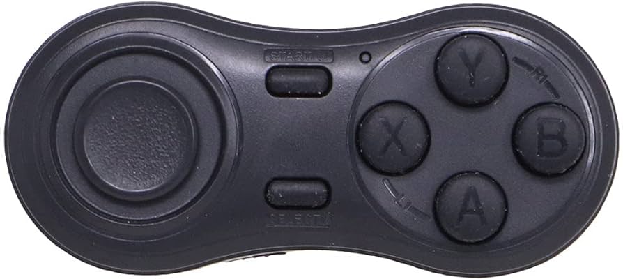
Calling all adventurers! Prepare to embark on a thrilling collaborative treasure hunt with this interactive game. You’ll navigate a top-down world in P5.js using joysticks on custom Arduino controllers.
The Arduino controller is the command center. One joystick translates your movement (up/down/left/right, forward/backward) into smooth exploration in P5.js. Another button activates the metal detector, triggering a response in the game world.
P5.js paints the picture. The user explore a beautifully crafted map, whether it’s a lush forest or a sandy desert. Your character, represented by a sprite or shape, moves based on your joystick actions. Scattered throughout the map are hidden treasures, initially invisible. Keep your eyes and ears peeled!
The metal detector serves as your trusty companion. A visual representation of the detector moves with your character, and it changes color, size, or plays a sound effect when you approach a hidden treasure. This is your hot zone cue! Get closer, and the treasure becomes visible on the map, ready for collection. Your success adds it to your inventory display.
The communication flow is straightforward. Arduino continuously sends joystick movements to P5.js. When you press the metal detector button, Arduino sends a signal indicating activation. The character on P5.js will move according to the received movement data. P5.js sends 2 types of data: The gamestate and signal indicating of the treasure is close. The gamestate will be displayed on the LCD on the controller, while LEDs on the controller will blink if it receives treasure signal.
Furthermore, sound effects will be added for immersive exploration and treasure discoveries. Also, will introduce a timer for a thrilling race against the clock. Consider different treasure types with varying rarities for a more dynamic hunt.
This single-player treasure hunt offers a compelling experience. You can tailor the world, difficulty, and treasure types to your preferences. With the core gameplay established, the possibilities are endless! So grab your controller, unleash your explorer spirit, and embark on a thrilling hunt for hidden treasures!
As I have stated in the previous reading response, one of the main priorities of design should be inclusivity. However, how we approach inclusivity also matters. The way eyeglasses have mutated from medical tool to fashion entity clearly demonstrates the multiple forms it can take in various social models. Ideally speaking, the design of the product should be implemented in a way that it does not imply any negative interpretations in different social models, but this is easier said than done. In any way the design attempts to cover or camouflage the disability would imply the idea that the disability should be something to be ashamed of, but highlighting the disability would also be counterintuitive as it could support segregation.
So how exactly should we approach inclusivity? I believe that the optimal way is to design the object so that it prioritizes functionality but also offers variety. Similar to glasses, regardless of the product in question, there should be different models or designs that could be utilized. This way, the consumer/user would have the opportunity to select according to their liking. This could also be used to counter argue against negative interpretations as it would mainly depend on the user. Design, in this sense, should be flexible, so that it could provide sense of compatibility to the user, which I believe is the ultimate goal of design.
My first idea is to make a physically interactive version of my second assignment. So, the user would move a pen on top of a board. On the pen, there would be a button and a RGB LED mounted on opposite ends. The idea is to make the pen look like a pipette. If possible, I plan to have more than one pipette to represent different strains of bacteria. In that case, there might be one more sensor to identify which “pipette” is being picked up. This would link back to the p5 sketch to control the color of the bacteria.
The board itself would have rows of photoresistors mounted along the length and breadth, meant to detect the light from the LED. The information about the position (obtained from checking which photoresistors get the brightest measurement) will be used to map the bacterial colonies to the p5 sketch, which will then grow on the screen in a way very similar to my assignment.
There are many challenges I foresee. The primary is getting my hands on that many photoresistors. Also, I am not sure if photoresistors have the sensitivity required to differentiate between the light being directly in line vs. off to a small angle. I will also have to eliminate background light, although I have an idea to do so by creating a hood under which the user will have to work. Also, due to the very limited amount of time I have, as well as the amount of other commitments [mainly in the form of Capstone 🙁 ] , it might be hard to implement it.
Idea 2: Braille Translation
My second idea was to kind of make an English-to-Braille translator. On the p5 side, I plan to have the user type out a word. I have two ways of implementing this on the Arduino side:
(a) Using LEDs: In this case, the idea is to serve as a learning aid for Sighted people to learn Braille.
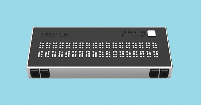
(b) Using Servos to raise pins: This is my preferred means of output, as it would be suitable for both Sighted and Blind people. It would be similar to an already existing device known as a refreshable Braille display.
This project was partially motivated by this project from a couple of years back, which used LEGO Mindstorms to make a Braille printer.
While researching, I also found this handheld refreshable Braille display device made by MIT undergraduates, which serves as a pretty good indication of what the project might look like.
I have three ideas for my final project, each emerging from my interdisciplinary interests.
The first idea I would like to propose is creating a Sign Language Glove, aimed at facilitating communication and improving accessibility for individuals who are deaf or hard of hearing. I shall limit it to fingerspelling using the alphabet for now. The glove will incorporate flex sensors on each finger to detect bending movements. Arduino will process this data and send the finger configurations to a p5.js sketch, which will interpret the gestures and recognize the corresponding letters of the alphabet.
The p5.js screen will display the recognized letters visually and audibly using text-to-speech. Additionally, users will have the option to input letters via a keyboard to display the corresponding Sign for it on the screen. This interactive system enables individuals that use sign language to have two-way communication with non-sign language users effectively.
I initially thought of using American Sign Language (ASL), but the issue is a lot of the signs have the same finger positions, and it will be difficult to differentiate the signs.
An alternative is using Indian Sign Language, which uses two hands, but can overcome the above issue. However, this adds complexity of checking 10 finger configurations.
My second idea is conducting a psychology experiment utilizing p5.js for the visual presentation of stimuli and Arduino for participant response collection. I aim to design either Perception experiments, such as Visual search tasks, which involve participants searching for a target stimulus among distractors, or Cognition experiments, which may involve memory tasks, where participants memorize and recall sequences of stimuli presented, or face recognition tasks, where participants identify familiar faces. In these experiments, the p5.js sketch will display visual stimuli, while Arduino buttons will serve as response inputs.
Eg, in the visual search tasks, the p5.js screen will display each of the trials and participants will use buttons connected to the Arduino board to indicate when they have found the target stimulus. Arduino will record response times and accuracy.
At the end of the experiment session, participants will be able to view their performance metrics and compare them to group averages or previous trials. This setup allows for the seamless integration of psychological experimentation with interactive technology, facilitating data collection and analysis in a user-friendly manner.
For my third project idea, I propose creating an interactive system that generates music from art! The user will be able to draw on the p5.js canvas, creating their unique artwork. The system will then analyze this artwork pixel by pixel, extracting the RGB values of each pixel. These RGB values will be averaged to create a single value for each pixel, which will then be mapped to a musical note. Additionally, the system will detect sharp changes in color intensity between adjacent pixels, indicating transitions in the artwork. These transitions will determine the length of each note, with sharper changes resulting in shorter notes. The coordinates of each drawn point can influence the tempo or volume of the music, to make it sound better. Once the music composition is generated in p5.js, it will be sent to Arduino, where a piezo buzzer will play the music in real-time. This interactive system lets users create their own art and music.
Both readings (basically a two-part reading) were a highly interesting look into future interaction systems, especially using the tactile capabilities of our fingertips to sense and manipulate objects and interaction systems.
Bret Victor’s examples on the range of motion and sensitivity of the human hands and fingers reminded me of a key fact from developmental psychology: the fact that the touch receptors of the fingers, lips, and tongues are the first senses to develop. This is why infants touch everything and put everything into their mouths; it is basically their way of seeing things.
The human fingertip in fact can resolve objects at a resolution of 0.4mm. That means, it can basically distinguish between two objects that are about half of a sharpened pencil tip apart.
Thus, with this level of capability of the human hands, one would be inclined to agree with Victor on the declaration that current systems of interaction are highly limited compared to the possibilities.
Other than that, many touchscreen technologies are unfortunately inacessible for people with disabilities. Blind people, for example, require some kind of haptic or audio feedback from a touchscreen input that is usually never bundled with the hardware. In a lot of cases, there is no sufficient option provided in the default software, and special software needs to be downloaded… by first making one’s way through the device unaided. Old people and people with motor disabilities also often struggle with some of the finer inputs required with touchscreens, again due to the lack of any haptic feedback.
Interaction systems in the future need to be designed for all. But first, we must break away from the status quo and boldy go where no man has gone before.
For this assignment, Amiteash and I wished to create our own recreation of a music box. This was a popular toy/gramophone in the past (depending on how you viewed it) and we even remember having a small old one back at home in India. While they have taken many different forms, we based ours on a simple electronic one that played music when you opened the box.
Components
1 Arduino Uno R3 SMD
1 Photoresistor
1 Slideswitch
1 Arduino Piezo Buzzer
2 10 kΩ Resistor
Jumper Wires
Circuit Schematic and Simulation
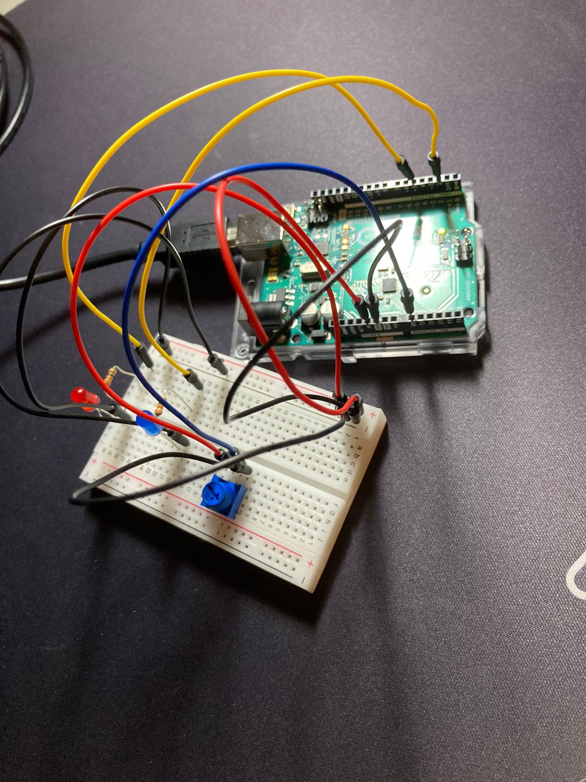
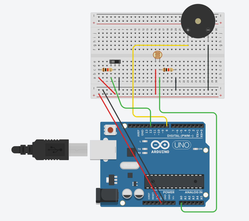
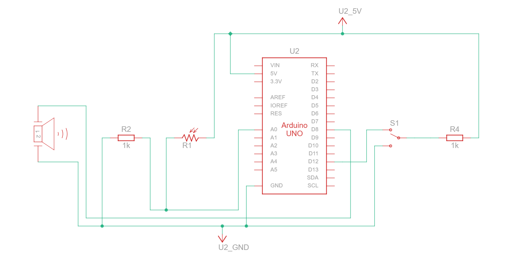
The first step was to prepare a circuit schematic on TinkerCAD. Basically, the digital input took the form of a slideswitch feeding into a digital input pin (pin 4) through a 10 kΩ pull-down resistor. Analog Input came from the photoresistor connected to pin A0. The buzzer output was from pin 8.
Figure 1: Component Simulation View
Figure 2: Schematic View
TinkerCAD also has a handy simulation functionality, that even allows to upload the Arduino code and test how the circuit would work under simulator conditions. This definitely helped in fixing bugs before even testing with the actual circuit, and also helped to individually simulate each component before assembling together.
Usage
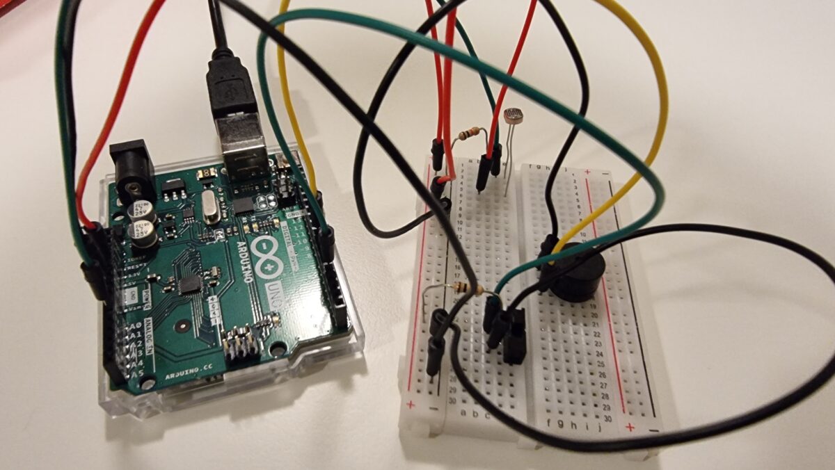
Figure 3: The circuit
Basically, there are two main control points: opening/closing the box, and sliding the switch between ON/OFF.
When the box is opened, light falling on the photoresistor exceeds the threshold and thus triggers the playSong() function, which iterates over the notes in the pre-assigned song and plays it using the buzzer. When the box is closed, the light intensity falls below the threshold and the for loop breaks / is not triggered again, causing the music to stop playing.
When the switch is ‘ON’, pin 4 detects a ‘HIGH’ voltage and thus the Arduino plays song 1, which for this example we chose to be Toby Fox’s Megalovania from the game Undertale.
When the switch is ‘OFF’, pin 4 detects a ‘LOW’ voltage and thus the Arduino plays song 2, which for this example we chose to be Mikkel Fabricus Smitt’s Subway Surfers Main Theme from the game Subway Surfers.
#define LDR_PIN A0
#define SWITCH_PIN 4
#define BUZZER_PIN 8

#include "pitches.h"

int ldrThreshold = 500;

void setup() {
  pinMode(LDR_PIN, INPUT);
  pinMode(SWITCH_PIN, INPUT);
  pinMode(BUZZER_PIN, OUTPUT);
}

void loop() {
  // Read the light level from the LDR
    int lightLevel = analogRead(LDR_PIN);
    Serial.println(lightLevel);
  // If the light level exceeds the threshold, play the first song
  if (lightLevel > ldrThreshold) {
      // Check if the switch is pressed to change to the second song
    if (digitalRead(SWITCH_PIN) == LOW) {
      playSong(2);
      // Add some delay to prevent rapid switching
      delay(10); }
    else {
      playSong(1);
      delay(10);    }
  }
  else {
    noTone(BUZZER_PIN);
  }
}

void playSong(int songNumber) {
  // Define the melody and duration for each song
  int melody1[] = { NOTE_D4, NOTE_D4, NOTE_D5, NOTE_A4, 0, NOTE_GS4, NOTE_G4, NOTE_F4, NOTE_D4, NOTE_F4, NOTE_G4,
  NOTE_C4, NOTE_C4, NOTE_D5, NOTE_A4, 0, NOTE_GS4, NOTE_G4, NOTE_F4, NOTE_D4, NOTE_F4, NOTE_G4,
  NOTE_B3, NOTE_B3, NOTE_D5, NOTE_A4, 0, NOTE_GS4, NOTE_G4, NOTE_F4, NOTE_D4, NOTE_F4, NOTE_G4,
  NOTE_AS3, NOTE_AS3, NOTE_D5, NOTE_A4, 0, NOTE_GS4, NOTE_G4, NOTE_F4, NOTE_D4, NOTE_F4, NOTE_G4
   };
  int noteDurations1[] = { 8, 8, 4, 4, 8, 4, 4, 4, 8, 8, 8,
   8, 8, 4, 4, 8, 4, 4, 4, 8, 8, 8,
   8, 8, 4, 4, 8, 4, 4, 4, 8, 8, 8,
    8, 8, 4, 4, 8, 4, 4, 4, 8, 8, 8
  };

  int melody2[] = {
  NOTE_C5, 0, NOTE_C5, 0, NOTE_AS4, 0, NOTE_A4, 0,
  NOTE_AS4, 0, NOTE_AS4, NOTE_C5, 0, NOTE_AS4, NOTE_A4, 0,
  0,
  NOTE_C5, 0, NOTE_AS4, 0, NOTE_A4, 0, NOTE_AS4, 0, NOTE_E5,
  0,

  NOTE_C5, 0, NOTE_C5, 0, NOTE_AS4, 0, NOTE_A4, 0,
  NOTE_AS4, 0, NOTE_AS4, NOTE_C5, 0, NOTE_AS4, NOTE_A4, 0,
  0,
  NOTE_C5, 0, NOTE_AS4, 0, NOTE_A4, 0, NOTE_AS4, 0, NOTE_E4,0
};

int noteDurations2[] = {
  8, 16, 8, 16, 8, 16, 8, 16,
  8, 16, 8, 8, 16, 8, 8, 16,
  4,
  8, 16, 8, 16, 8, 16, 8, 4, 8,
  4,

  8, 16, 8, 16, 8, 16, 8, 16,
  8, 16, 8, 8, 16, 8, 8, 16,
  4,
  8, 16, 8, 16, 8, 16,8,4,8,4
};

  // Select the melody and note durations based on the song number
  int *melody;
  int *noteDurations;
  int notes;

  if (songNumber == 1) {
    melody = melody1;
    noteDurations = noteDurations1;
    notes = sizeof(melody1) / sizeof(melody1[0]);
  } else {
    melody = melody2;
    noteDurations = noteDurations2;
    notes = sizeof(melody2) / sizeof(melody2[0]);
  }

  // Play the selected melody
  for (int i = 0; i < notes; i++) {
    //Read light level from LDR
    int lightLevel = analogRead(LDR_PIN);
    if(lightLevel > ldrThreshold){
      int duration = 1000 / noteDurations[i]; //duration in ms for each note
      tone(BUZZER_PIN, melody[i], duration);
      delay(duration * 1.3); // Add a slight delay between notes for better sound quality
      noTone(BUZZER_PIN);
    } else{
      break; //to stop playing song immediately if box is closed
    }
  }
}
The notes refer to the pitches.h header file from the toneMelody example on Arduino IDE.
To switch between two different songs, we assigned the information about the songs to pointers. Also, to ensure that the song switched off as soon as possible when the switch or photoresistor were toggled, we used an if statement that led to a statement to break the loop, which immediately stops playing.
The notes and durations were obtained from this Github repository: https://github.com/hibit-dev/buzzer/tree/master. Since the repository did not have the notes for Megalovania, that was manually transformed from its sheet music online.
Showcase
Reflections
We both really enjoyed working on this project. For something that was relatively simple, it was still quite impressive. We were especially happy with the solution we found in using the break statement. Because earlier, the photoresistor was only taking an input after the ‘for’ loop was completed, and thus the song kept playing even when the box was closed, contrary to our expectations. Breaking the loop avoids that issue. Overall, it was fun listening to our favorite game theme tunes on loop!
For this project, Aneeka and I wished to create our own recreation of a music box (or musical box, for those from the Commonwealth). This was a popular toy/gramophone in the past (depending on how you viewed it) and we even remember having a small old one back at home in India. While they have taken many different forms, we based ours on a simple electronic one that played music when you opened the box.
Figure 1: A music box
Components
1 Arduino Uno R3 SMD
1 Photoresistor
1 Slideswitch
1 Arduino Piezo Buzzer
2 10 kΩ Resistor
Jumper Wires
Circuit Schematic and Simulation
The first step was to prepare a circuit schematic on TinkerCAD. Basically, the digital input took the form of a slideswitch feeding into a digital input pin (pin 4) through a 10 kΩ pull-down resistor. Analog Input came from the photoresistor connected to pin A0. The buzzer output was from pin 8.
Figure 1: Component Simulation View
Figure 2: Schematic View
TinkerCAD also has a handy simulation functionality, that even allows to upload the Arduino code and test how the circuit would work under simulator conditions. This definitely helped in fixing bugs before even testing with the actual circuit, and also helped to individually simulate each component before assembling together.
Basically, there are two main control points: opening/closing the box, and sliding the switch between ON/OFF.
When the box is opened, light falling on the photoresistor exceeds the threshold and thus triggers the playSong() function, which iterates over the notes in the pre-assigned song and plays it using the buzzer. When the box is closed, the light intensity falls below the threshold and the for loop breaks / is not triggered again, causing the music to stop playing.
When the switch is ‘ON’, pin 4 detects a ‘HIGH’ voltage and thus the Arduino plays song 1, which for this example we chose to be Toby Fox’s Megalovania from the game Undertale.
When the switch is ‘OFF’, pin 4 detects a ‘LOW’ voltage and thus the Arduino plays song 2, which for this example we chose to be Mikkel Fabricus Smitt’s Subway Surfers Main Theme from the game Subway Surfers.
Code
#define LDR_PIN A0
#define SWITCH_PIN 4
#define BUZZER_PIN 8

#include "pitches.h"

int ldrThreshold = 500; // Adjust this value according to your LDR sensitivity
int song = 1;

void setup() {
  pinMode(LDR_PIN, INPUT);
  pinMode(SWITCH_PIN, INPUT);
  pinMode(BUZZER_PIN, OUTPUT);
  Serial.begin(9600);
}

void loop() {
  // Read the light level from the LDR
    int lightLevel = analogRead(LDR_PIN);
    Serial.println(lightLevel);
  // If the light level exceeds the threshold, play the first song
  if (lightLevel > ldrThreshold) {
      // Check if the switch is pressed to change to the second song
    if (digitalRead(SWITCH_PIN) == LOW) {
      playSong(2);
      // Add some delay or debounce to prevent rapid switching
      delay(10);
      int song = 1;}
    else {
      playSong(1);
      delay(10);
      int song = 2;    }
  }
  else {
    noTone(BUZZER_PIN);
  }
}

void playSong(int songNumber) {
  // Define the melody and duration for each song
  int melody1[] = { NOTE_D4, NOTE_D4, NOTE_D5, NOTE_A4, 0, NOTE_GS4, NOTE_G4, NOTE_F4, NOTE_D4, NOTE_F4, NOTE_G4,
  NOTE_C4, NOTE_C4, NOTE_D5, NOTE_A4, 0, NOTE_GS4, NOTE_G4, NOTE_F4, NOTE_D4, NOTE_F4, NOTE_G4,
  NOTE_B3, NOTE_B3, NOTE_D5, NOTE_A4, 0, NOTE_GS4, NOTE_G4, NOTE_F4, NOTE_D4, NOTE_F4, NOTE_G4,
  NOTE_AS3, NOTE_AS3, NOTE_D5, NOTE_A4, 0, NOTE_GS4, NOTE_G4, NOTE_F4, NOTE_D4, NOTE_F4, NOTE_G4
   };
  int noteDurations1[] = { 8, 8, 4, 4, 8, 4, 4, 4, 8, 8, 8,
   8, 8, 4, 4, 8, 4, 4, 4, 8, 8, 8,
   8, 8, 4, 4, 8, 4, 4, 4, 8, 8, 8,
    8, 8, 4, 4, 8, 4, 4, 4, 8, 8, 8
  };

  int melody2[] = {
  // NOTE_C4, 0, NOTE_G4, 0, NOTE_AS4, NOTE_C5, NOTE_AS4, 0, NOTE_F4, NOTE_DS4, 0,
  // NOTE_C4, 0, NOTE_G4, 0, NOTE_AS4, NOTE_C5, NOTE_AS4, 0, NOTE_F4, NOTE_DS4, 0,
  // NOTE_C4, 0, NOTE_G4, 0, NOTE_AS4, NOTE_C5, NOTE_AS4, 0, NOTE_F4, NOTE_DS4, 0,

  // NOTE_C4, 0, NOTE_E4, 0, NOTE_G4, NOTE_A4, NOTE_AS4,
  NOTE_C5, 0, NOTE_C5, 0, NOTE_AS4, 0, NOTE_A4, 0,
  NOTE_AS4, 0, NOTE_AS4, NOTE_C5, 0, NOTE_AS4, NOTE_A4, 0,
  0,
  NOTE_C5, 0, NOTE_AS4, 0, NOTE_A4, 0, NOTE_AS4, 0, NOTE_E5,
  0,

  NOTE_C5, 0, NOTE_C5, 0, NOTE_AS4, 0, NOTE_A4, 0,
  NOTE_AS4, 0, NOTE_AS4, NOTE_C5, 0, NOTE_AS4, NOTE_A4, 0,
  0,
  NOTE_C5, 0, NOTE_AS4, 0, NOTE_A4, 0, NOTE_AS4, 0, NOTE_E4,0
};

int noteDurations2[] = {
  // 4, 8, 4, 8, 4, 8, 8, 16, 8, 8, 16,
  // 4, 8, 4, 8, 4, 8, 8, 16, 8, 8, 16,
  // 4, 8, 4, 8, 4, 8, 8, 16, 8, 8, 16,

  // 4, 8, 4, 8, 4, 4, 4,
  8, 16, 8, 16, 8, 16, 8, 16,
  8, 16, 8, 8, 16, 8, 8, 16,
  4,
  8, 16, 8, 16, 8, 16, 8, 4, 8,
  4,

  8, 16, 8, 16, 8, 16, 8, 16,
  8, 16, 8, 8, 16, 8, 8, 16,
  4,
  8, 16, 8, 16, 8, 16,8,4,8,4
};

  // Select the melody and note durations based on the song number
  int *melody;
  int *noteDurations;
  int notes;

  if (songNumber == 1) {
    melody = melody1;
    noteDurations = noteDurations1;
    notes = sizeof(melody1) / sizeof(melody1[0]);
  } else {
    melody = melody2;
    noteDurations = noteDurations2;
    notes = sizeof(melody2) / sizeof(melody2[0]);
  }

  // Play the selected melody
  for (int i = 0; i < notes; i++) {
    //Read light level from LDR
    int lightLevel = analogRead(LDR_PIN);
    Serial.println(lightLevel);
    if((lightLevel > ldrThreshold) || (song == 1 && digitalRead(SWITCH_PIN) == HIGH) || (song == 2 && digitalRead(SWITCH_PIN) == LOW)){
      int duration = 1000 / noteDurations[i];
      tone(BUZZER_PIN, melody[i], duration);
      delay(duration * 1.3); // Add a slight delay between notes for better sound quality
      noTone(BUZZER_PIN);
    } else{
      break;
    }
  }
}
The notes refer to the pitches.h header file from the toneMelody example on Arduino IDE.
The code is not too different from the examples we did in class, which was a major advantage of this project. To switch between two different songs, we assigned the information about the songs to pointers.
Also, to ensure that the song switched off as soon as possible when the switch or photoresistor were toggled, we used an if statement that led to a statement to break the loop, which immediately stops playing.
The notes and durations were obtained from this Github repository: https://github.com/hibit-dev/buzzer/tree/master. Since the repository did not have the notes for Megalovania, that was manually transformed from its sheet music online.
Showcase
Reflections
We both really enjoyed working on this project. For something that was relatively simple, it was still quite impressive.
We were especially happy with the solution we found in using the break statement. Because earlier, the photoresistor was only taking an input after the ‘for’ loop was completed, and thus the song kept playing even when the box was closed, contrary to our expectations. Breaking the loop avoids that issue.

 Help, it’s broken! (nope) Continue reading “Final Project Progress | GyroMaze”