Exercise 1:
Link to the video: https://youtube.com/shorts/4ek33gKQaNY?si=3ArQyArCtsPfHlGx
P5 sketch:
p5.js Code:
let xposition = 100;
function setup() {
  createCanvas(640, 480);
  textSize(18);
}
function draw() {
  background(0, 255, 0);
  fill(0);
  ellipse(xposition, height / 2, 50, 50);
}

function keyPressed() {
  if (key == " ") {
    // Calls a function to set up the serial connection
    setUpSerial();
  }
}

// Function to read data from the serial port
function readSerial(data) {
  // Check if data received is not null
  if (data != null) {
    // Maps the integer value of data from range 0-1023 to 0-640 and updates xposition
    xposition = map(int(data), 0, 1023, 0, 640);
  }
}
Arduino Code:
void setup() {
  // Start serial communication so we can send data
  // over the USB connection to our p5js sketch
  Serial.begin(9600);
}

void loop() {


      int sensor = analogRead(A0);
      delay(5);
      Serial.println(sensor);

}
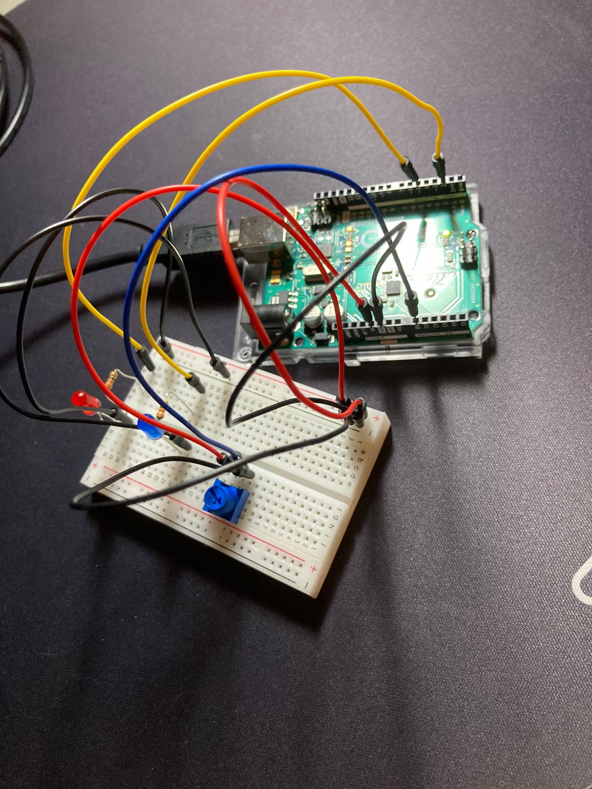
Circuit:

For this exercise, we have utilized the potentiometer to change the position of the ellipse in the p5.js sketch. As shown in the code snippet, the ellipse’s x position is mapped to the value of the potentiometer from the Arduino. First of all, by calling the setUpSerial() function when the space bar is pressed, the p5.js sets up the serial connection with the Arduino. Then, using the readSerial(data) the p5.js reads data regarding the potentiometer value from the Arduino.
For the Arduino, we used Serial. begin(9600) to start the serial communication. Inside the loop function, we have Serial.println(sensor) to send the sensor value to the serial port as a line of text (string), ending in a newline character.
Exercise 2:
Video:
P5 sketch:
P5.js code
In the p5 code, the mouseX is used to control the brightness of the LED light. MouseX is mapped from 0 to width of the canvas to 0 to 255. Utilizing the function readSerial(), we send the value of the mapped mouseX to the Arduino using the below line of codes:
function readSerial(data) {

  if (data != null) {
    //////////////////////////////////
    //SEND TO ARDUINO HERE (handshake)
    //////////////////////////////////
    let sendToArduino = left + "\n";
    writeSerial(sendToArduino);
  }
}
Arduino Code
In the Arduino code, after the initial handshake, the code continuously checks for any data that is sent from the Arduino code. It then parses the sending string and uses that string to control the brightness of the LED using analogWrite. The value has been mapped to the range of 255 so there is no need of mapping again in the Arduino code.
int leftLedPin = 3;


void setup() {
  // Start serial communication so we can send data
  // over the USB connection to our p5js sketch
  Serial.begin(9600);


  // We'll use the builtin LED as a status output.
  // We can't use the serial monitor since the serial connection is
  // used to communicate to p5js and only one application on the computer
  // can use a serial port at once.
  pinMode(LED_BUILTIN, OUTPUT);


  // Outputs on these pins
  pinMode(leftLedPin, OUTPUT);


  // Blink them so we can check the wiring
  digitalWrite(leftLedPin, HIGH);
  delay(200);
  digitalWrite(leftLedPin, LOW);


  // start the handshake
  while (Serial.available() <= 0) {
    digitalWrite(LED_BUILTIN, HIGH); // on/blink while waiting for serial data
    Serial.println("0,0"); // send a starting message
    delay(300);            // wait 1/3 second
    digitalWrite(LED_BUILTIN, LOW);
    delay(50);
  }
}


void loop() {
  // wait for data from p5 before doing something
  while (Serial.available()) {
    digitalWrite(LED_BUILTIN, HIGH); // led on while receiving data


    int left = Serial.parseInt();
    // int right = Serial.parseInt();
    if (Serial.read() == '\n') {
      analogWrite(leftLedPin, left);
      Serial.println();
    }
  }
  digitalWrite(LED_BUILTIN, LOW);
}
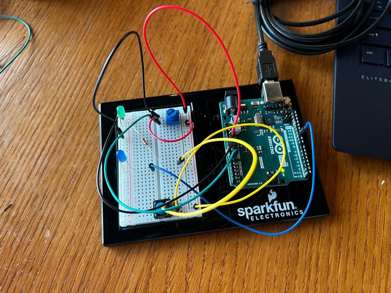
Circuit
Exercise 3
Video:
P5.js Sketch
For the LED to light up every bounce, we assigned a flag “ground”. Every time the ball hits the ground, we set ground = true else it equals to false.
if (position.y > height-mass/2) {
    velocity.y *= -0.9;  // A little dampening when hitting the bottom
    position.y = height-mass/2;
  ground = true;
  }
else{
  ground = false;
}
If ground = true, we will send to Arduino the value of 1, else, we will send 0. We did this because we only use digitalWrite in Arduino which only accepts LOW (0) and HIGH (1) as its value.
if (ground) {
     sendToArduino = "1"+"\n";
    }
    else{
       sendToArduino = "0"+"\n";
    }
For the control of the wind, we used the potentiometer to change the value of the wind. Since there is only one data coming from the Arduino, we didn’t use the trim to parse the function. Instead, we directly map the receiving data to the wind value:
wind.x= map(int(data), 0,1023,-1, 1);
Arduino Code:
int ledPin = 8;


void setup() {
 // Start serial communication so we can send data
 // over the USB connection to our p5js sketch
 Serial.begin(9600);


 // We'll use the builtin LED as a status output.
 // We can't use the serial monitor since the serial connection is
 // used to communicate to p5js and only one application on the computer
 // can use a serial port at once.
 pinMode(LED_BUILTIN, OUTPUT);


 // Outputs on these pins
 pinMode(ledPin, OUTPUT);


 // Blink them so we can check the wiring
 digitalWrite(ledPin, HIGH);
 delay(200);
 digitalWrite(ledPin, LOW);


 // start the handshake
 while (Serial.available() <= 0) {
   digitalWrite(LED_BUILTIN, HIGH); // on/blink while waiting for serial data
   Serial.println("0,0"); // send a starting message
   delay(300);            // wait 1/3 second
   digitalWrite(LED_BUILTIN, LOW);
   delay(50);
 }
}


void loop() {
 // wait for data from p5 before doing something
 while (Serial.available()) {
   digitalWrite(LED_BUILTIN, HIGH); // led on while receiving data


   int led = Serial.parseInt();
   if (Serial.read() == '\n') {
     digitalWrite(ledPin, led);
     int sensor = analogRead(A5);
     Serial.println(sensor);
   }
 }
 digitalWrite(LED_BUILTIN, LOW);
}
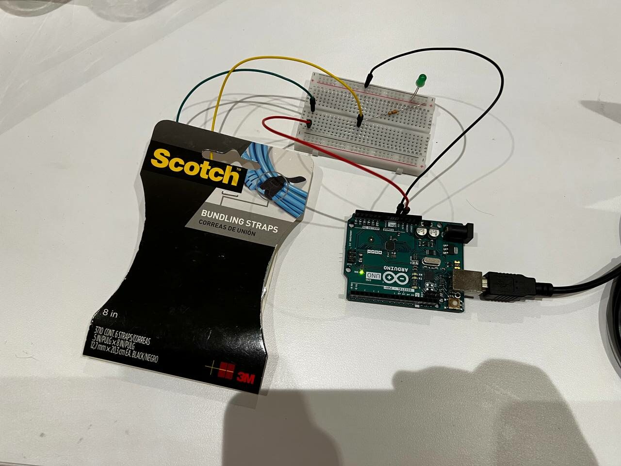
In the Arduino sketch, we initiated serial communication with Serial.begin(9600) within the setup() function to set up data transfer at 9600 bits per second. The ledPin variable is set to 8, corresponding to the pin connected to an LED. We use Serial.available() to check for incoming serial data. Initially, the sketch blinks the LED on pin 8 to verify the correct wiring. When it begins receiving data from the serial port, the built-in LED lights up as a signal of data processing. The received data is then used to control the state or brightness of the LED on pin 8. Additionally, the sketch reads the analog value from pin A5 (connected to a potentiometer) and sends this value back to the p5.js, facilitating a continuous, dynamic interaction between the Arduino hardware and the p5.js.
Circuit:

Reflection:
Initially, we had a bit of a problem understanding how the communication between the p5.js and Arduino works. After spending quite a few investigating the sample code, we identified a few of the differences we had in our code and the sample code that caused our code to not work. We also learnt the mapping of values between the p5.js values and the Arduino values (including both variable resistors and analogWrite ranges).