Exercise 1
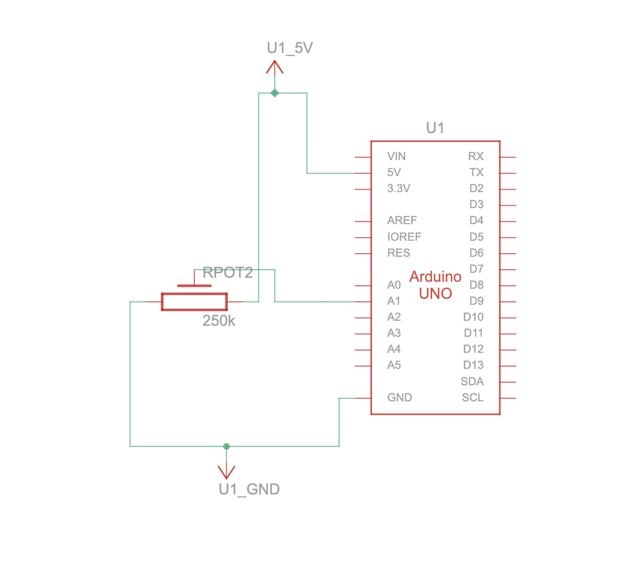
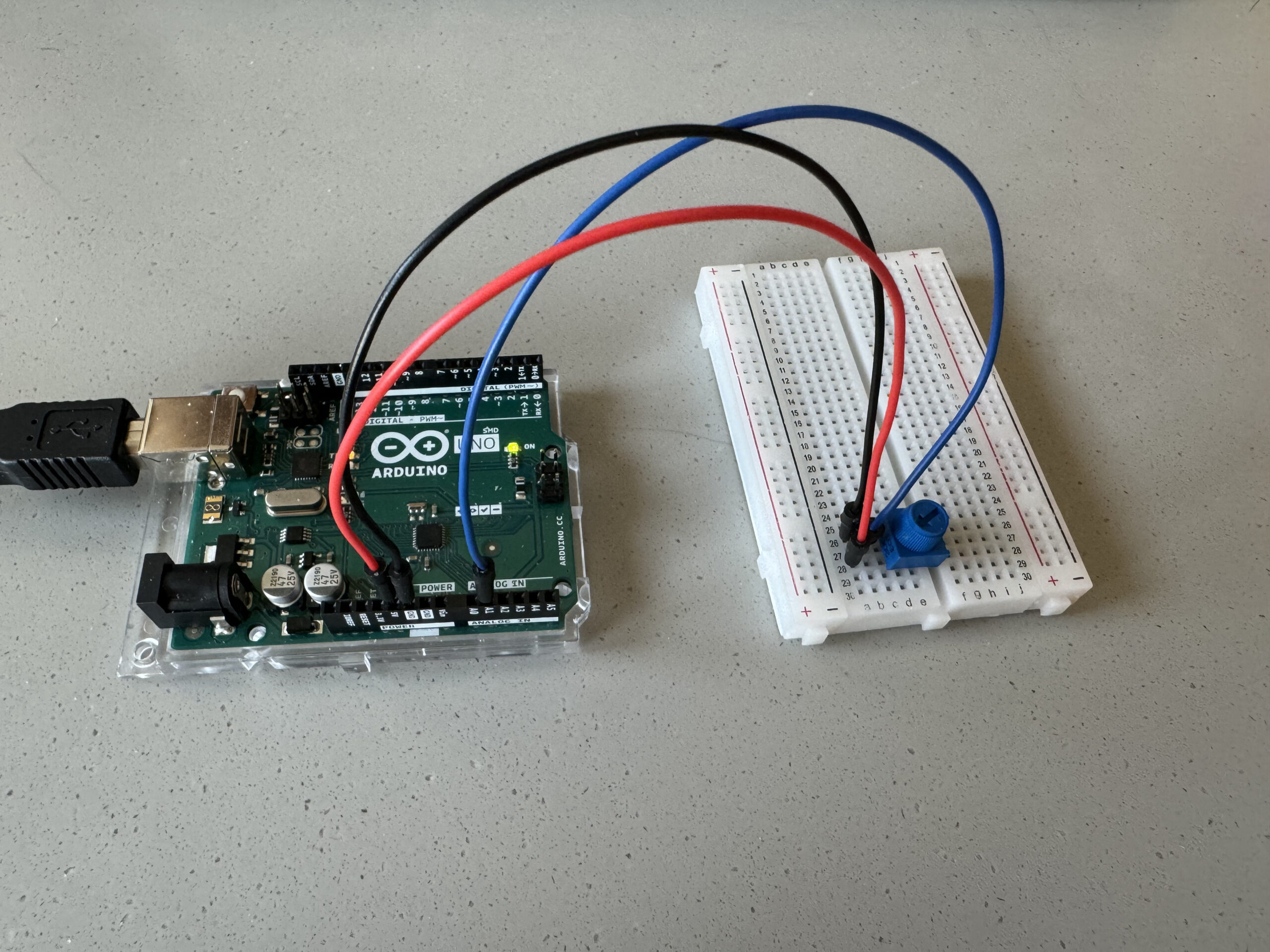
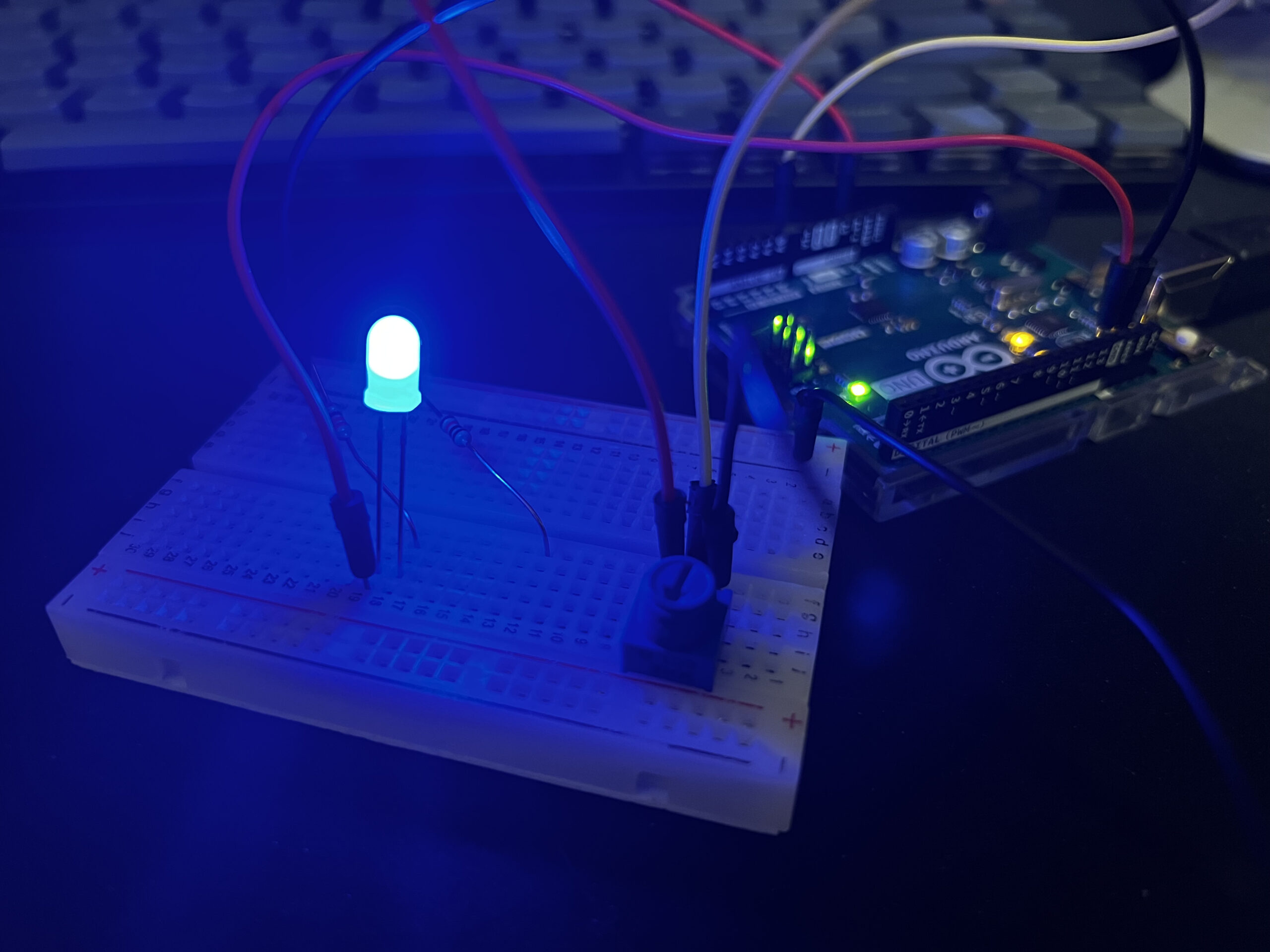
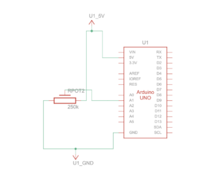
The Arduino continuously reads the electrical signal from a potentiometer. This signal represents the potentiometer’s position based on its rotation. The code then scales this raw sensor reading (ranging from 0 to 1023) to a new range of 0 to 400 using a function called map. This scaled value becomes the control signal for the circle’s movement on the web page.
The scaled sensor value (now within the 0-400 range) is sent from the Arduino to the p5js code running in the web browser. When data arrives to p5js, the code assigns it to a variable named circleX. This variable essentially controls the circle’s position on the screen. Finally, the code uses this value to dynamically adjust the horizontal position (X coordinate) of the circle drawn on the p5js canvas.
Hardware
- Arduino Board
- Potentiometer
- Computer
- Wires
- Breadboard
Picture:

Video:
https://drive.google.com/drive/folders/1hQqnDHH51cl_E2OkjGjJsFP3ax-MFtd5
Schematics:
Exercise 2
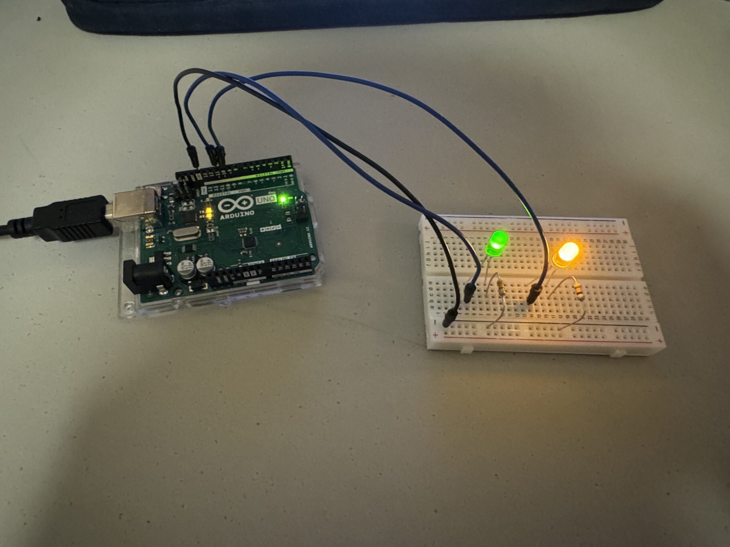
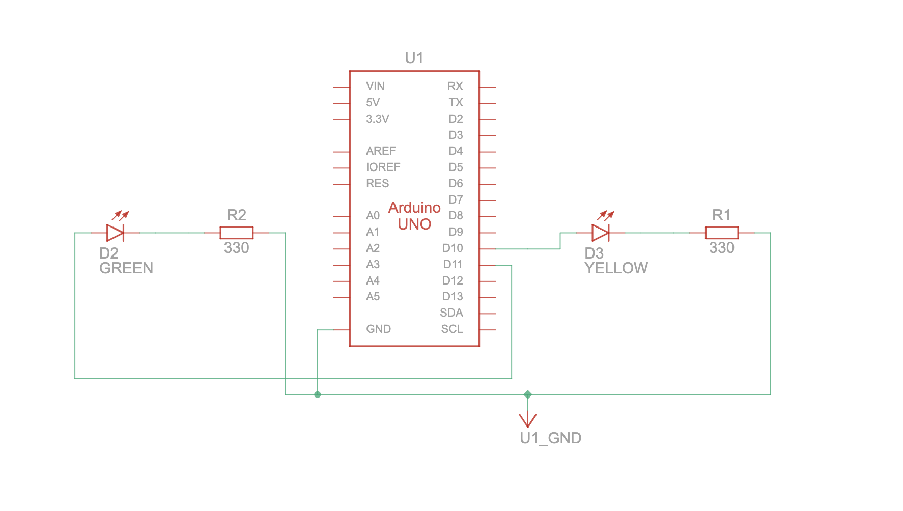
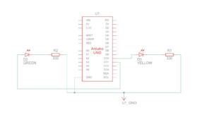
The p5js code continuously tracks the mouse cursor’s position on the canvas (represented by mouseX and mouseY variables). The p5js code directly assigns the mouseX value to the brightness 1 variable and the mouseY value to the brightness2 variable. These variables essentially store the desired brightness levels for the two LEDs. The readSerial function in p5js combines the brightness1 and brightness2 values with a comma (“,”) separator and adds a newline character (“\n”) to create a formatted message. This formatted message is then sent to the Arduino.
Once the data (representing the formatted message) are available, the code reads them using Serial.parseInt. This separates the combined brightness values stored in brightness1 and brightness2. The map function then scales both brightness values from the p5js range (0-400) to the appropriate range (0-255) for controlling the LEDs. The code includes error handling by checking for a newline character (\n) after reading the brightness values. This ensures complete data reception before setting the LED brightness. If no data is received, the Arduino prints an error message “No signal received” to the serial monitor. Finally, the Arduino sets the brightness of each LED (LED 1 on pin 10 and LED 2 on pin 11) based on the corresponding received values (brightness1 and brightness2).
Hardware
Picture:

Video:
https://drive.google.com/drive/folders/1p5D9UuY4ZrFujKK-zVVKQ-zkGdZM75vL
Schematics:
Exercise 3
The p5js code establishes the core mechanics for simulating a bouncing ball on the screen. It defines various physics concepts like: Gravity, Drag, Acceleration and Wind. The code continuously updates the ball’s position and velocity based on the applied forces and drag. When the ball hits the bottom of the canvas, its vertical velocity is reversed, simulating a bounce. At this point, a variable named ledOn is set to 1, indicating the LED should be turned on. If the serial connection is active, the code sends the ledOn value (0 or 1) as a string followed by a newline character (“\n”) to the Arduino using writeSerial.
The readSerial function gets called whenever new data arrives from the Arduino. Here, it parses the received data and assigns it to the windVale variable. This value updates the wind vector, influencing the ball’s horizontal movement in the simulation. The Arduino code continuously reads the analog value from a potentiometer connected to pin A0. It then maps this value (ranging from 0 to 1023) to a new range of -10 to 10 using the map function. This mapped value represents the wind force affecting the ball in the p5js simulation. The Arduino transmits this wind force value to the p5js code. The Arduino constantly checks for incoming data on the serial port. If data is available, it reads the first character and checks its value. If the character is ‘1’, the LED connected to pin 13 is turned on. If the character is ‘0’, the LED is turned off.
Hardware
- Computer
- Arduino Board
- Potentiometer
- LED
- Connecting Wires
- Bread board
Picture:

Video:
https://drive.google.com/drive/u/1/folders/1Ro-Iw_UmvcQimw7nk7MeqBhqhtzyy95X
Schematics:

Challenges and Reflection
Overall we faced quite a few challenges, regarding Arduino malfunctioning due to serial communication error. Sometimes it was the fault of code, adapter or p5js. Either way we found step by step troubleshooting to be a solution. However, in the end we are happy with our progress and this has helped us prepare for our final project.