
1. Concept
This is a game that seeks to provide engagement via the unknown. That is, a game that uses the concepts of darkness and ghosts. Take, for example, the video game series Five Nights at Freddy’s, whose gameplay loop consists in administrating the energy left in order to prevent the enemies from reaching the protagonist; PhotoGhost is almost the same. In this game, the player has to traverse a dark area that gets filled with ghosts over time, and in order to avoid losing, the player has to fill the battery by going to the battery refill areas. Also, as part of the core gameplay concept, the player can listen to some of the noises that the piezo buzzers make according to the location of the ghost.
2. Pictures of the project
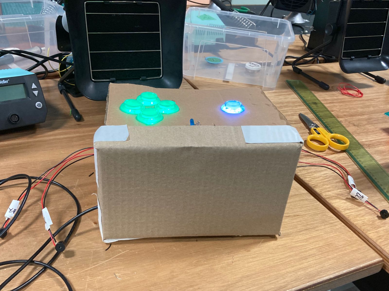
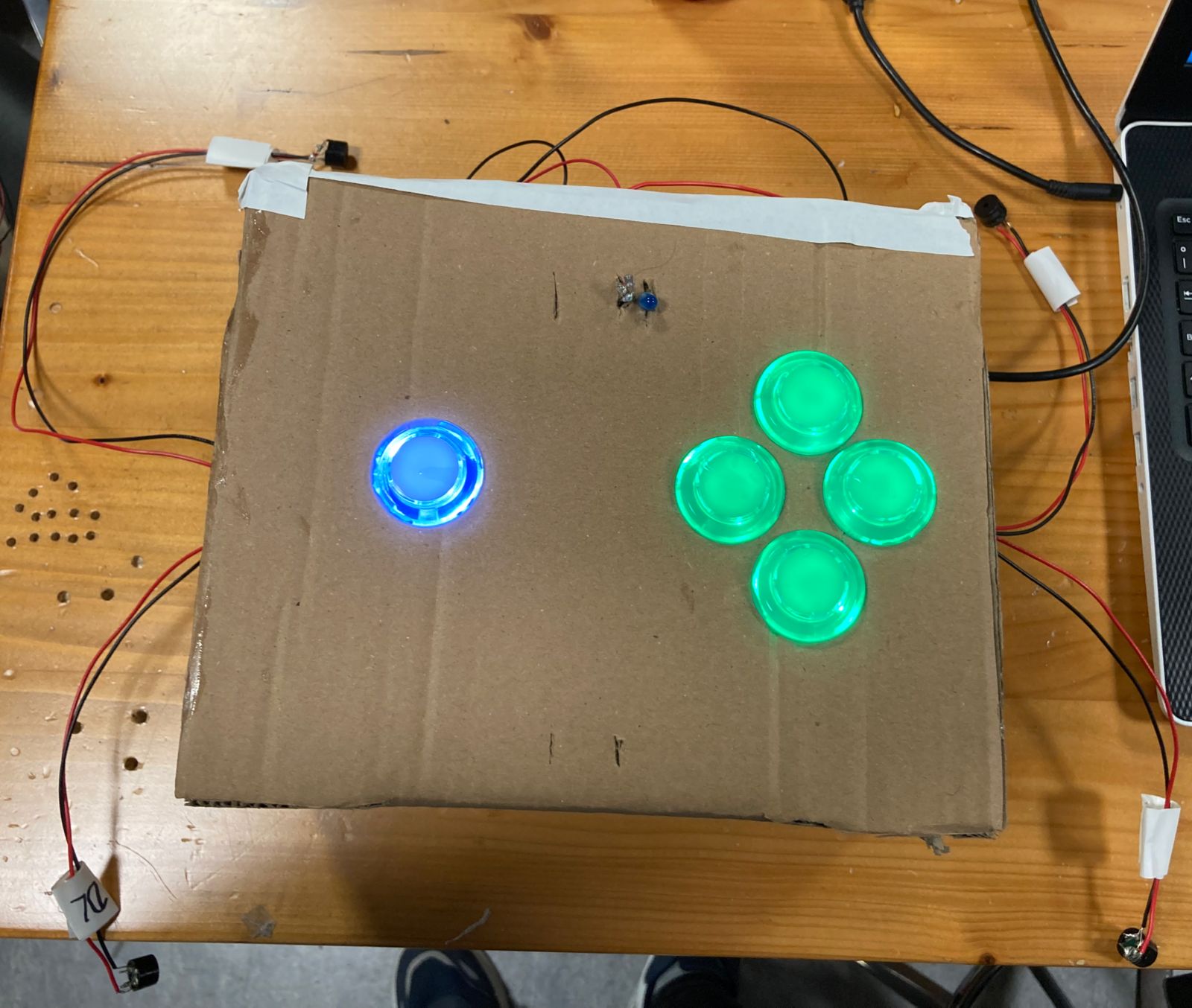
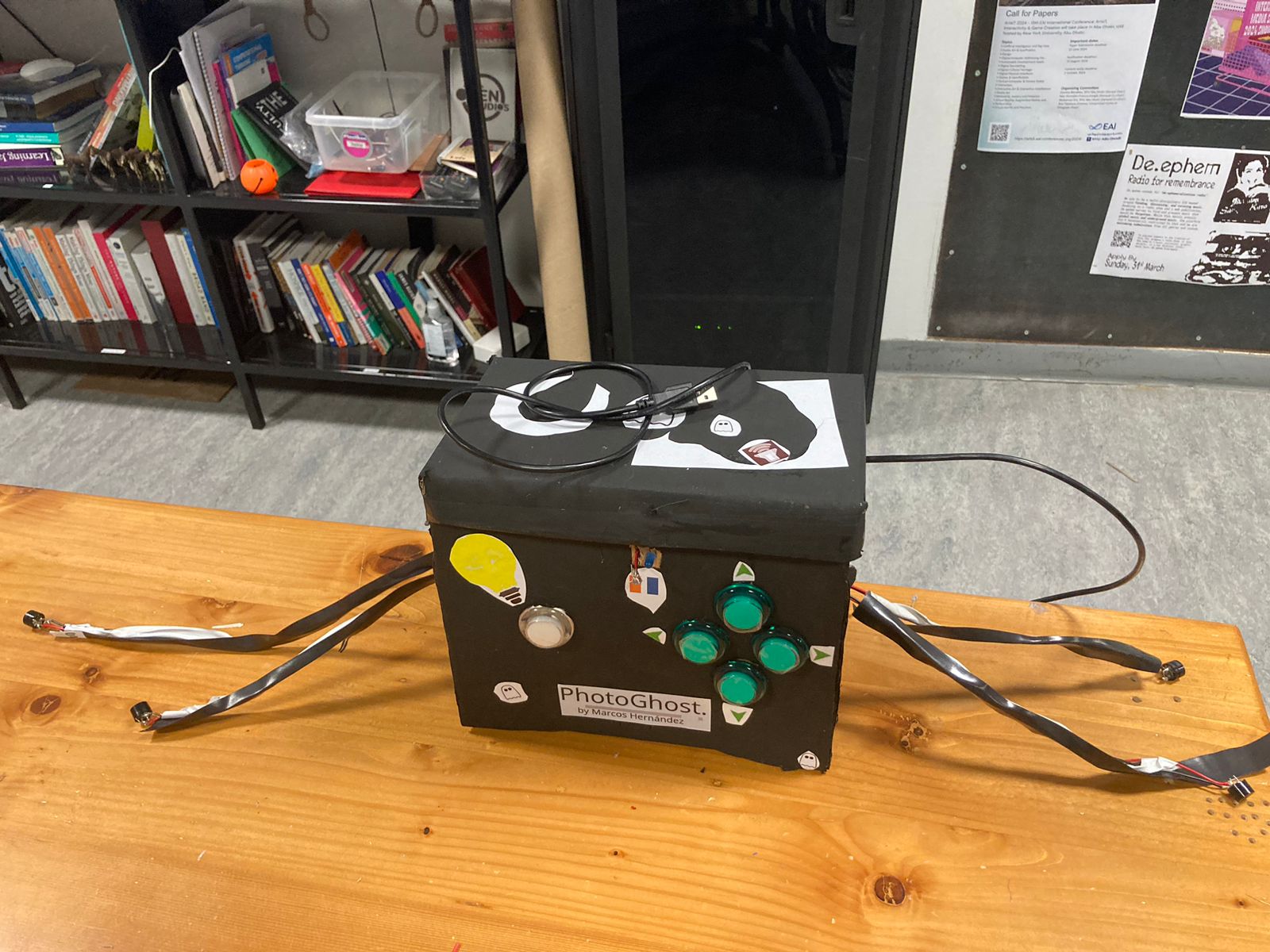
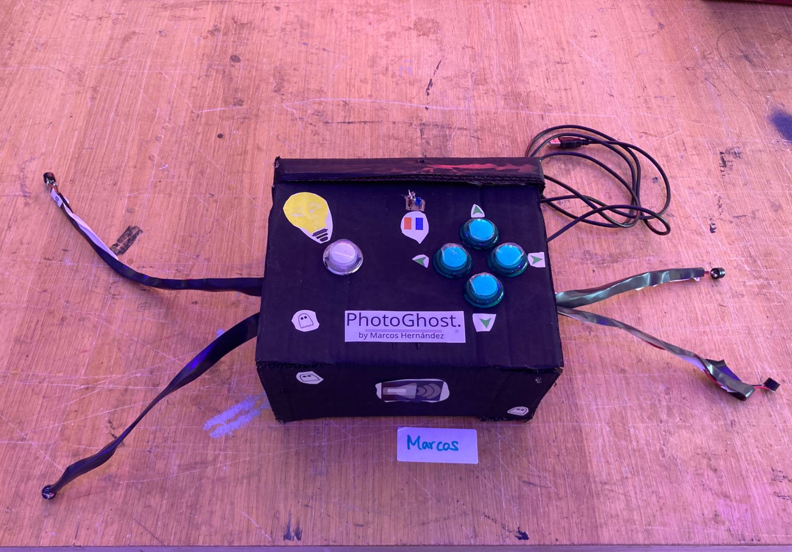
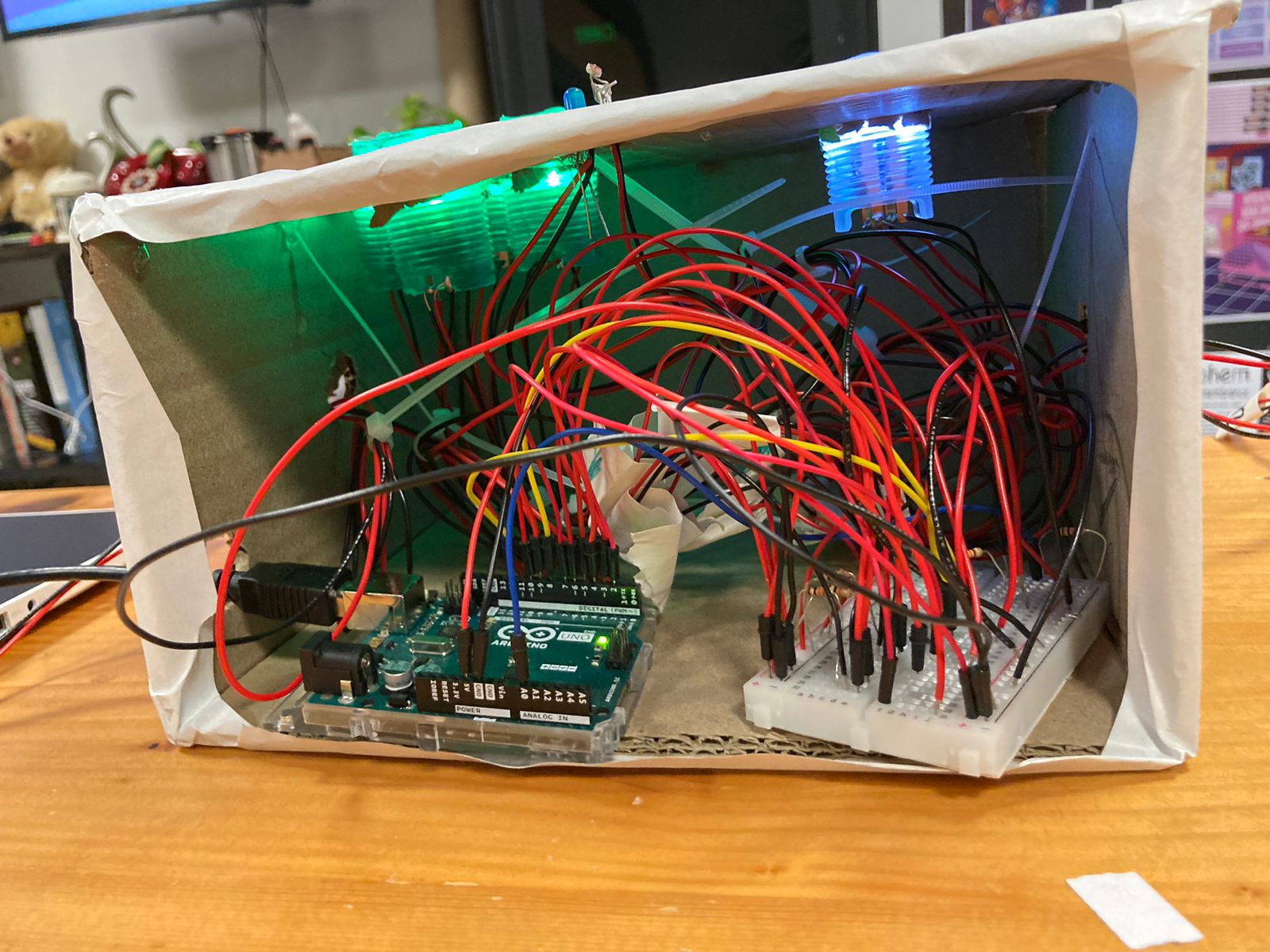
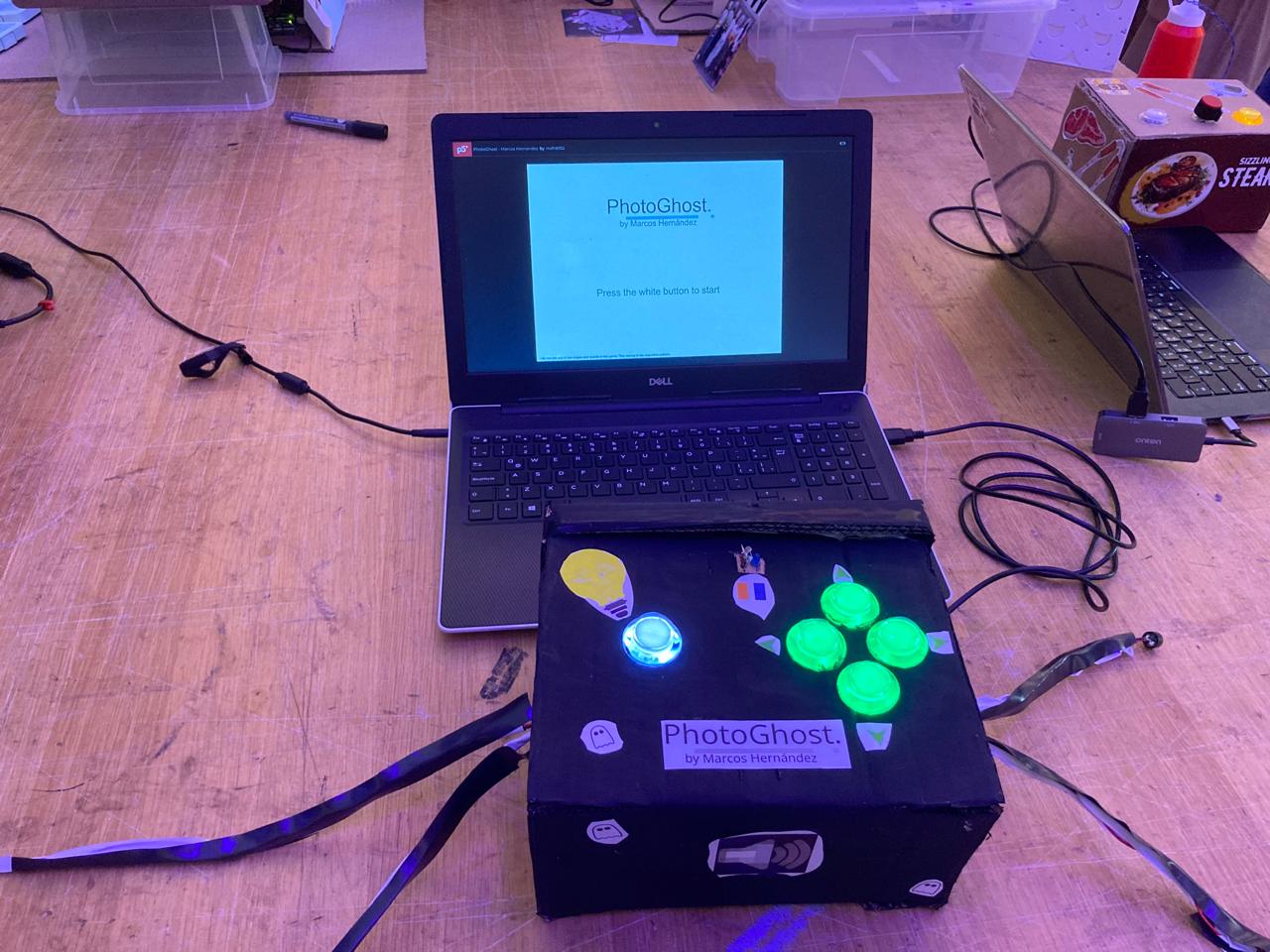
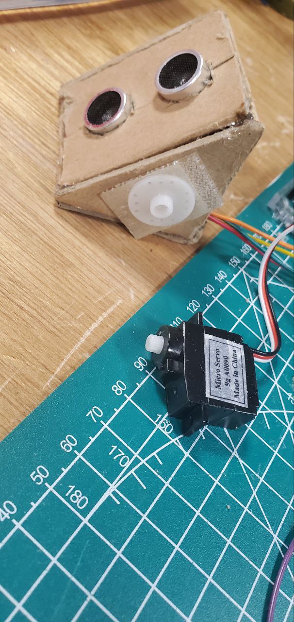
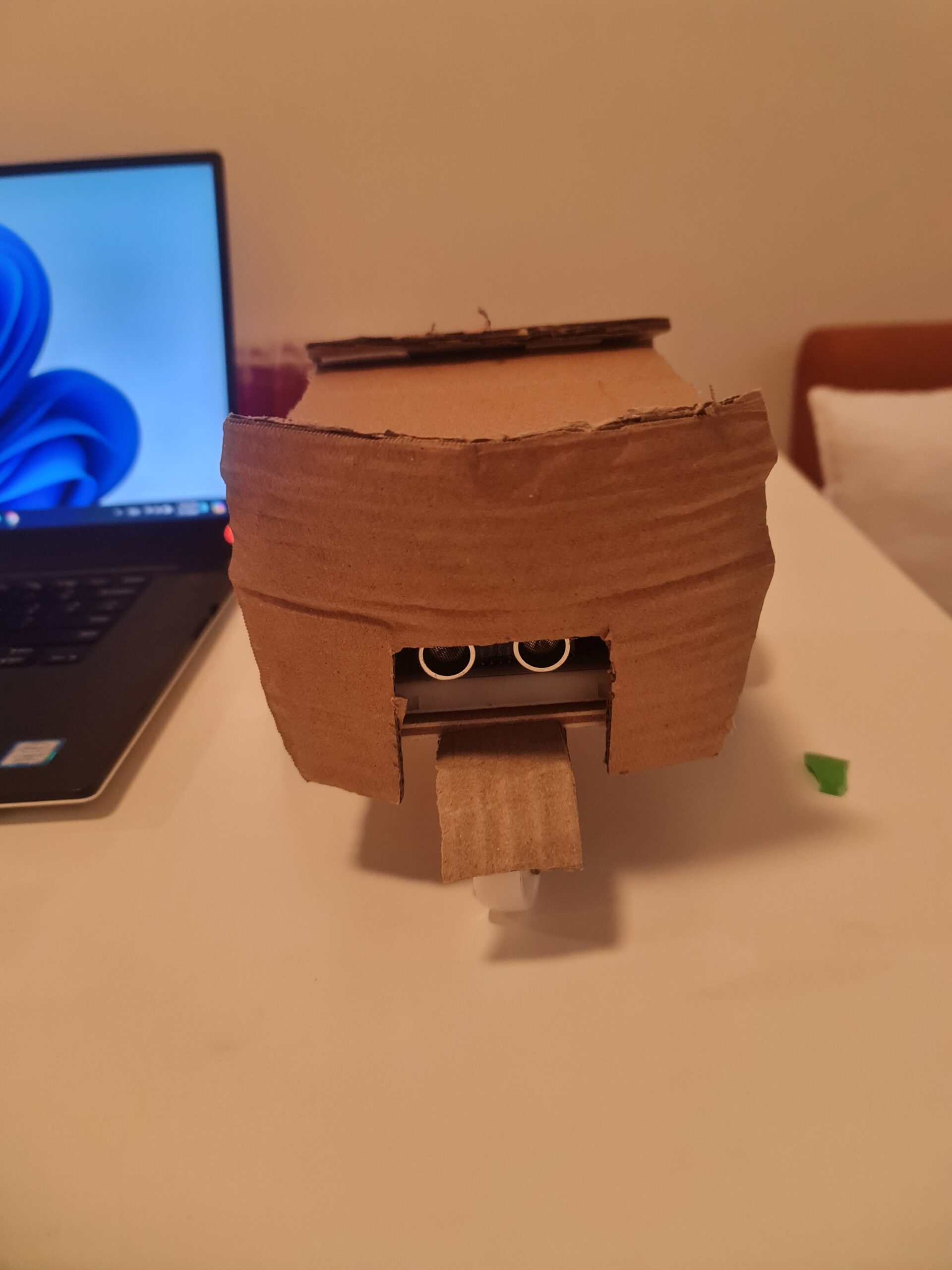
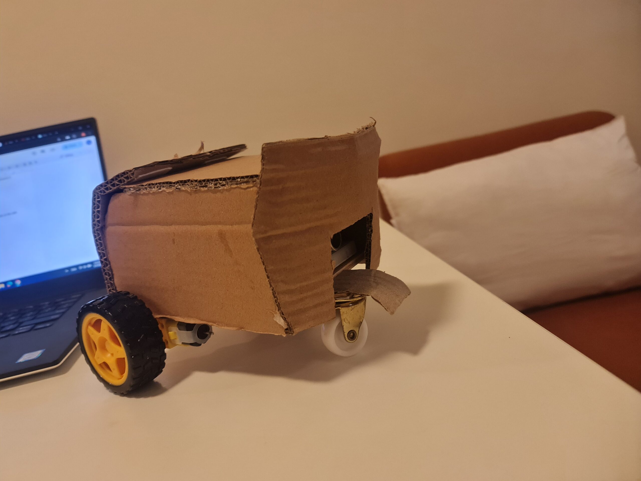
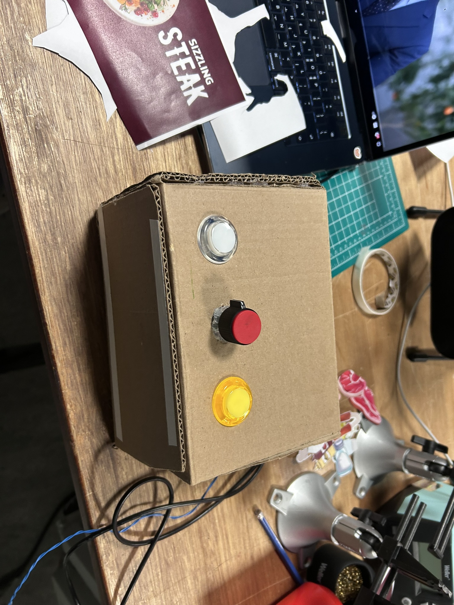
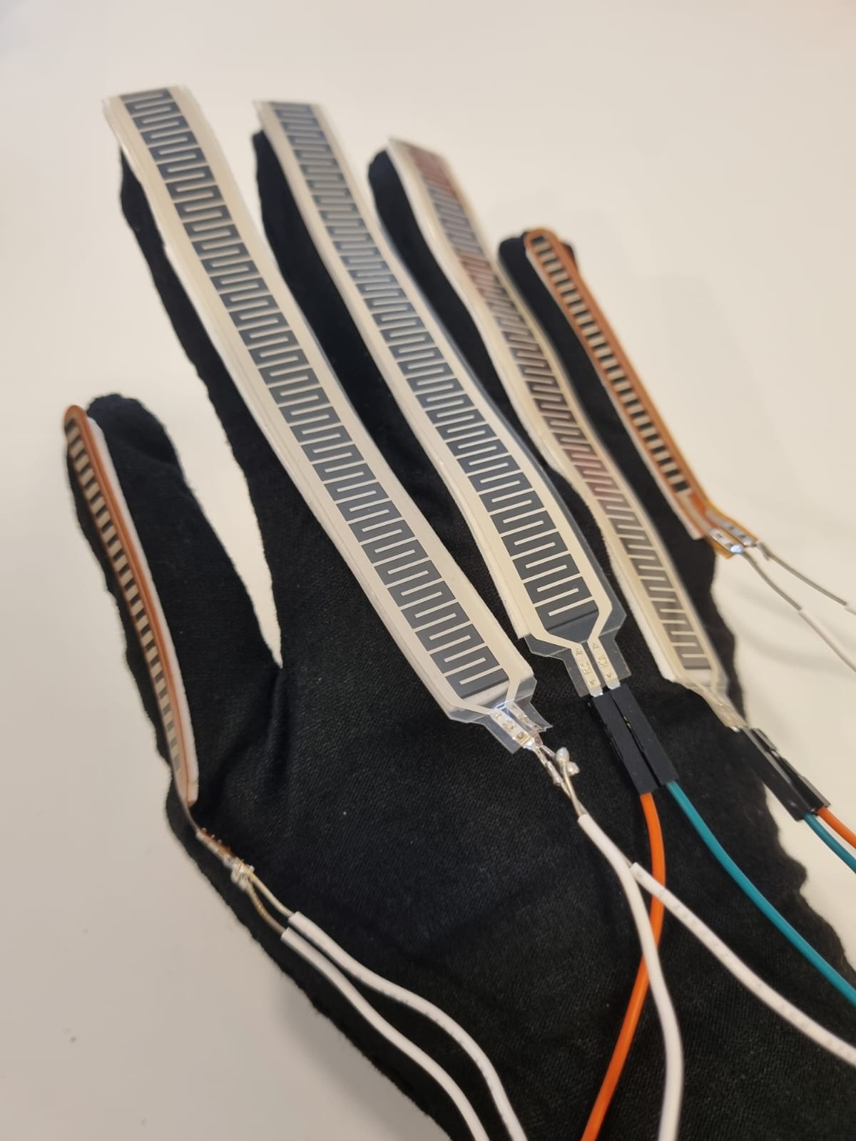
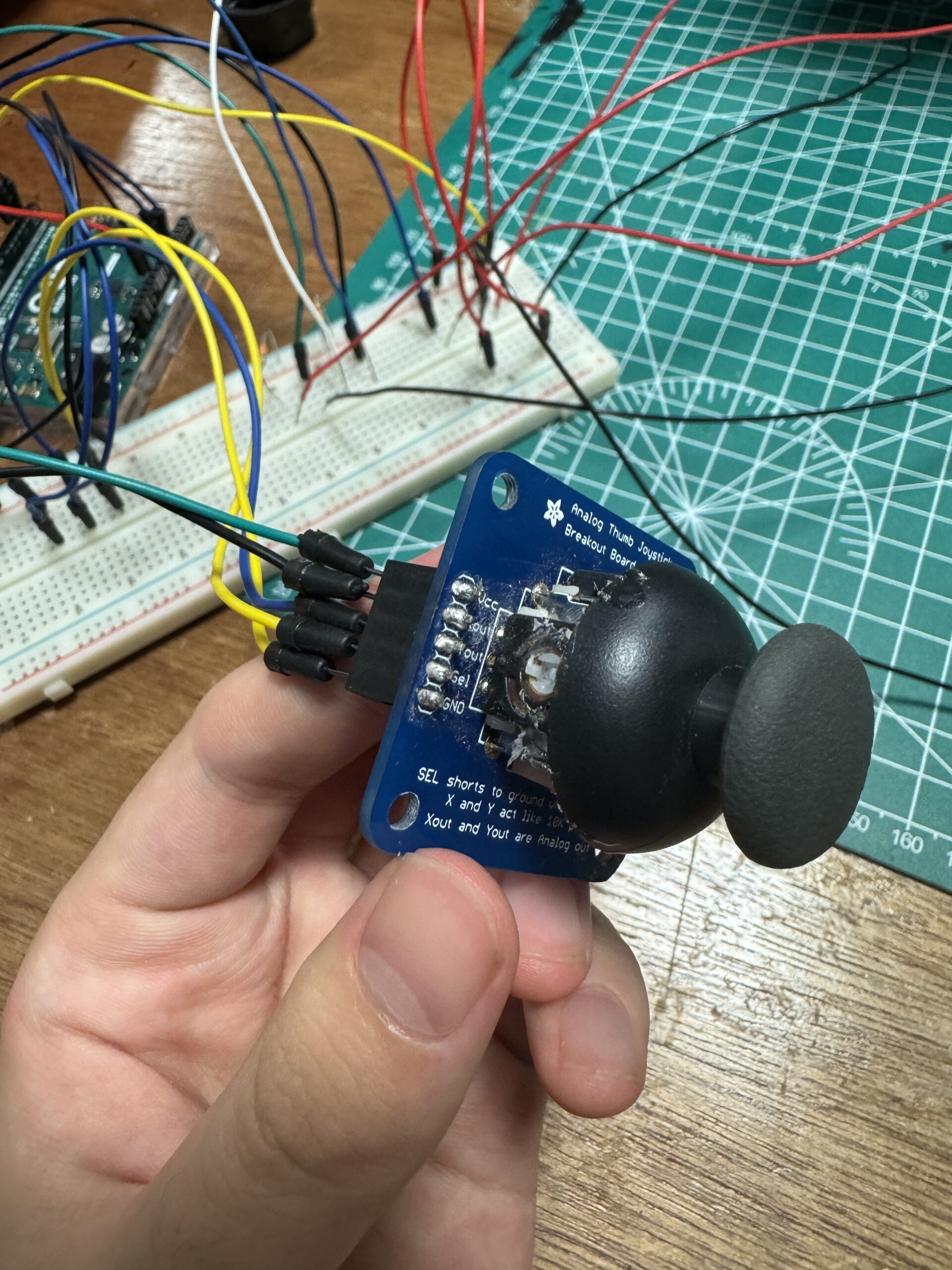
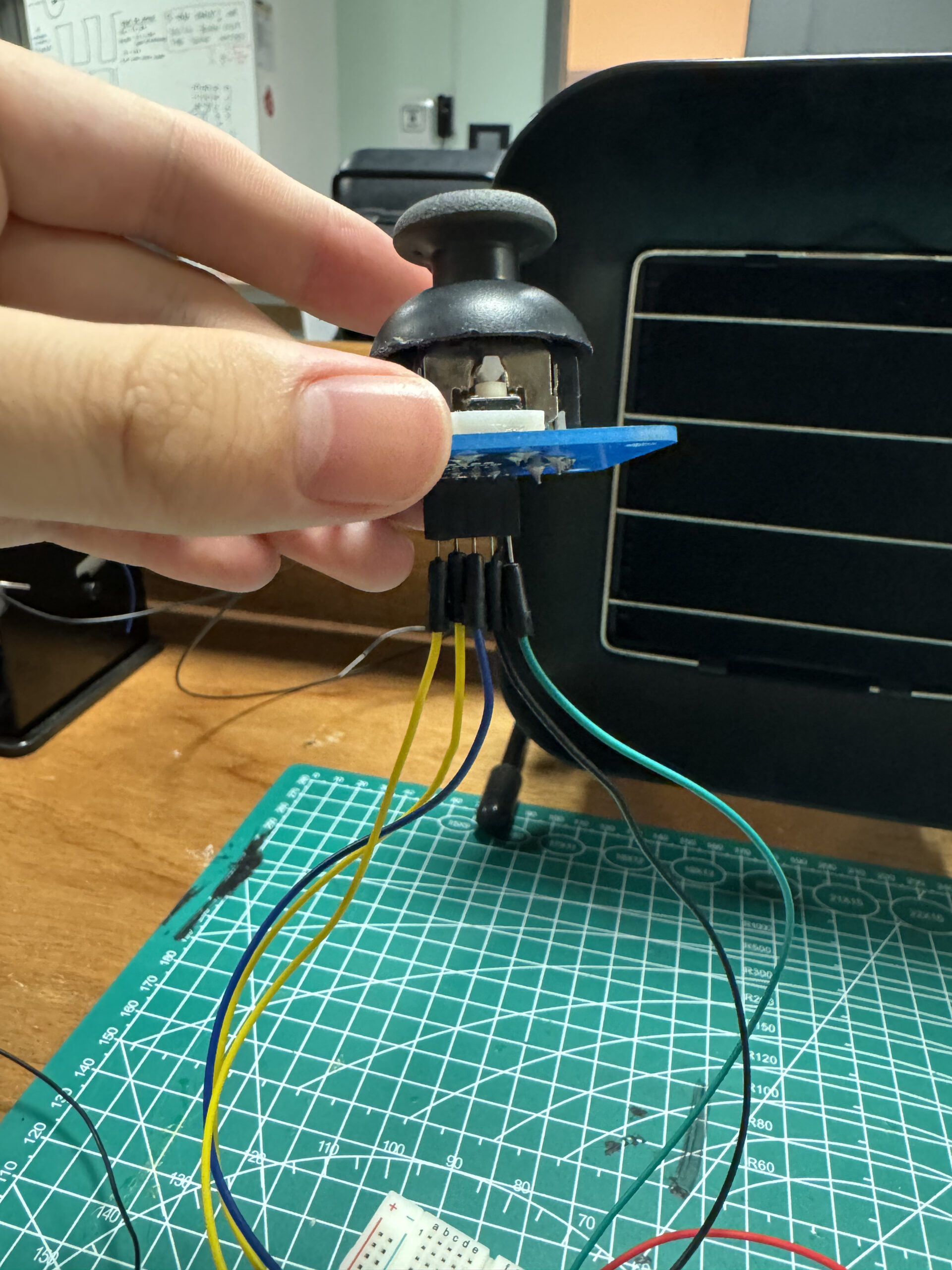
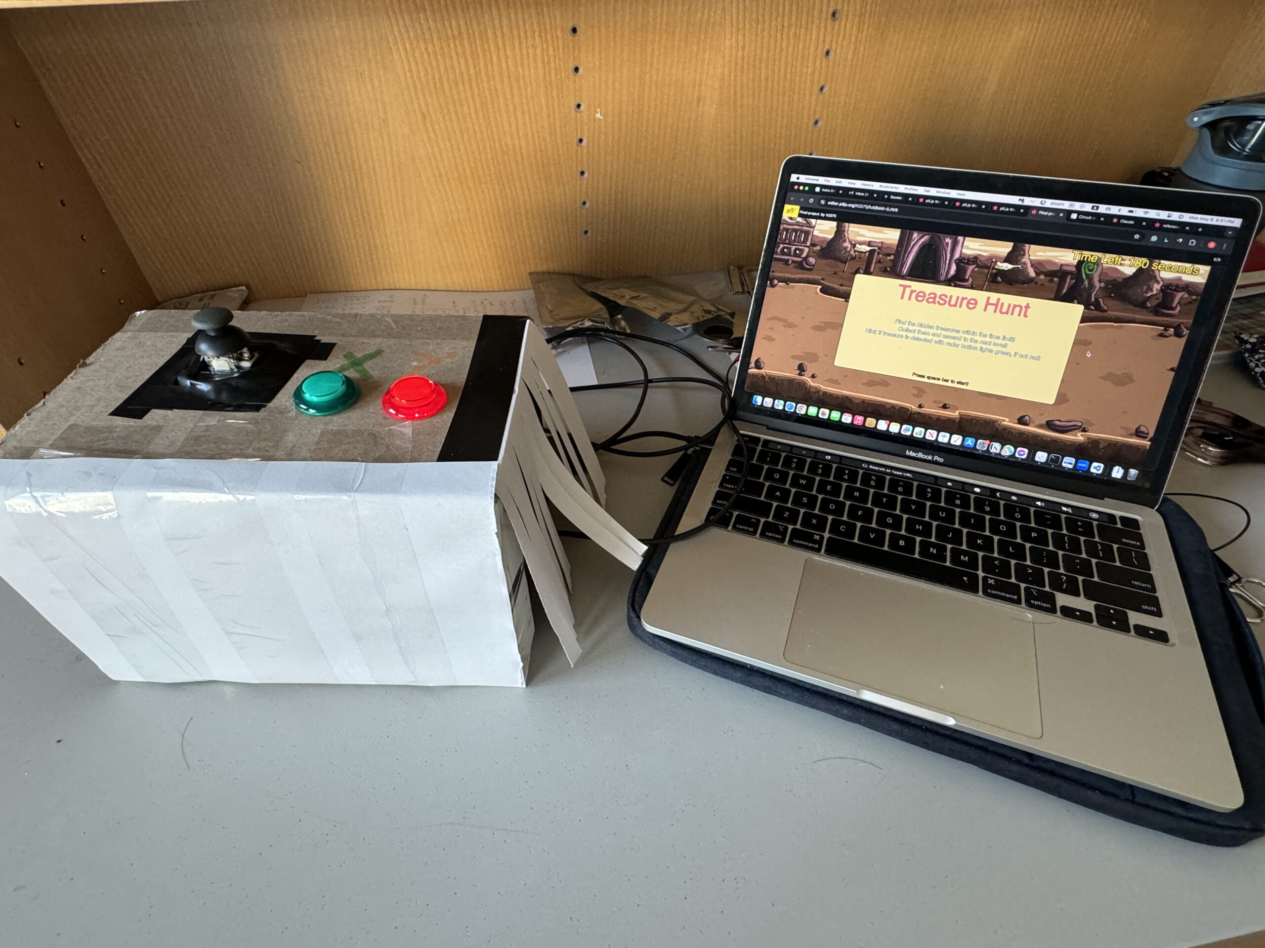
2.1 Picture of physical component
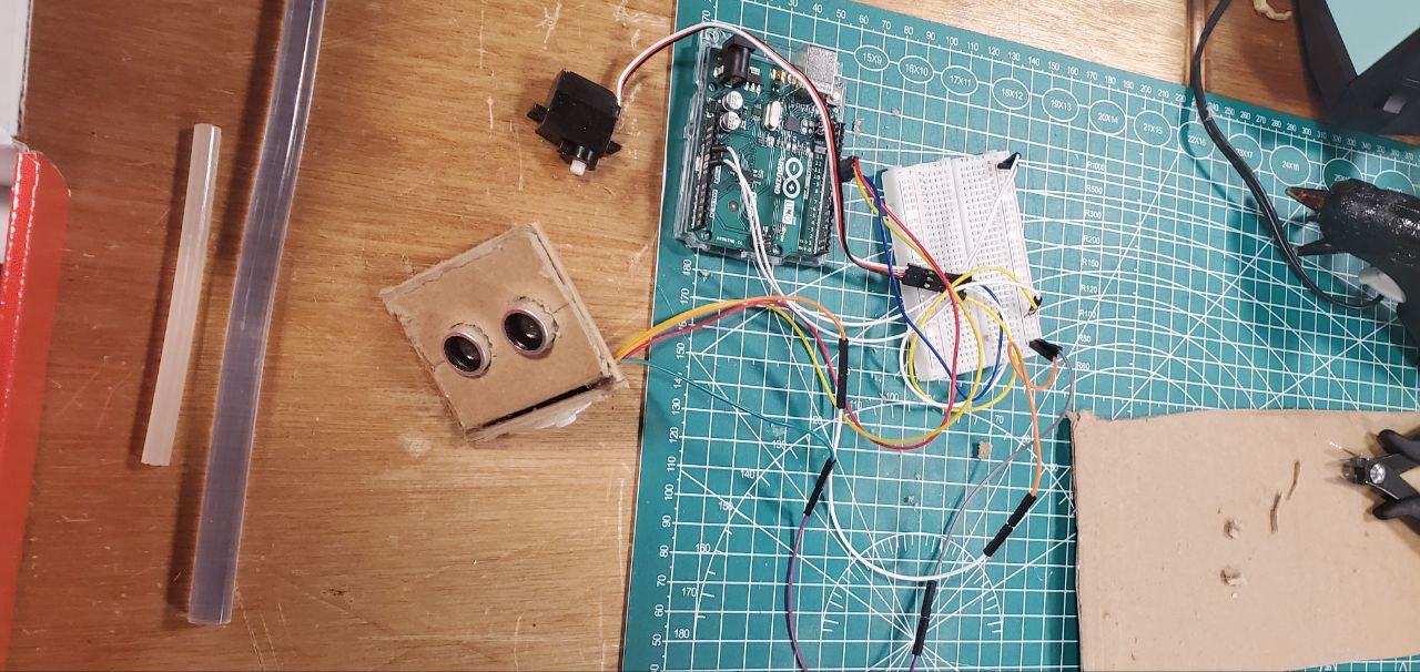
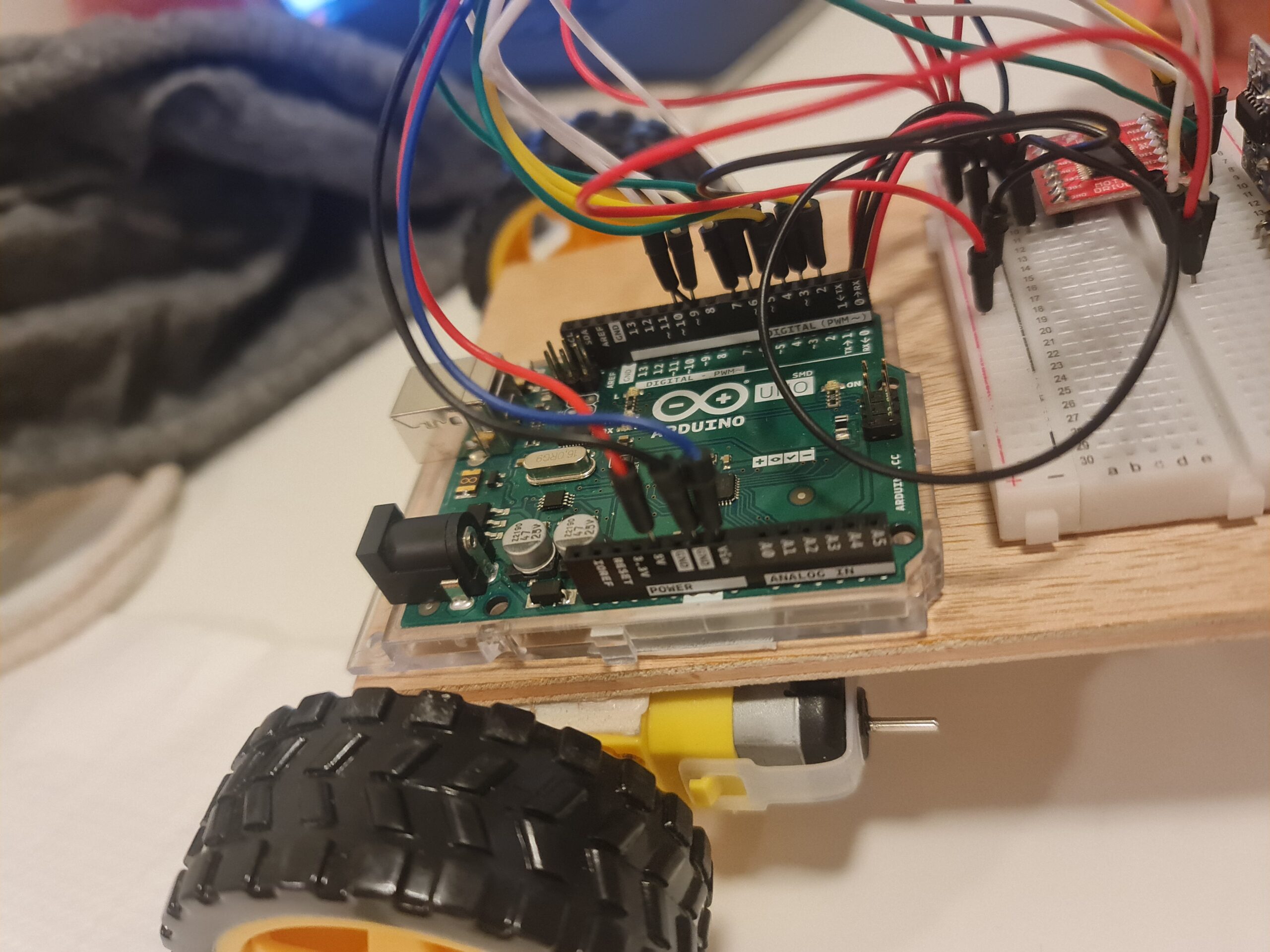
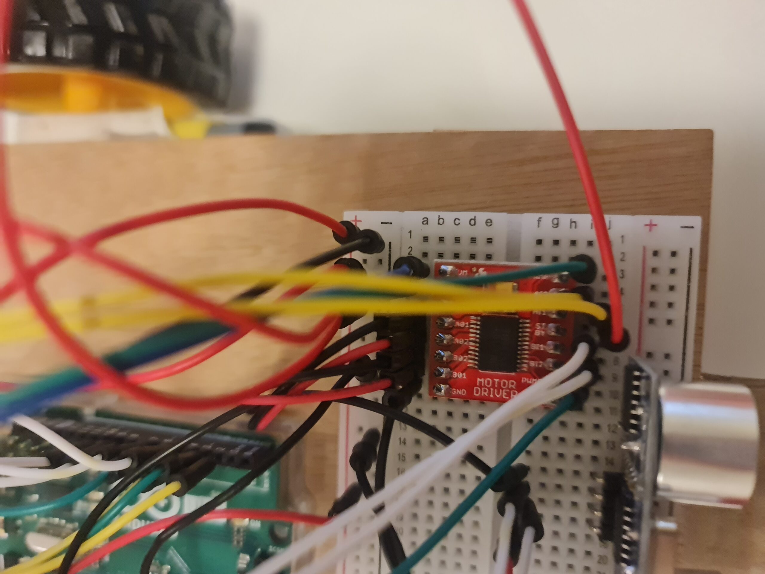
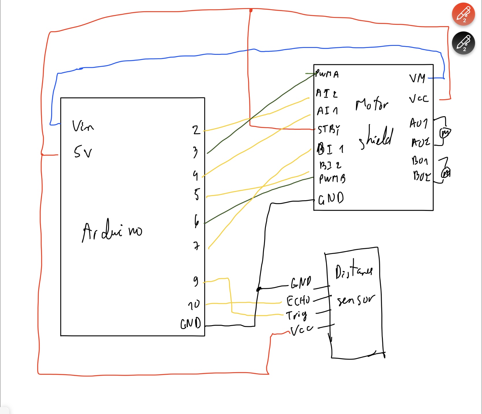
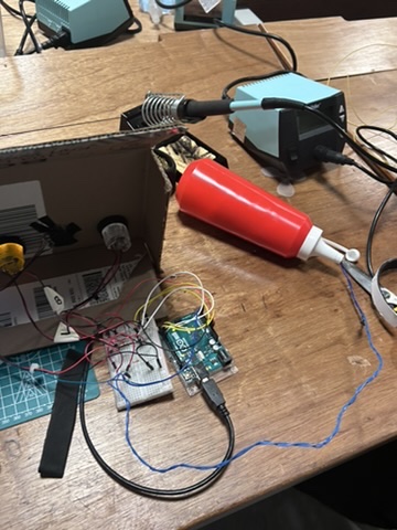
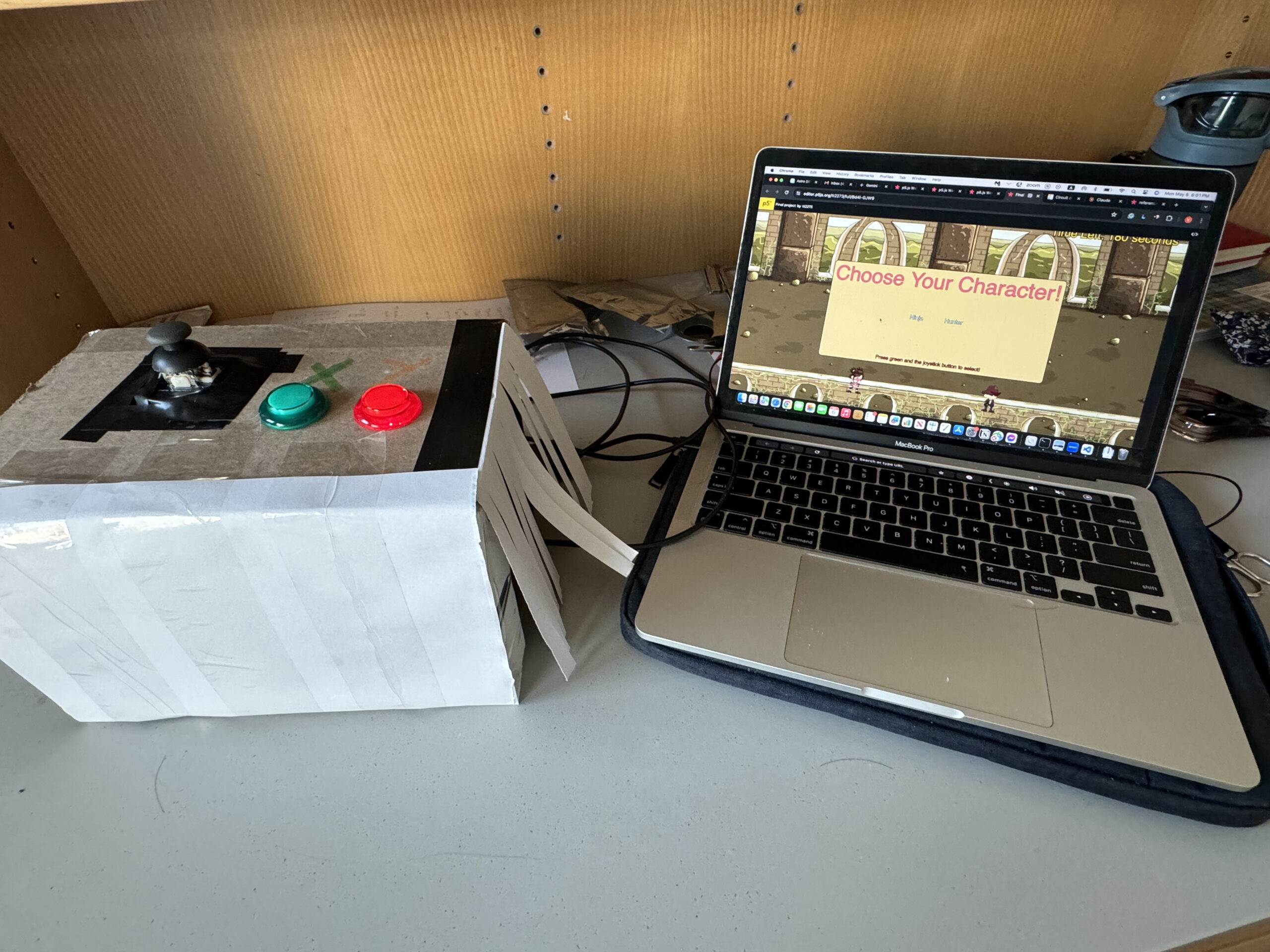
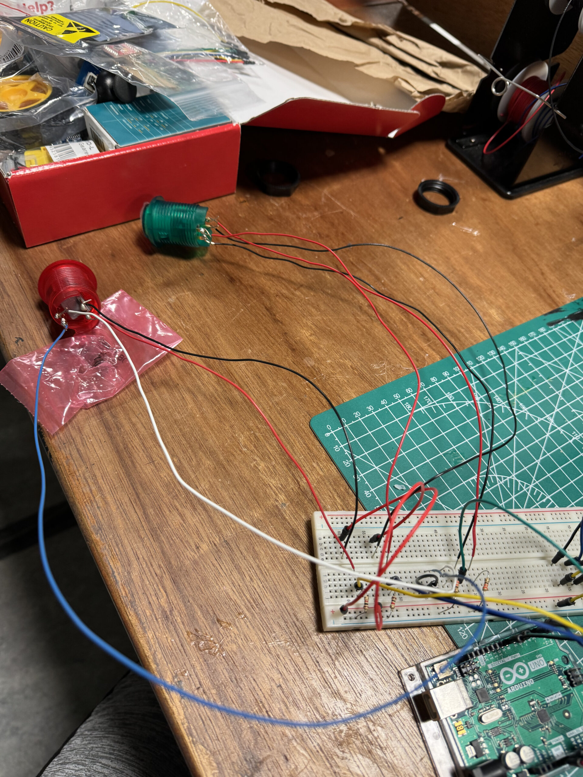
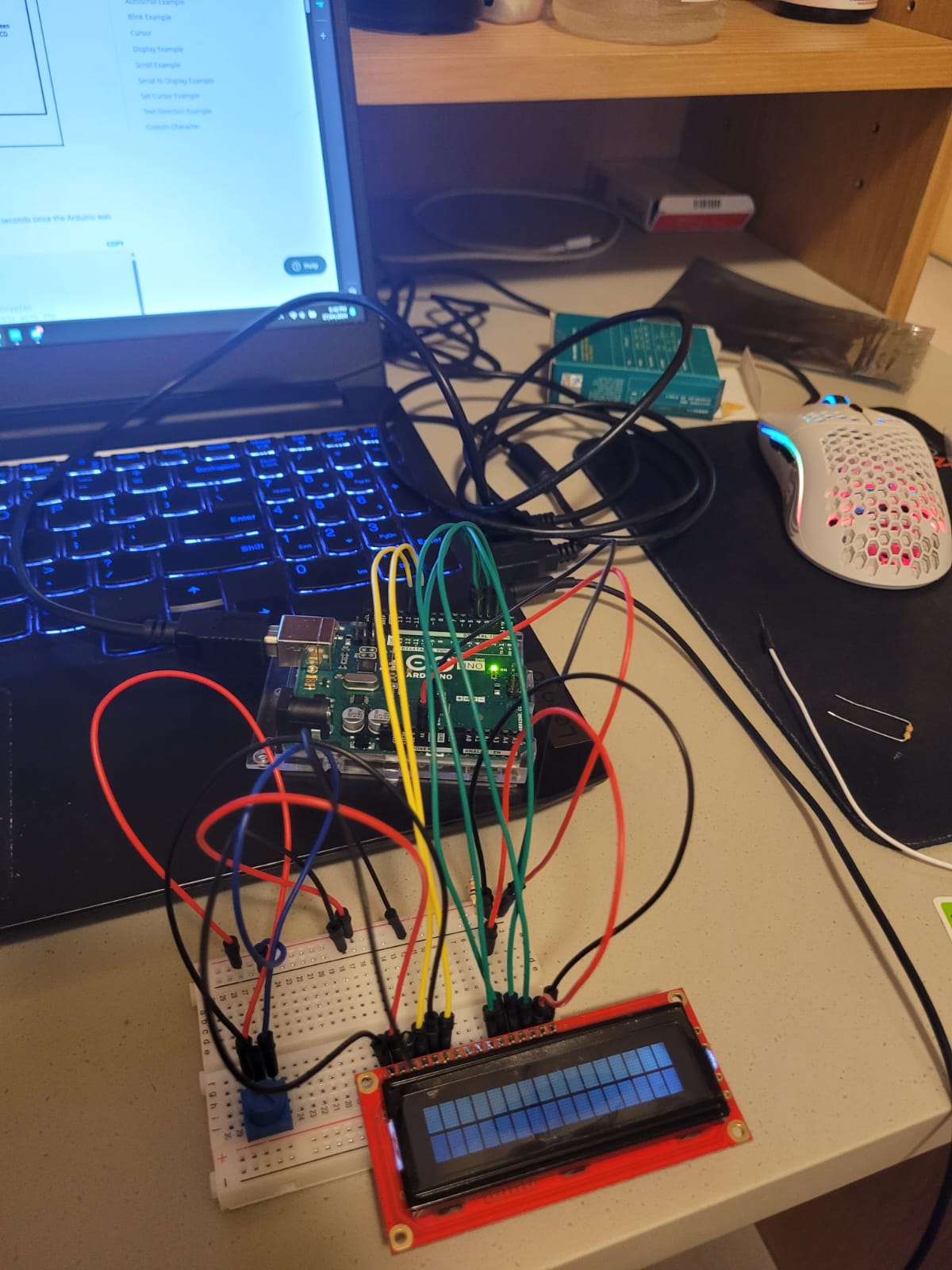
2.2 Pictures of the Arduino set-up
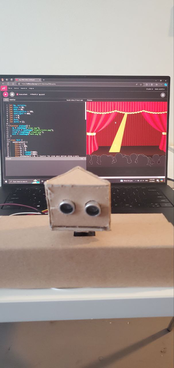
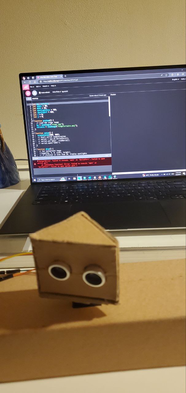
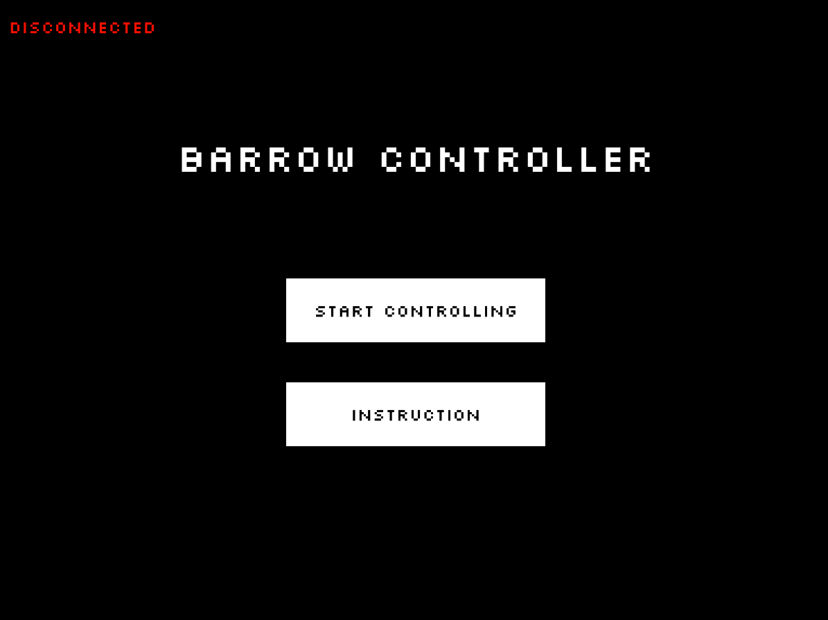
2.3 Pictures of the game in p5.js
3. Implementation
3.1. Interaction Design
When the player arrives at the controller, it will be observable that there are:
-
-
- 4 Green buttons placed as a D-PAD.
- One white button that is put further away from the rest of the components.
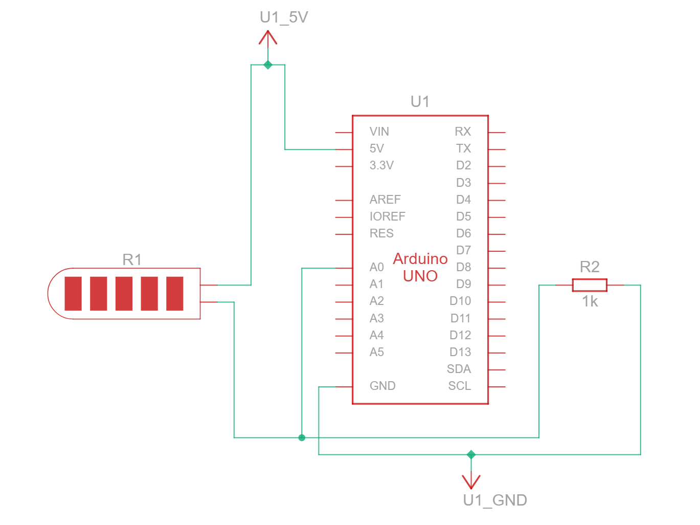
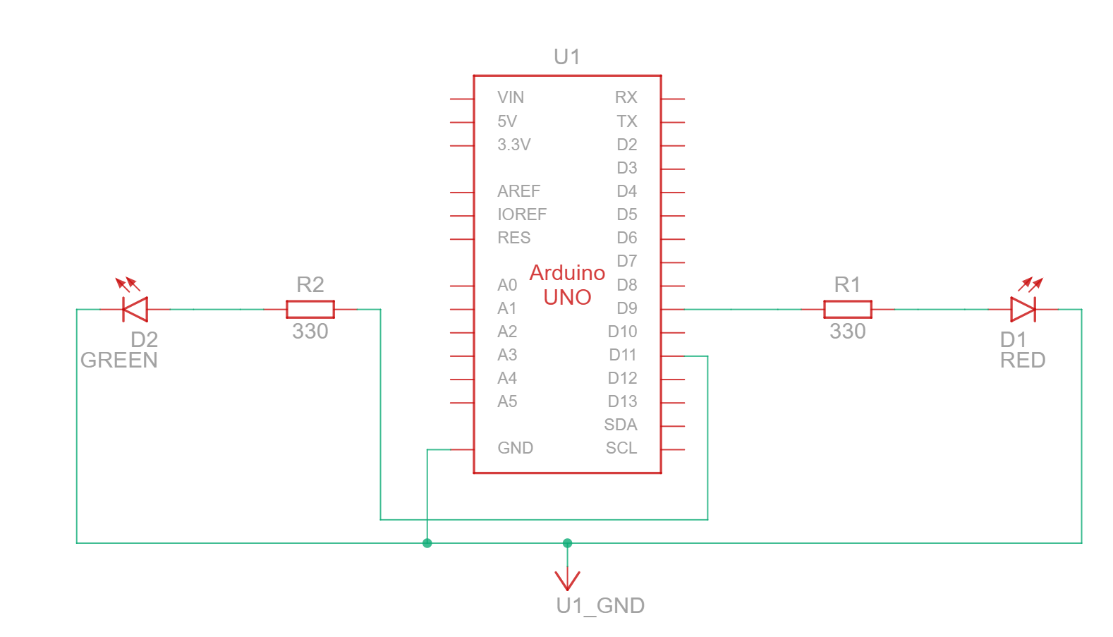
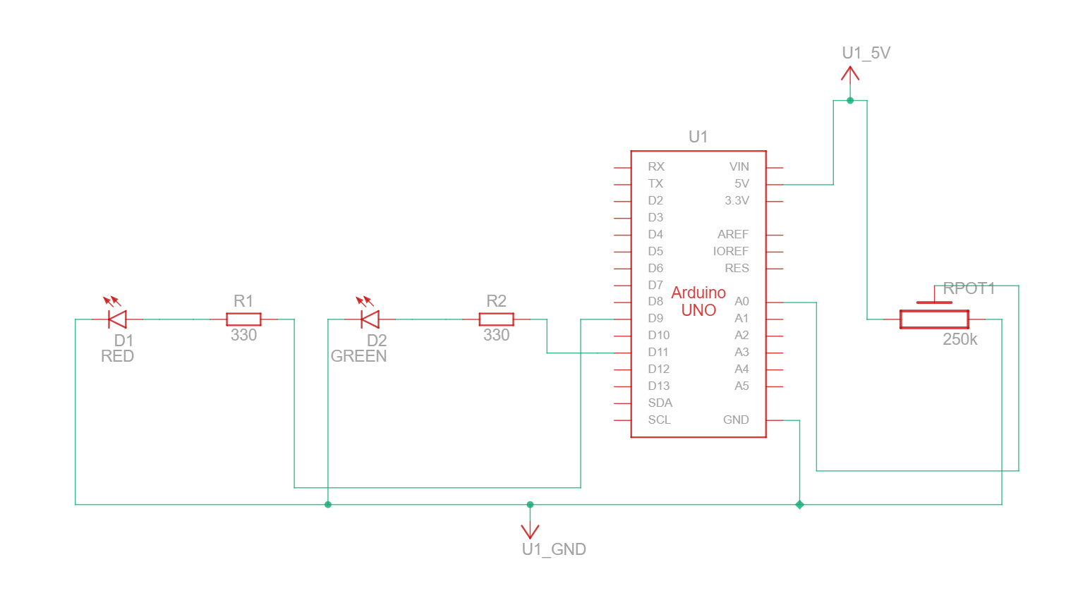
- One photoresistor and one blue LED close to each other.
- Four piezo buzzers that are coming on different sides: two on the left and two on the right. Each one is located on a different corner.
- A hole where the data is sent to the Arduino.
-
While the visual design is rather basic, it seeks to be portable, easy to read, and comfortable to use.
3.2. Description of Arduino code
Since the Arduino code is too long, here is a link to it on my GitHub: PhotoGhost. Arduino Code
Basically, what the Arduino code does is the following:
-
-
- It prepares the assigned pins, and then it waits to receive the communication with p5.js.
- Once communication is established, it starts reading the inputs of the green buttons (movement) and the white button (for the flashlight) in binary to check which is being pressed. Also, it checks for the current value of the flashlight, the location of the enemy, the assigned piezo speaker, and some controls (currentflashlightstatus and flashlightcountdown) to avoid sending data when it is not needed.
- Once it receives data from p5.js, it checks where the enemy is according to the value sent to the piezo speakers and plays a tune to indicate to the player the current position of the enemy.
if (SpiezoPinUL == 2) { tone(piezoPinUL, 500); } else if (SpiezoPinUL == 0) { noTone(piezoPinUL); } if (SpiezoPinUR == 2) { tone(piezoPinUR, 500); } else if (SpiezoPinUR == 0) { noTone(piezoPinUR); } if (SpiezoPinDL == 2) { tone(piezoPinDL, 500); } else if (SpiezoPinDL == 0) { noTone(piezoPinDL); } if (SpiezoPinDR == 2) { tone(piezoPinDR, 500); } else if (SpiezoPinDR == 0) { noTone(piezoPinDR); } - If the player is currently standing in a flashlight recharger, it starts reading the data coming from the photoresistor; this is done in this way to avoid exploits. At the same time, a blue LED is turned on, indicating that the photoresistor is receiving data.
- When finished, the photoresistor stops sending data, the blue LED is turned off, and it sends all the processed data to p5.js.
//I send you data and you send me more data!
Serial.print(brightness);
Serial.print(",");

//Flashlight
Serial.print(buttonFlashlight);
Serial.print(",");

//Movement
Serial.print(move_up);
Serial.print(",");
Serial.print(move_left);
Serial.print(",");
Serial.print(move_down);
Serial.print(",");
Serial.println(move_right);
-
3.3. Description of p5.js code and embedded example
The p5.js implementation was tricky. Before explaining the code, here is an embedded version of it. In the same embedded file, you can find the code for it:
Keep in mind that due to not having the Arduino control, it is possilbe to use WASD to move, F to turn the light ON and OFF, and BACKSPACE to skip the serial port screen.
In the p5.js code, the following is happening:
-
-
- The game first checks where the player is at the moment, whether it be the menu, the game over screen, or the gameplay. This is to arrange the code for better readability.
function draw() { if (gamestate == 0) { menu(); } else if (gamestate == 1) { game(); } else if (gamestate == 2) { credits(); } else if (gamestate == 3) { gameover(); } } - The game first waits for the player to set up the Arduino connection in order to start receiving input. This part of the code is inside the class file Menu.js:
display_mainmenu() { push(); background(250); fill(0); textSize(60); text("PhotoGhost.", 240, 150); textSize(25); text("by Marcos Hernández", 280, 190); textSize(10); text( "I do not own any of the images and sounds in this game. They belong to the respective authors.", 10, 595 ); fill(200); noStroke(); rect(300, 160, 230, 10); rect(570, 160, 10, 10); stroke(255); fill(0); textSize(30); if (!serialActive) { text("Press Space Bar to select serial port", 160, 400); } else { text("Press the white button to start", 200, 400); } pop(); } - Once the player finishes the tutorial by pressing the white button, they are immediately transported to the game. The timer starts, and every 60 frames, it adds a second, the flashlight battery gets reduced, and enemies are moved at set intervals. Also in this part, the game checks for multiple things, such as the random placement of the player, enemies, and the flashlight recharger. Here is an example of how it works with enemies:
if (time == 0 && enemyspawnercontrol == 0) {
    enemyspawnercontrol = 1;
    while (spawningenemy == true) {
      xtospawn = int(random(30, width));
      ytospawn = int(random(30, height));
      if (
        (xtospawn < player.x - 20 || xtospawn > player.x + player.w + 20) &&
        (ytospawn < player.y - 20 || ytospawn > player.y + player.h + 20)
      ) {
        enemy = new Enemies(xtospawn, ytospawn, 20, 20);
        enemies.push(enemy); //Add into the list of enemies.
        break;
      } else {
        //Nothing, it repeats lol.
      }
    }

    //Spawn enemy every 15 seconds.
  } else if (time % 15 == 0 && enemyspawnercontrol == 0) {
    enemyspawnercontrol = 1;
    while (spawningenemy == true) {
      xtospawn = int(random(30, width));
      ytospawn = int(random(30, height));
      if (
        (xtospawn < player.x - 20 || xtospawn > player.x + player.w + 20) &&
        (ytospawn < player.y - 20 || ytospawn > player.y + player.h + 20)
      ) {
        enemy = new Enemies(xtospawn, ytospawn, 20, 20);
        enemies.push(enemy); //Add into the list of enemies.
        break;
      } else {
        //Nothing, it repeats lol.
      }
    }
}
In a short explanation, the game first checks that the time is zero to spawn the first enemy in a location far from the player. Notice that a while loop is employed in order to avoid the enemy spawning accidentally inside the player and ending the game. After that, the enemy is saved into the array and displayed in order to be seen when the flashlight is ON.
- The player hitbox is divided into four parts, in a squarely manner, to check where the ghosts (enemies) are in order to send the current position of the ghost to the Arduino to play the sound to the corresponding piezo buzzer:
//Bottom right
    if (
      player.x + player.w * 5 > enemies[c].x &&
      player.x < enemies[c].x + enemies[c].w &&
      player.y + player.w * 5 > enemies[c].y &&
      player.y < enemies[c].y + enemies[c].w
    ) {
      SpiezoPinDR = 2;
      //print("FAR: Collision with bottom right.");
    }

    //Bottom left
    if (
      player.x - player.w * 5 + player.w * 5 > enemies[c].x &&
      player.x - player.w * 5 < enemies[c].x + enemies[c].w &&
      player.y + player.w * 5 > enemies[c].y &&
      player.y < enemies[c].y + enemies[c].w
    ) {
      SpiezoPinDL = 2;
      //print("FAR: Collision with bottom left.");
    }

    //Upper right
    if (
      player.x + player.w * 5 > enemies[c].x &&
      player.x < enemies[c].x + enemies[c].w &&
      player.y - player.w * 5 + player.w * 5 > enemies[c].y &&
      player.y - player.w * 5 < enemies[c].y + enemies[c].w
    ) {
      SpiezoPinUR = 2;
      //print("FAR: Collision with Upper right.");
    }

    //Upper left
    if (
      player.x - player.w * 5 + player.w * 5 > enemies[c].x &&
      player.x - player.w * 5 < enemies[c].x + enemies[c].w &&
      player.y - player.w * 5 + player.w * 5 > enemies[c].y &&
      player.y - player.w * 5 < enemies[c].y + enemies[c].w
    ) {
      SpiezoPinUL = 2;
      //print("FAR: Collision with Upper left.");
    }
  }
5. Inputs are processed when they are mapped from the data received from Arduino with the following function:
function checkMovementPlayer() {
  //Check if the button is still pressed and if the player is dead.
  if (buttonnotpressed == 0 && player.dead != 1) {
    if (move_right == 1 && player.x < width - 60) {
      player.x += 40;
      buttonnotpressed = 1;
    }

    if (move_left == 1 && player.x > 40) {
      player.x -= 40;
      buttonnotpressed = 1;
    }

    if (move_down == 1 && player.y < height - 40) {
      player.y += 40;
      buttonnotpressed = 1;
    }

    if (move_up == 1 && player.y > 40) {
      player.y -= 40;
      buttonnotpressed = 1;
    }

    //Check if all buttons are not pressed in order to rehabilitate the button pressing.
  } else if (
    move_right == 0 &&
    move_left == 0 &&
    move_down == 0 &&
    move_up == 0
  ) {
    buttonnotpressed = 0;
  }
}
It is made in this way to only allow one input at a time that does not repeat, at least for the green buttons. Since if the button is held, it will send many HIGH (1) values to move into the corresponding position. This can cause many troubles when moving, so the variable buttonnotpressed is implemented to only allow one input. The flashlight can be held.
- Lastly, the game checks if the game ended via the player either colliding with a ghost, which is checked with the hitbox, or if the player ran out of battery.
- The game first checks where the player is at the moment, whether it be the menu, the game over screen, or the gameplay. This is to arrange the code for better readability.
-
This is a brief summary, as there are more things happening in the backend, but there are the most relevant functions.
3.4. Description of communication between Arduino and p5.js
Arduino and p5.js communicate in the following way, in the following order:
-
-
- As previously mentioned, Arduino waits for p5.js to send the data in order to send and receive data.
- Once communication is established, p5.js checks for any input coming from Arduino, and it is the same in Arduino’s part, and both sides map this information:Arduino code for receiving the data and mapping it:
value = Serial.parseInt();  //We read the value here.

SpiezoPinUL = Serial.parseInt();  //We read the values of the piezos here.
SpiezoPinUR = Serial.parseInt();
SpiezoPinDL = Serial.parseInt();
SpiezoPinDR = Serial.parseInt();

currentflashlightstatus = Serial.parseInt();

flashlightcountdown = Serial.parseInt();
Arduino code sending:
//I send you data and you send me more data!
Serial.print(brightness);
Serial.print(",");

//Flashlight
Serial.print(buttonFlashlight);
Serial.print(",");

//Movement
Serial.print(move_up);
Serial.print(",");
Serial.print(move_left);
Serial.print(",");
Serial.print(move_down);
Serial.print(",");
Serial.println(move_right);
p5.js code (Receiving, as in mapping, and sending):
function readSerial(data) {
  //First battery gets sent, then the rest of the values of the buzzers, and finally the current status of the flashlight.
  if (data != null) {
    let arduinoReceivedData = split(trim(data), ",");

    //Check if it is the right length to then process the data.
    if (arduinoReceivedData.length == 6) {
      chargingvalue = int(arduinoReceivedData[0]);
      buttonFlashlight = int(arduinoReceivedData[1]);
      move_up = int(arduinoReceivedData[2]);
      move_left = int(arduinoReceivedData[3]);
      move_down = int(arduinoReceivedData[4]);
      move_right = int(arduinoReceivedData[5]);
    }
    //print(arduinoReceivedData);

    //Collect brigthness value to charge it.
  }

  let sendToArduino =
    int(hud.currentbattery) +
    "," +
    SpiezoPinUL +
    "," +
    SpiezoPinUR +
    "," +
    SpiezoPinDL +
    "," +
    SpiezoPinDR +
    "," +
    int(flashlight.statusflashlight) +
    "," +
    int(flashlight.insideflashlightcharger) +
    "\n";

  writeSerial(sendToArduino); //Send
}
3. After both parts receive this data, they perform the corresponding actions as mentioned in the respective sections of both codes.
-
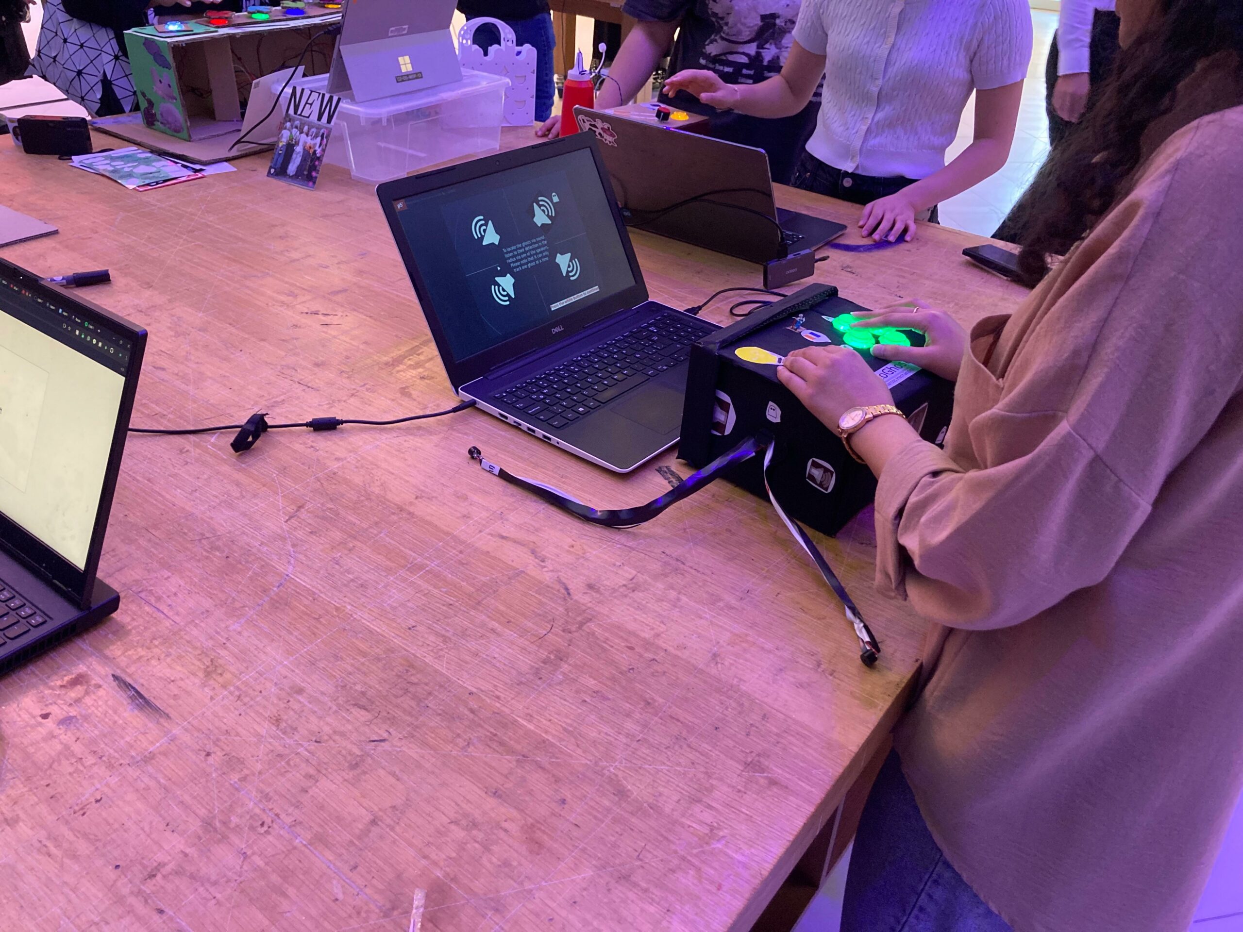
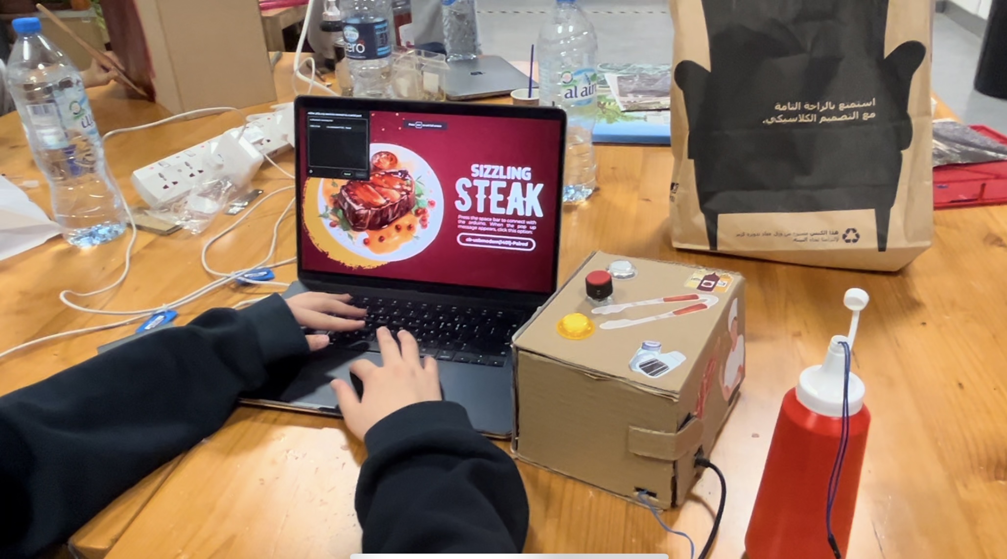
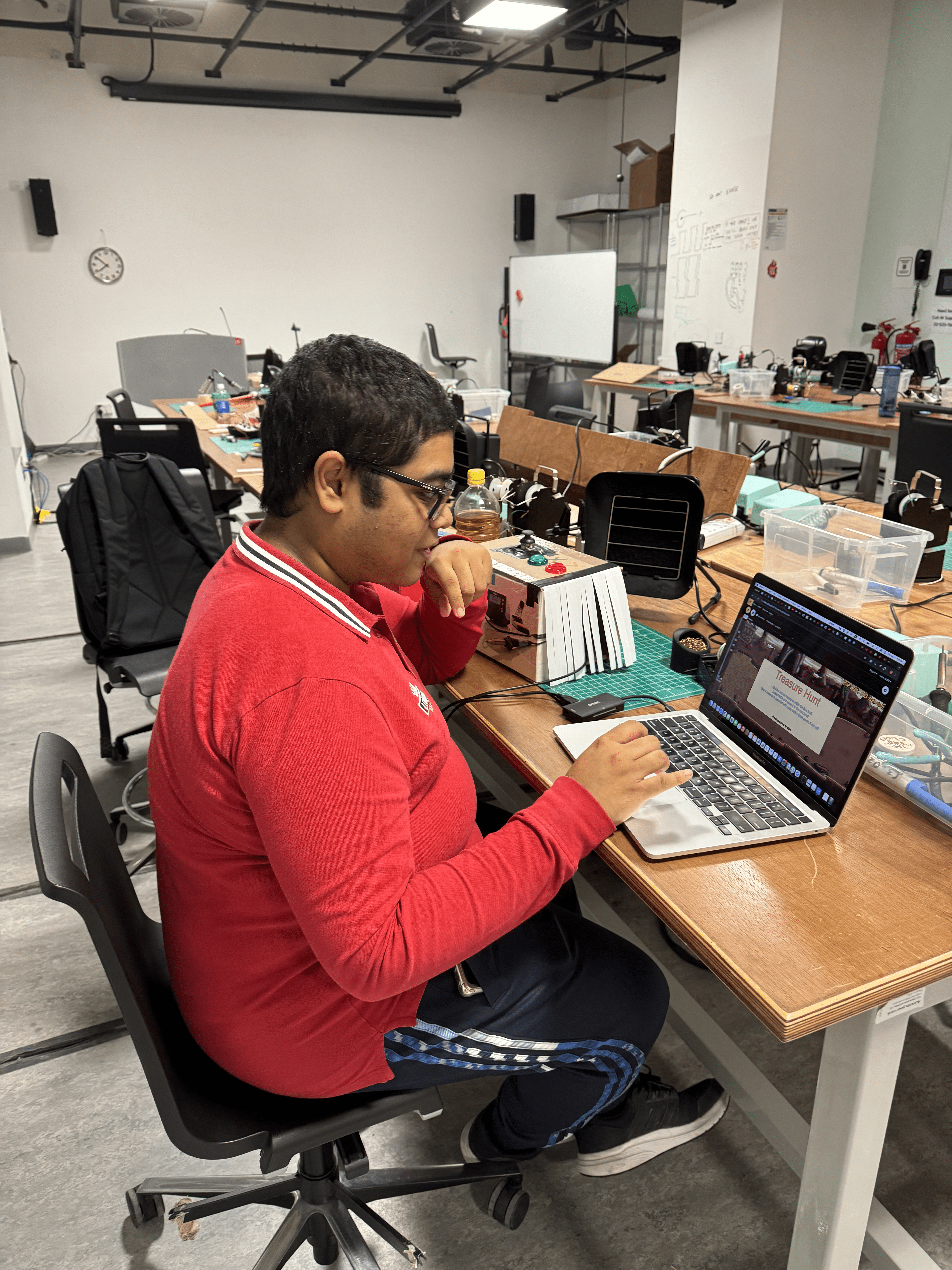
4. User testing video
Here is a video for the user testing, it was done without making any comment or question to the player:
What was interesting is that the player did not noticed that the flashlight button could be used in gameplay until the last portion of the video. Therefore, I should start thinking in a solution for this.
5. Aspects I am proud of
I am proud that, for the first time in my life, I could work with my hands to a higher level. I am not used to soldering, wiring, and making code for serial communication, it was a challenge, but the fact that I could improve on it makes me more than happy.
As for the code, it was not really a challenge since the project that I did for the midterm was significantly harder to do, so the initial implementation was easy. Although, when it comes to the loop of receiving data from Arduino and sending it, that is where the troubles happened. Again, I am happy that I could figure out the physical and programming part, it took a lot of time and all-nighters, but at the end, it was helpful in improving my programmer skills.
6. Future improvements
I would like to improve the following aspects:
-
-
- Better tutorial, since players do not use the flashlight function that much.
- Improve the graphics, since they are rather simplistic.
- Improve audio detection of the ghosts.
- Add a physical layout to the game to increase the variety of outcomes.
- Improve the wiring of the Arduino.
- Improve the design of the box which is used to interact with the game.
-
With that said, I am satisfied with the end results as they are.
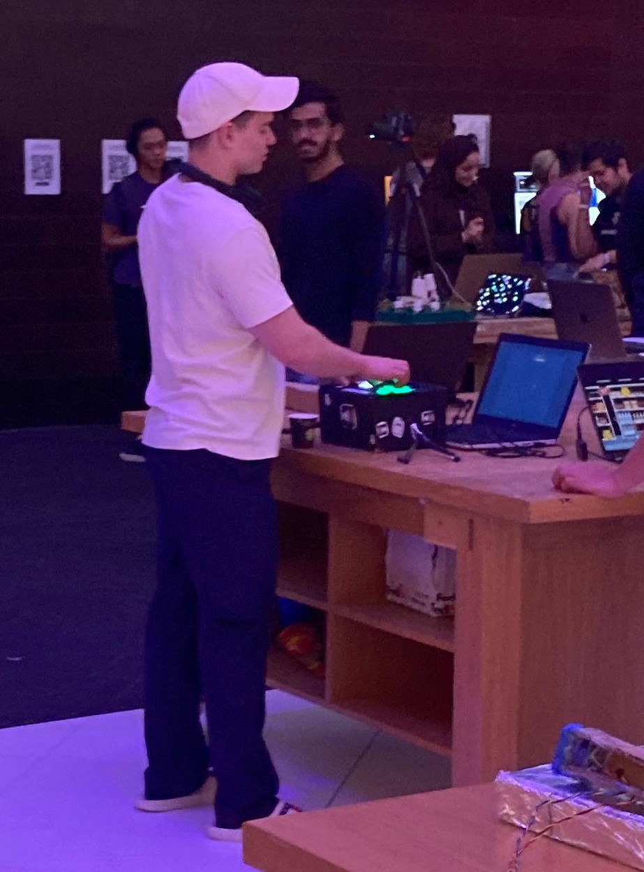
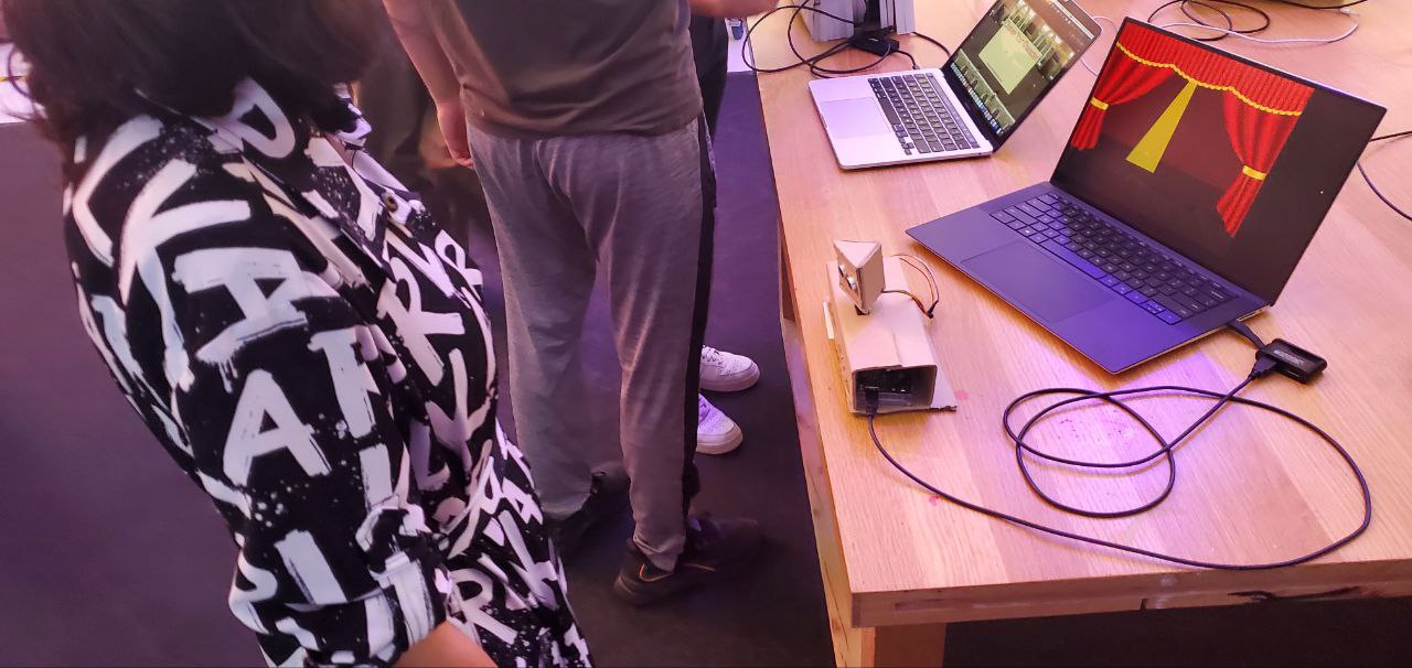
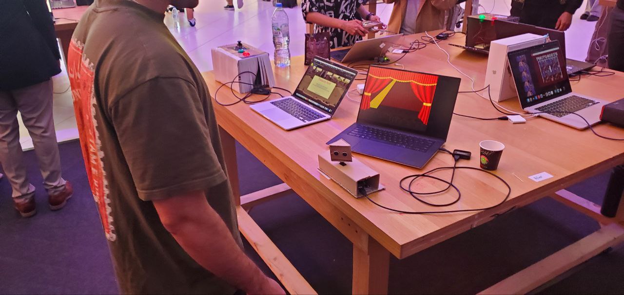
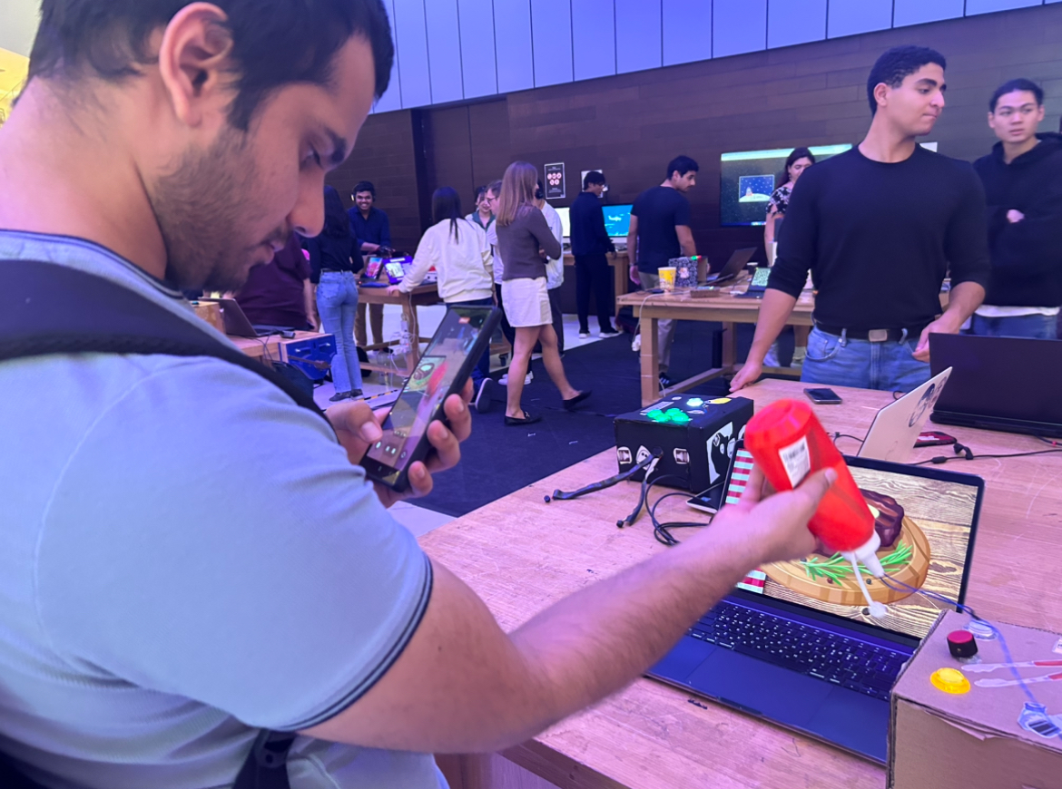
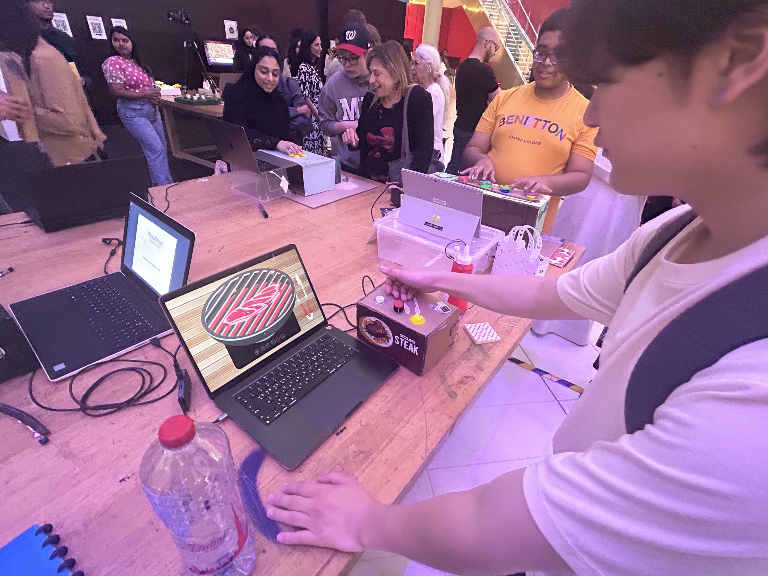
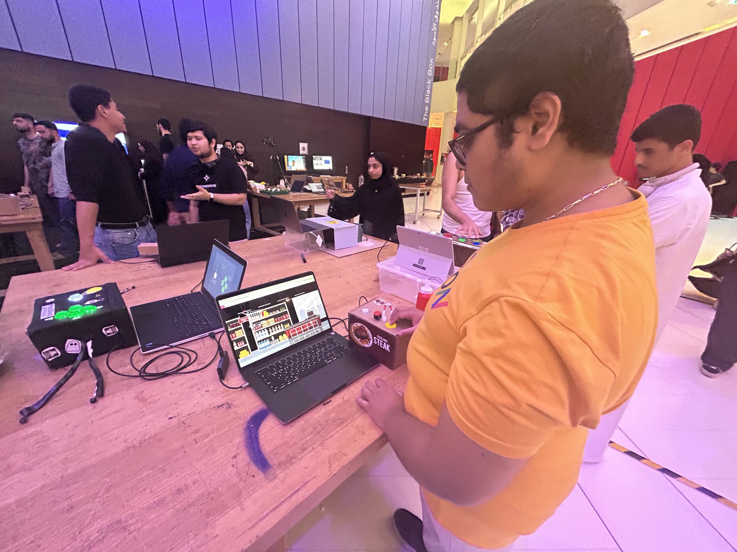
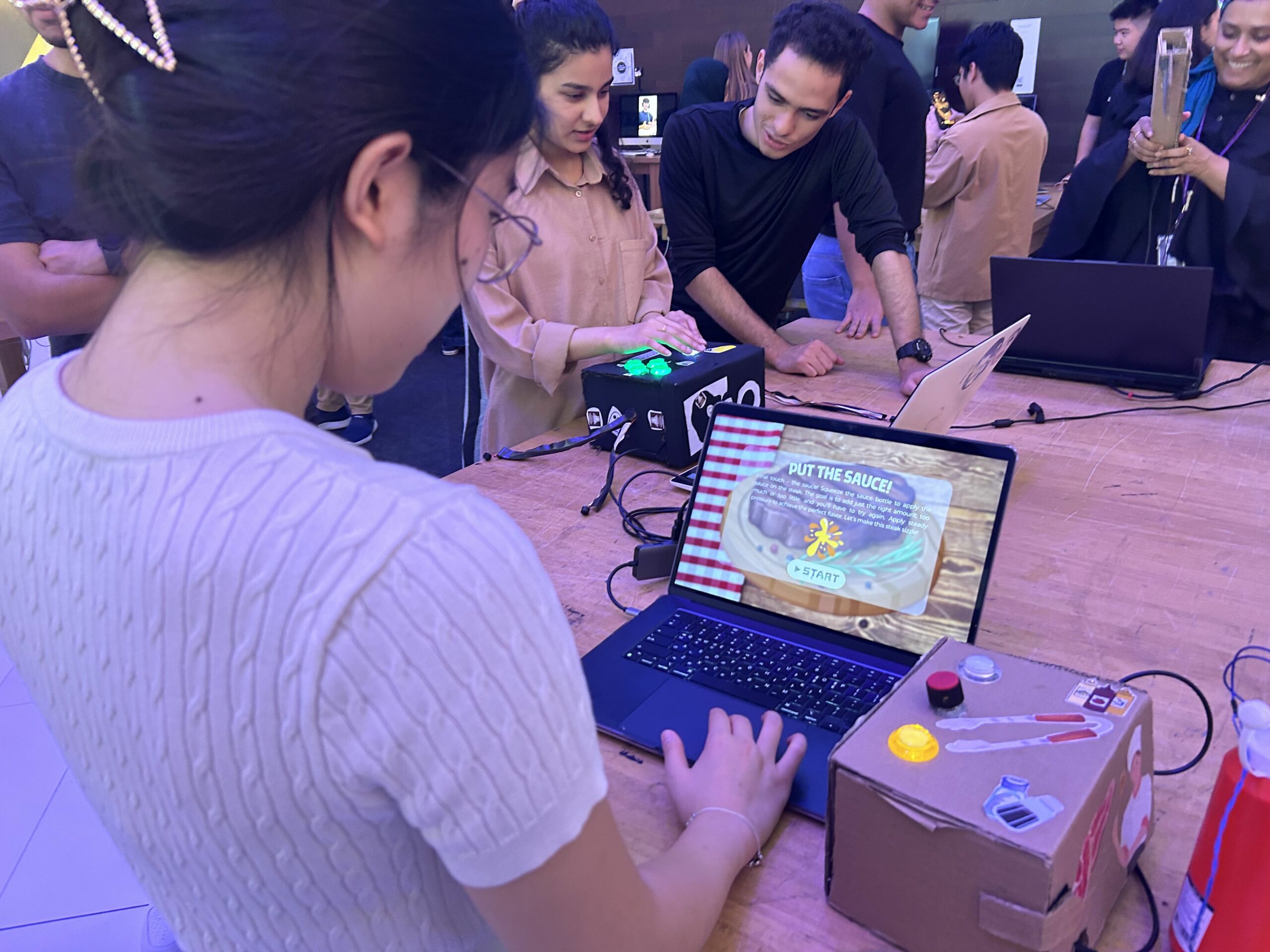
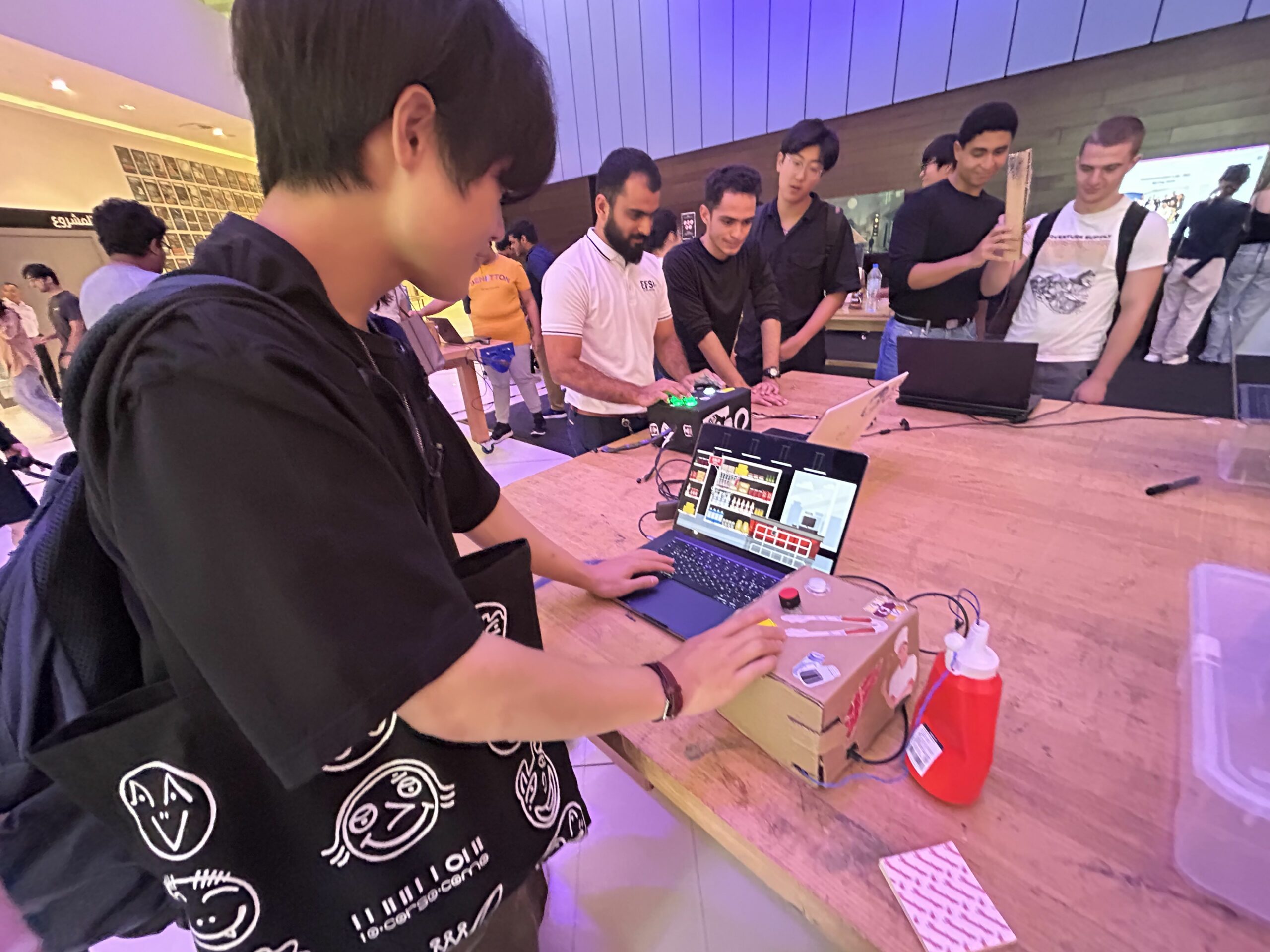
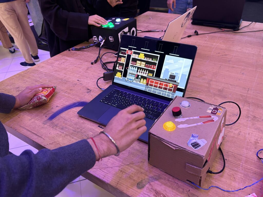
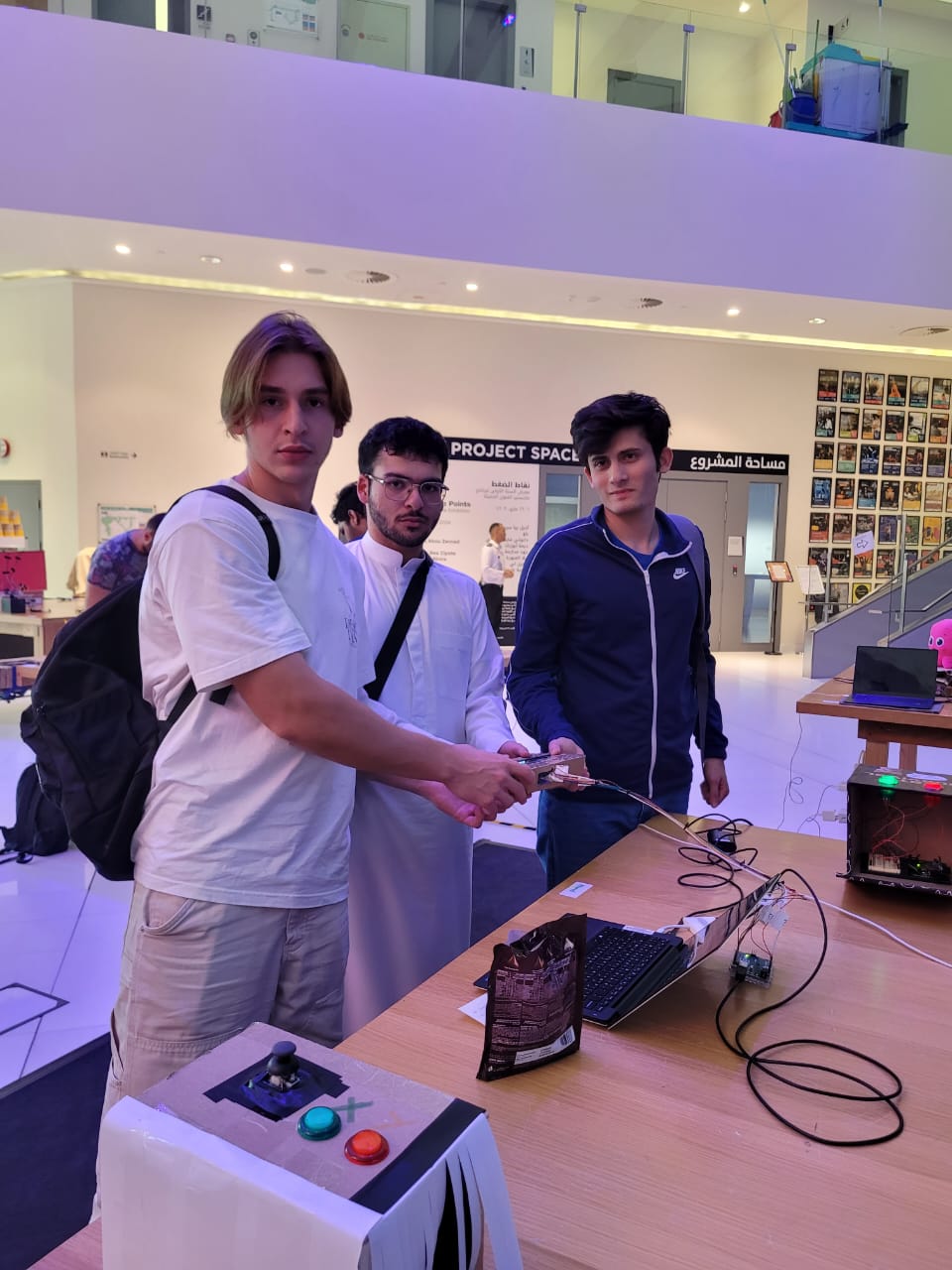
7. I.M. Showcase
After adding some future improvements (the day after this was posted) I showcased the project in the I.M. showcase. In general, everything went fine, although I had to adjust quickly the mapping of the values of the photoresistor as well as increase a bit of the volume of the piezo buzzers; although this was done, it was still hard to hear them. Nevertheless, the flashlight mechanic was more than enough to keep players engaged. Here is some footage:
And some photos:
Thanks for the class, I learned a lot!


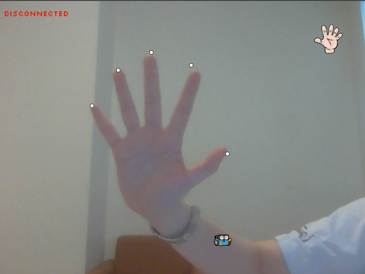
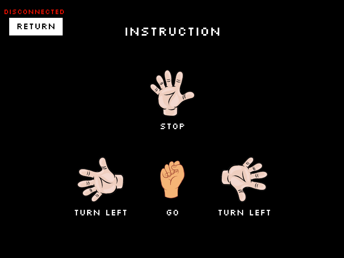

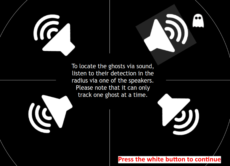
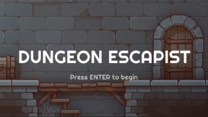
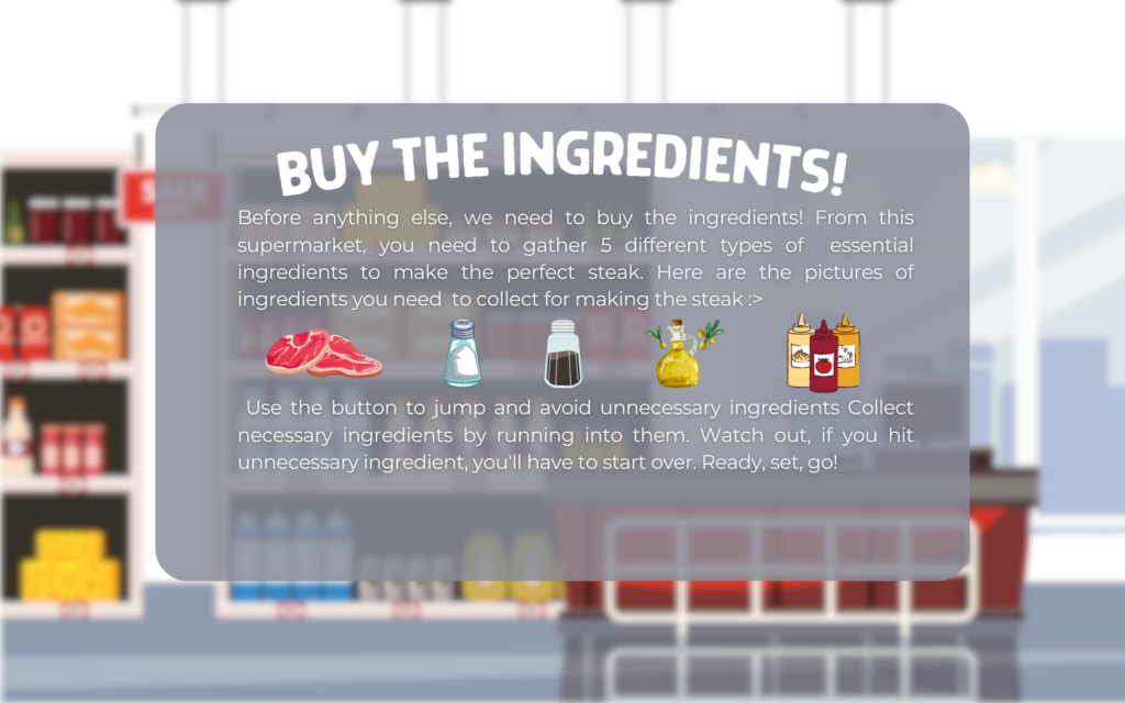 Stage 1 instructions
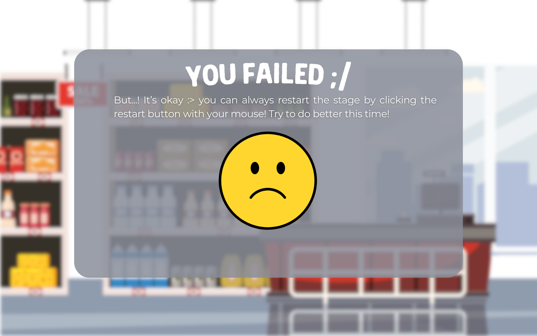


 game ending page
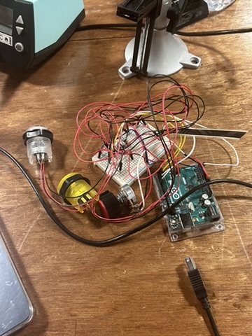
 Main Menu Screen
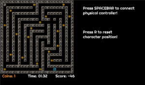
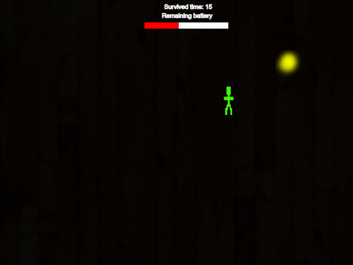
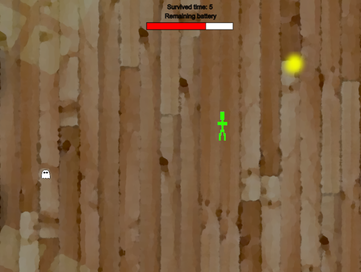
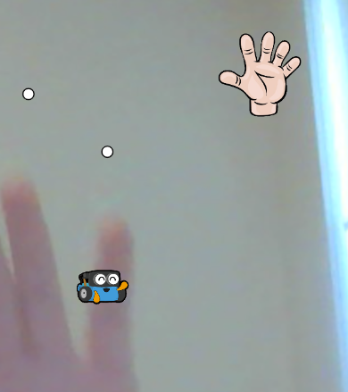
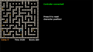 Game Screen with different maps
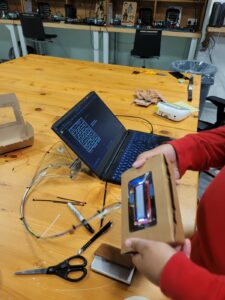 Initial User Testing.
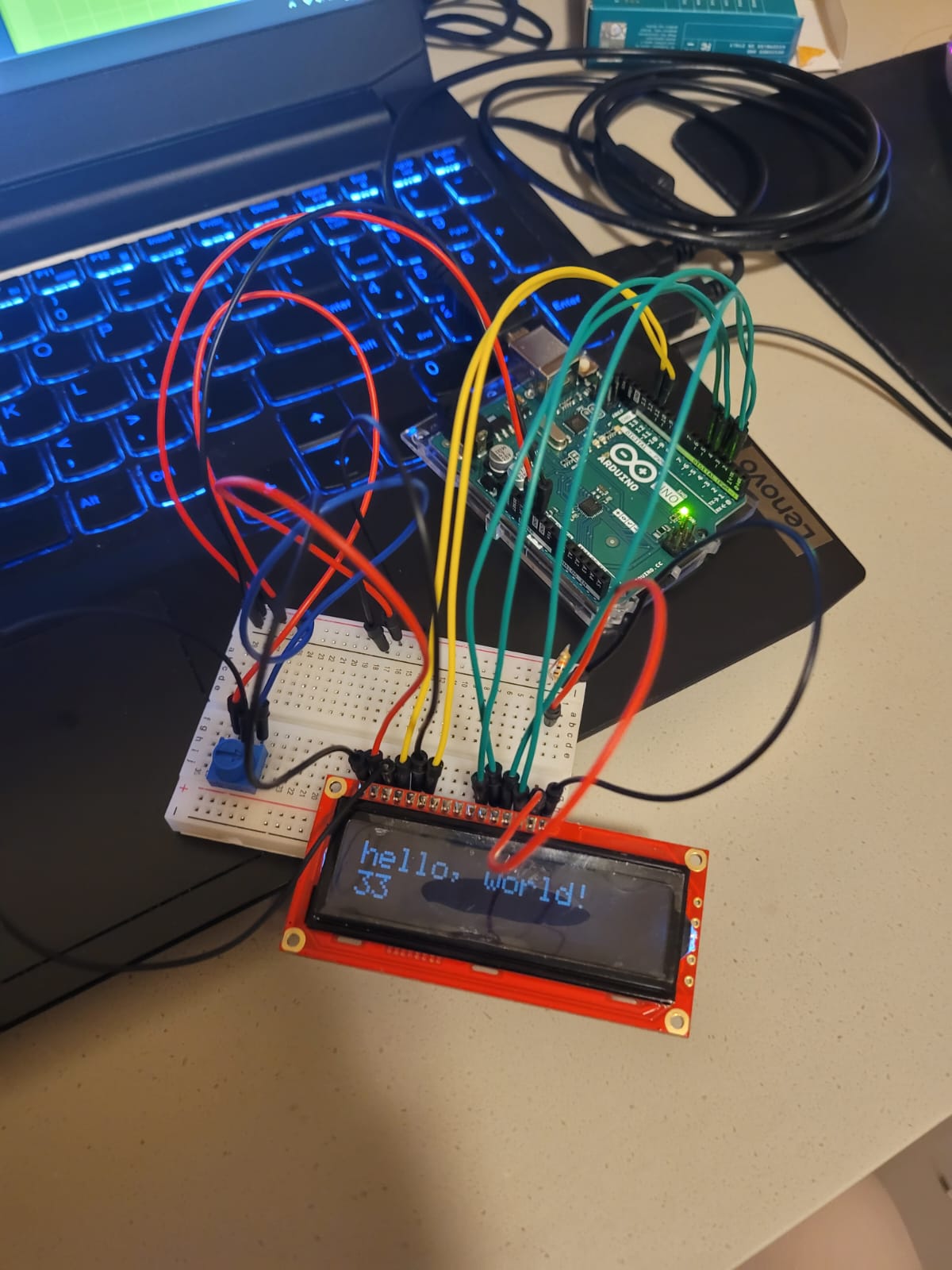
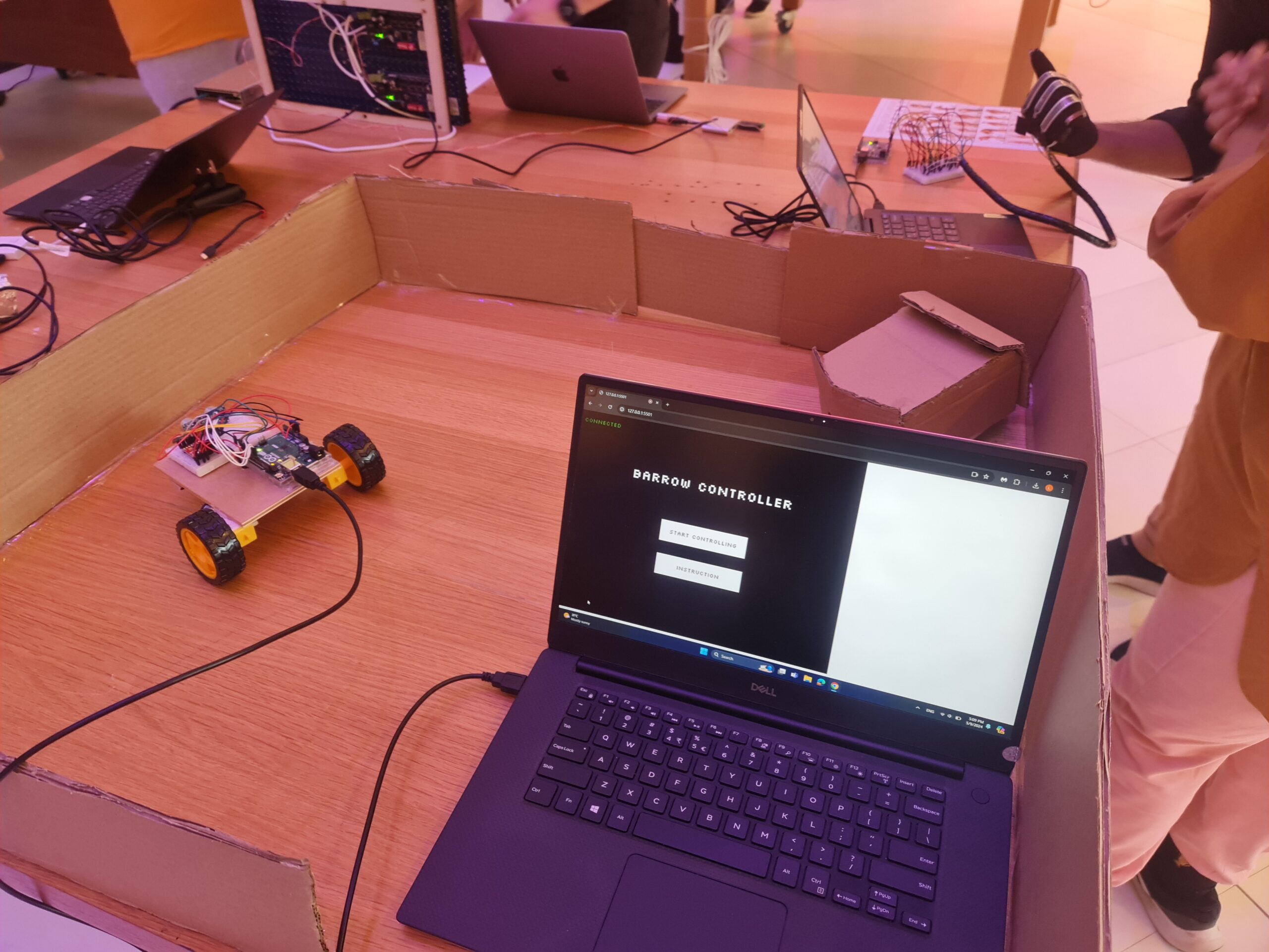
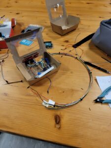 From prototypes to actual product
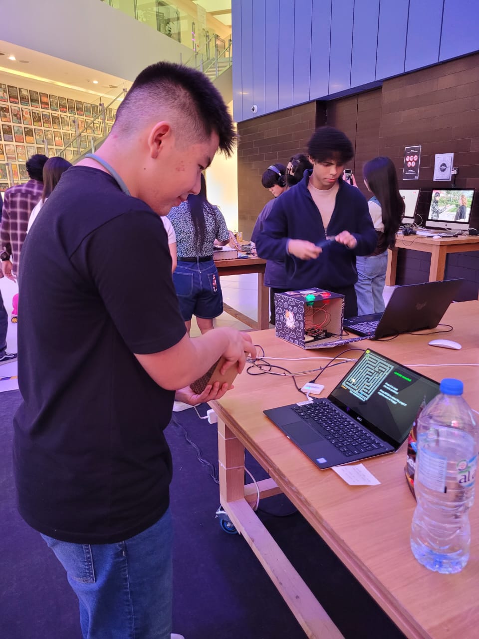