For this week’s exercise, I decided to make a switch that will detect breathing.
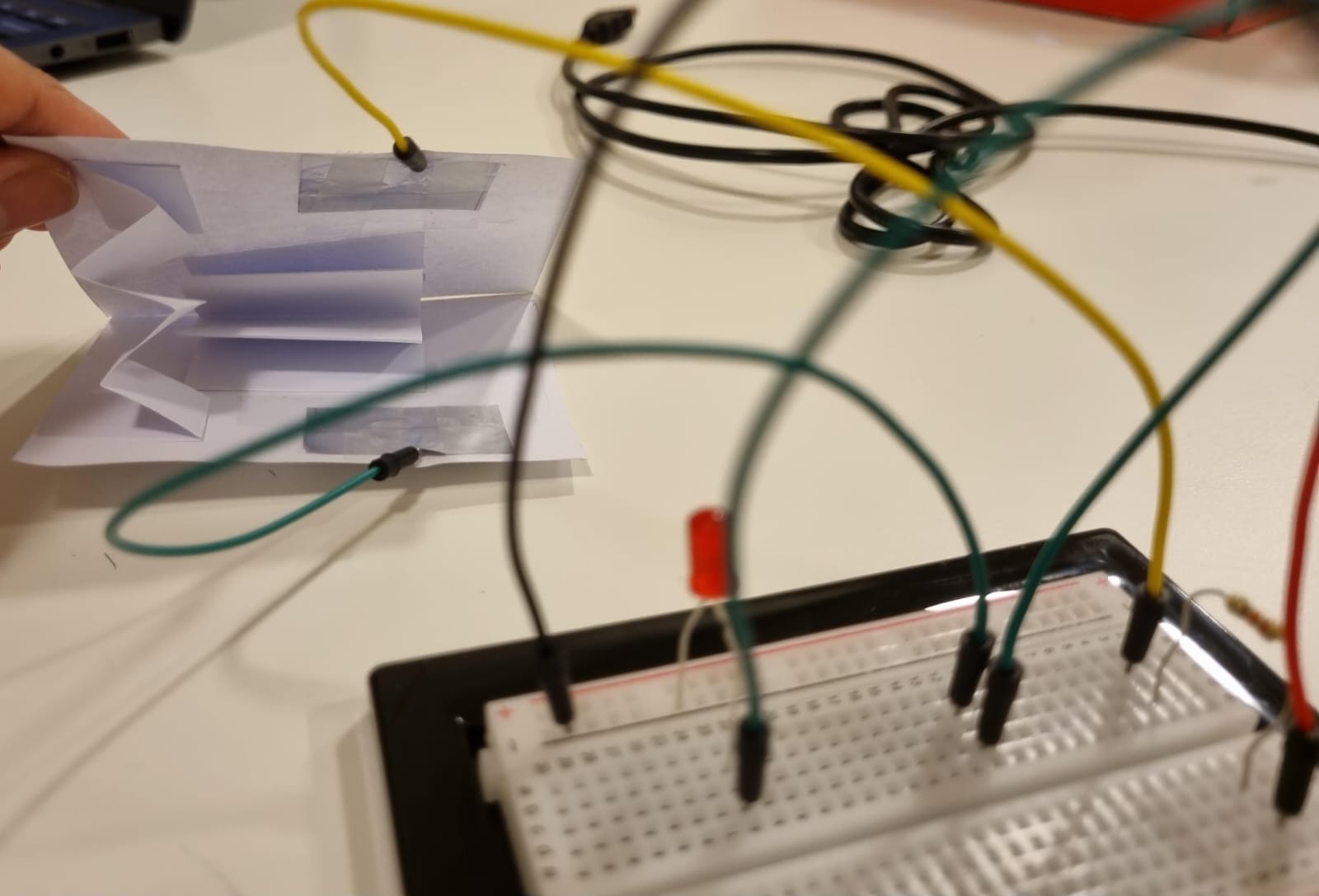
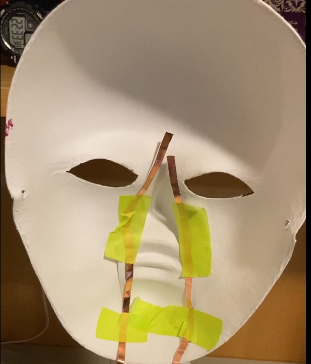
The rudimentary mechanism that functions as a switch is two pieces of tin foil which are separated by a small gap. When a person breathes in, their chest expands, and the pieces of foil are separated. They connect when a person exhales.
The materials needed for this project are:
- Breadboard
- Arduino board
- Tape
- Jumper wires
- Tin foil
- 330-ohm resistor
- 10K-ohm resistor
- 1 LED light
Wires with tinfoil are stung around a person’s chest to connect around the chest. There is no danger to the subject as the voltage of the circuit is really low and cannot pass through a body.
/
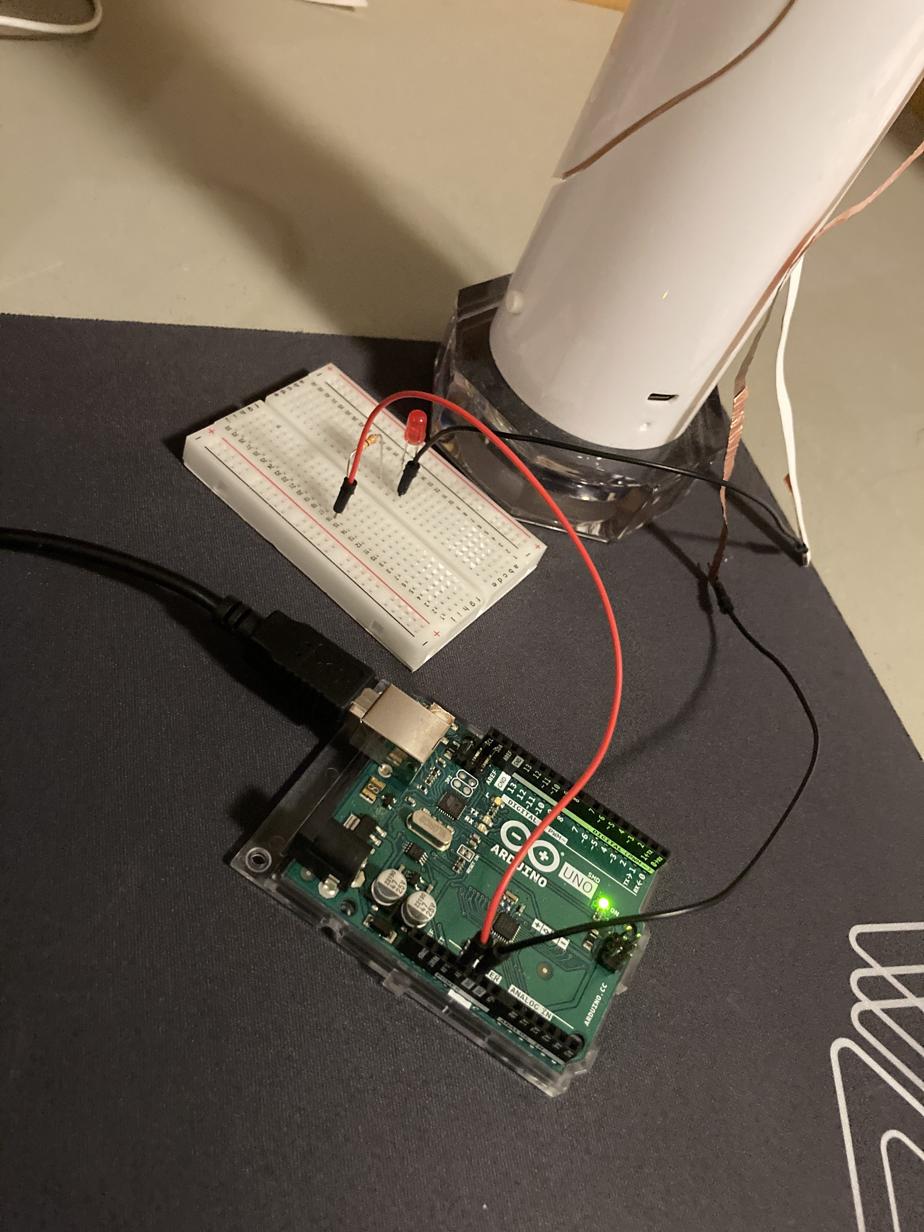
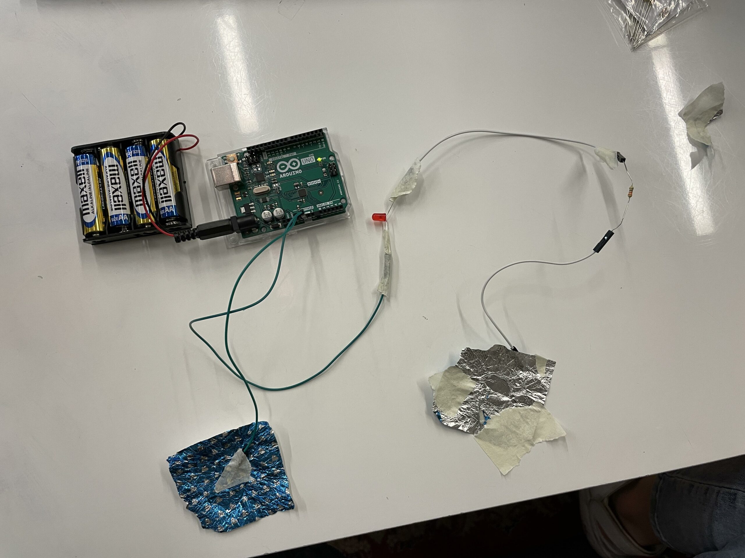
When the circuit is closed, the Arduino detects the closure and sends a signal to an LED to light up.
The switch/sensor
The circuit: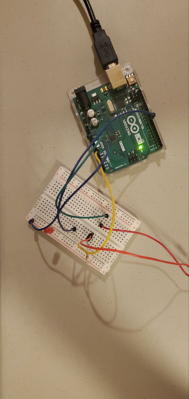
Similar devices already exist in the medical field, and as a part of a lie detector machine.
While creating this project, it was really fun to think of the many potential real world applications that machines such as this, basically simple switches, have.
I ran into some problems with the sensor when I made this. It was really hard to make the sensor align with itself, and the shirt to which it was attached was flimsy and moved around, causing the sensor to go off at times it should not have. Ideally, the entire contraption would be accompanied by an elastic band which would go around the chest of a person to keep the sensors secure and aligned, or the sensor would be attached directly to the skin, via tape.
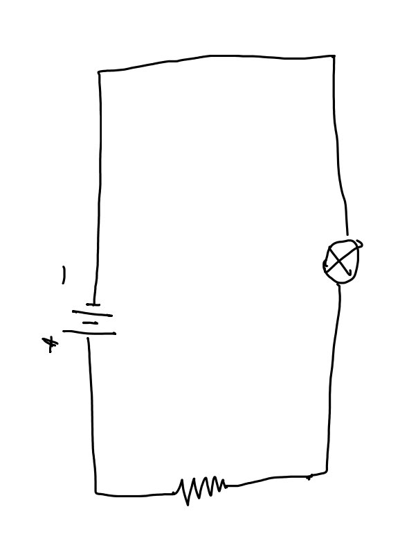
 Figure 1: Circuit Diagram
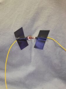
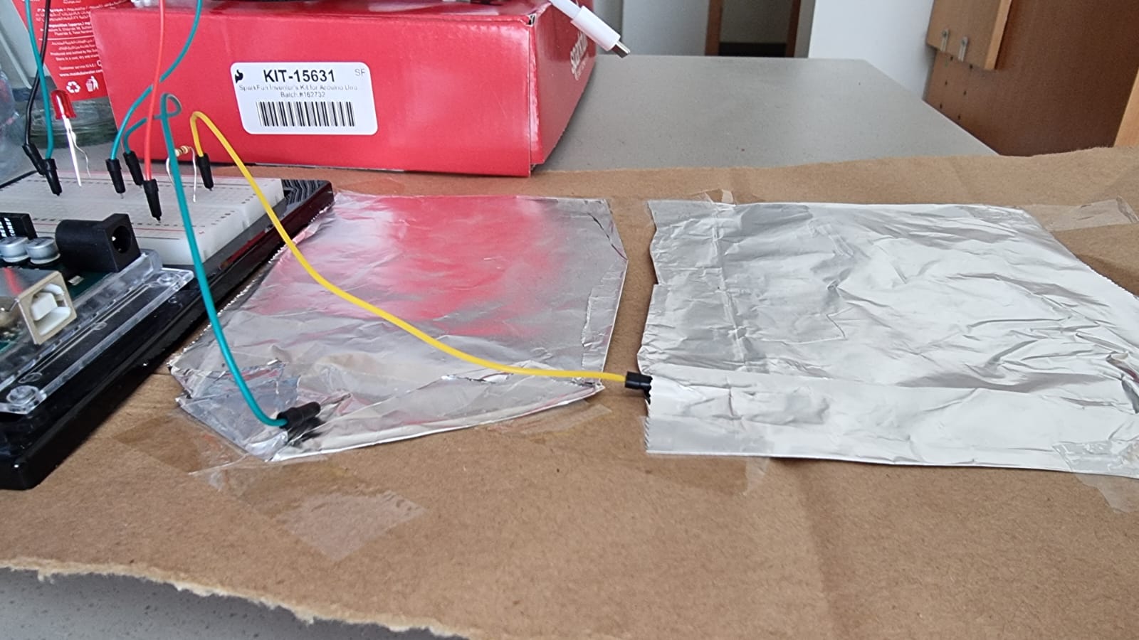 Figure 2: Switch terminals (the green terminal is +ve and the yellow terminal is -ve)