In the reading “Making Interactive Art: Set the Stage, Then Shut Up and Listen”, I understand that the creators are not the main performance. Interactive art allows users to impose actions onto the artworks instead of only observing. Therefore, their user experience and their understandings are different from each other with the same interactivity of the artwork.
Hence, we need to guide the users to the experience that we want them to have. As it is mentioned in the reading, we can give hints, use the space, use the design to allow the users to understand their respective actions. However, after that, it is the users’ performance. It will become their experience and their understandings because arts do not necessarily have a set meaning that we need the others to understand.
Finally, there are a variety of physical computing arts. Even though it may be in the same category, it does not mean that the users will have the same experience. For example, there are multiple projects about music. However, each project may require different skillset and understanding in music to interact with. Therefore, it is important to always experiment with the any project without the fear to be repetitive.
I wanted to explore how different components can interact with each other in a circuit. It is not simply how the buttons can control the lights or the variable resistors can transmit ranges of analog values. I want to understand if I can make an indirect interaction between the lights and the resistors such that I can light up another light using a light.
IMPLEMENTATION
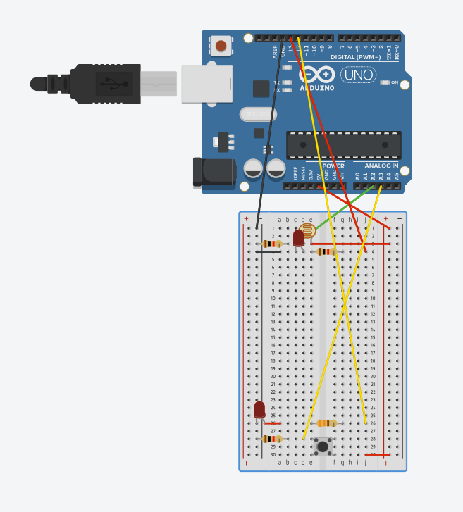
Using a button, I manipulate 1 light to light up as we push down on the button. For the analog input, I used the photocell to manipulate another light to light up when I am not covering it. However, another special thing is that the button can also control the second light when the photocell is covered.
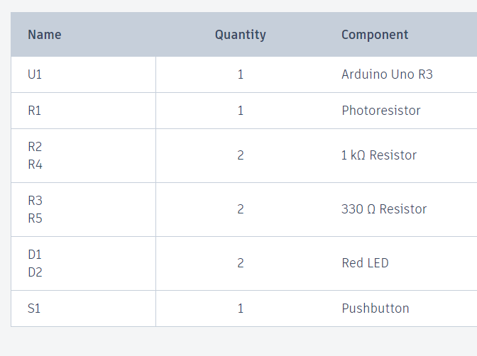
Below is an estimation of the material that I used:
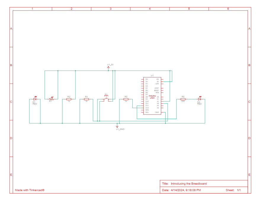
Below is the schematic for circuit:
Code implementation:
int led1 = 13;
int led2 = 12;
int brightness = 0;

// the setup routine runs once when you press reset:
void setup() {
  // initialize serial communication at 9600 bits per second:
  Serial.begin(9600);
  pinMode(led1, OUTPUT);
  pinMode(A3, INPUT);
  pinMode(led2, OUTPUT);
}

// the loop routine runs over and over again forever:
void loop() {
  // read the input on analog pin 0:
  int sensorValue = analogRead(A2);
  int buttonState = digitalRead(A3);

  sensorValue = constrain(sensorValue, 500, 900);
  brightness = map(sensorValue, 500, 860, 255, 0);

  analogWrite(led1, brightness);
  analogWrite(led2, brightness);

  Serial.println(sensorValue);
  delay(30);  // delay in between reads for stability


  if (buttonState == LOW){
    digitalWrite(led2, LOW);
  }
  else{
    digitalWrite(led2, HIGH);
  }
}
Video in Action
I realized that everything in my circuit is connected to each other even though there is no link between them. Take the inspiration of the movie “Everything, Everywhere, All at Once”, the ultimate result can only happen if all of the previous actions are done:
Challenges
It is quite difficult to grasp the concept of using different small circuits to serve for the bigger general circuit. I have a bit of trouble to utilize the brightness of another LED to adjust the value for the photocell. However, it works out in the end as I try to figure out the correct range of the new values of the photocell with the LED.
Reflection
Even though I was able to make a schematic diagram for the circuit, it is quite unorganized right now, I would like to learn more about how I can organize the wires and components so that it can be seen clearly in the diagram.
The articles “Physical Computing’s Greatest Hits (and Misses)” and “Making Interactive Art: Set the Stage, Then Shut Up and Listen” provide many insights and advice for artists and designers who want to create interactive physical computing projects and installations.
In “Physical Computing’s Greatest Hits (and Misses)”, the author reviews some of the most common themes and project ideas that take place in physical computing classes. What stood out to me is how he encourages students not to be discouraged if their ideas have been done before. As he points out, these themes are popular precisely because they offer room for originality and surprising variations. Even if the core interaction (e.g. theremin-like instruments, gloves, floor pads) has been explored, there are always opportunities to put new spins on it through the specific form, aesthetics, narrative, and context.
His different project types made me reflect on my own tendencies and biases when brainstorming IM concepts. I tend to gravitate toward certain projects which have the most creative and interesting aspects in sight. I don’t want to just satisfy assignment requirements but have the project with a certain goal in mind to have a certain effect on the user.
“Making Interactive Art: Set the Stage, Then Shut Up and Listen” article offers advice that somehow conflicts with my instincts as a designer. Author advises interactive artists to avoid pre-scripting the participant’s experience and interpretations. Let the audience discover meaning for themselves through open-ended interaction with the work.
This is quite different from other design contexts like UX, where the goal is often to carefully guide the user through a curated experience towards a specific goal. But with interactive art, you get more authentic audience engagement and emotional resonance by leaving room for ambiguity, surprise, and personal interpretation. It requires the artist to give up some control, which can feel uncomfortable. But the end result is a richer dialog between the artist and the audience. For example, when I was designing my midterm project, I left players with a choice (e.g. pick up the ring or not) so players could act accordingly. For communications lab projects, we also try to design concepts that actively consider user input (e.g. alternating storyline and so on). I still feel like there is some level of prediction that needs to happen, nothing is truly open world experience as we don’t have enough resources or computing power for that, but we can try to get as close as possible.
Author’s advice to “shut up and listen” – pay close attention to how people interact with and react to the work – also struck me as highly relevant to interaction design in general, not just artistic contexts. We can learn so much by observing where our creations fail to improve in the future. Therefore, staying open to that feedback is essential for refining the work. This is something I did for my midterm as well by asking my friends to play game and provide constructive criticism.
In conclusion, these two articles provide many thought-provoking ideas to anyone trying to overcome the challenges of creating meaningful interactive experiences. While some of the advice may be particular to media art contexts, much of it feels widely applicable to interaction design as a whole. These are things I already take into account in my assignment, and now I feel even more aware moving further into complex projects.
For this assignment I really wanted to use Ultrasonic sensor and experiment with its detecting capabilities, hence the name of the project – multi-detector. I wanted to have three separate distances: near, medium, far to have different activations. (For example, different lights or sounds). To satisfy projects requirement (analog input/output + digital input/output) I decided to implement other elements since ultrasonic can be considered as both. This enabled me to expand project and make it more interactive. I decided to add RGB LED as an analog output source which in itself is based on ultrasonic sensor readings. A digital output LED in this case would be the status LED which is activated by digital input slider switch. Conversely, the status is also indicated by short lasting sound by second piezo speaker. The analog input is my potentiometer which controls the pitch of the buzzer. As you can see we have more than one digital/analog inputs and outputs and making sure they all work well together in a sensible manner was the main goal of this project.
Process:
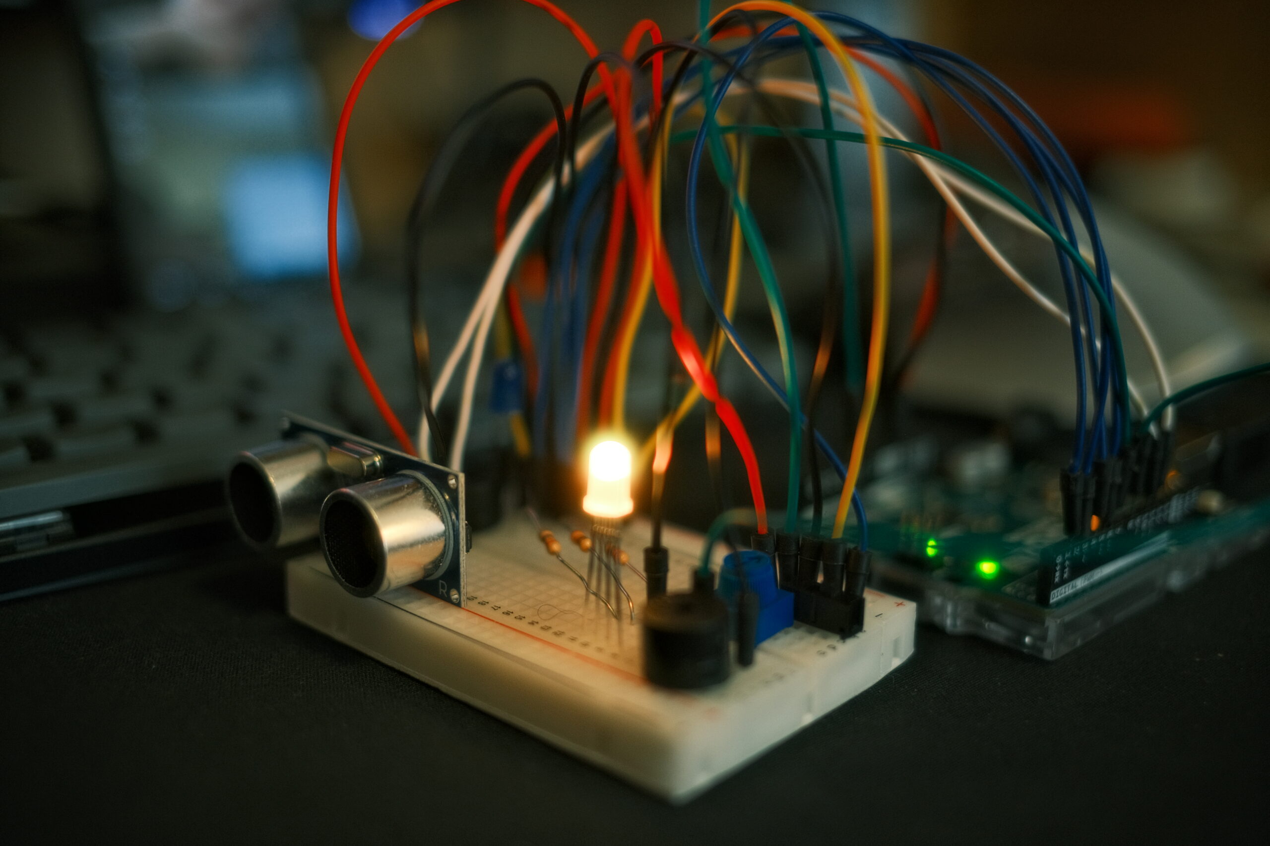
The design is quite intuitive. User can turn on the sensor which is indicated by blue led briefly lit up and brief sound played by second piezo speaker. Then user can point the ultrasonic sensor at different objects. RGB LED will light up in different colors based on the distance to that object. For far distances I am using green light, for medium – yellow and for close red. I decided to use RED for close along with buzzing sound to demonstrate a state of emergency, something that is often used in real life applications. Providing both striking visual stimulus (RED color) and audio (high pitch sound) signals the user of proximity in urgent manner. This might be useful for larger scale projects where detection of a foreign object has to be alerted to user at all costs.
I used Tinkercad for simulating my project online and as seen on the video below, it works perfectly fine: (I tried to rearrange objects for best visibility possible).
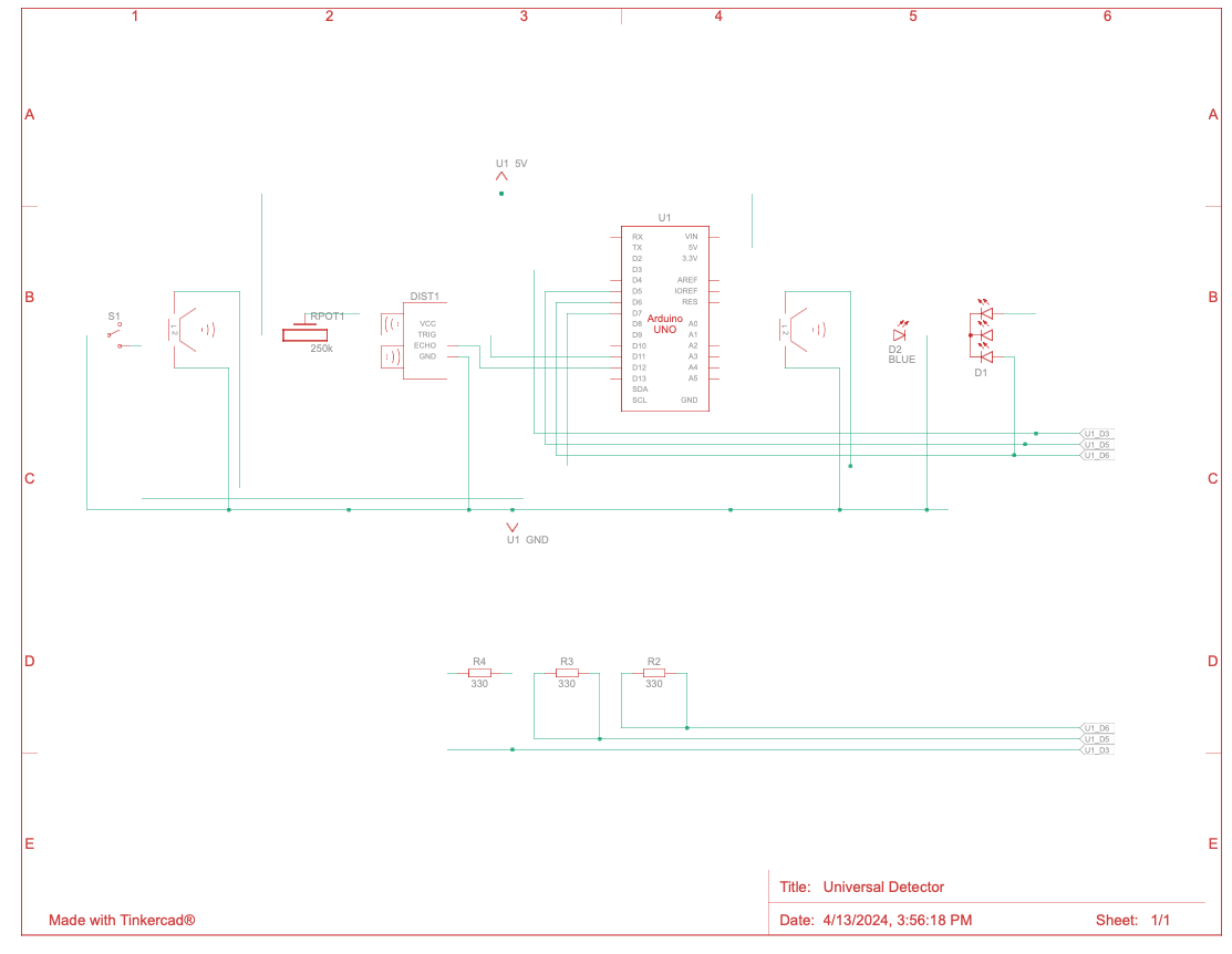
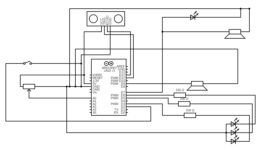
I am also including a diagram form Tinkercad conversion which did not look fully proper with incomplete connections and questionable alignments, hence I used Circuit Diagram Web Editor to draw design myself from scratch (ultrasonic is in center since it has both inputs and outputs). For the future assignment I will only use whichever is most appropriates based on your feedback.
Code:
// pin connections
const int trigPin = 11;               // Pin connected to the trigger pin on the ultrasonic sensor
const int echoPin = 12;               // Pin connected to the echo pin on the ultrasonic sensor
const int redPin = 3;                 // Pin to control the red LED inside the RGB LED
const int greenPin = 5;               // Pin to control the green LED inside the RGB LED
const int bluePin = 6;                // Pin to control the blue LED inside the RGB LED
const int piezoPin = 9;               // Pin for the first piezo speaker (used for siren)
const int potPin = A0;                // Analog pin connected to the potentiometer
const int switchPin = 2;              // Digital input pin for the switch
const int secondPiezoPin = 7;         // Pin for the second piezo speaker (used for feedback on switch toggle)

float distance = 0;                   // to store the measured distance
bool lastSwitchState = HIGH;          // to track the last state of the switch

void setup() {
  Serial.begin(9600);

  // Set pin modes
  pinMode(trigPin, OUTPUT);
  pinMode(echoPin, INPUT);
  pinMode(redPin, OUTPUT);
  pinMode(greenPin, OUTPUT);
  pinMode(bluePin, OUTPUT);
  pinMode(piezoPin, OUTPUT);
  pinMode(secondPiezoPin, OUTPUT);
  pinMode(potPin, INPUT);
  pinMode(switchPin, INPUT_PULLUP);   // internal pull-up resistor for the switch
}

void loop() {
  bool currentSwitchState = digitalRead(switchPin); // read the current state of the switch

  // check if the switch state has changed
  if (currentSwitchState != lastSwitchState) {
    if (currentSwitchState == LOW) {
      // plauy a brief sound on the second piezo speaker when the switch is toggled
      tone(secondPiezoPin, 1000, 200); //  a 1000 Hz tone for 200 milliseconds
    }
    lastSwitchState = currentSwitchState; // Update the last known state of the switch
  }

  // actions when the switch is active
  if (currentSwitchState == LOW) {
    distance = getDistance(); //  distance - ultrasonic sensor

    Serial.print(distance);
    Serial.println(" in");

    //  RGB LED control
    if (distance <= 10) {
      analogWrite(redPin, 255);       // Close distance - turn RGB LED red
      analogWrite(greenPin, 0);
      analogWrite(bluePin, 0);
      playSiren();                    // siren on
    } else if (distance > 10 && distance < 20) {
      analogWrite(redPin, 255);       // Medium distance - turn RGB LED yellow
      analogWrite(greenPin, 50);
      analogWrite(bluePin, 0);
      noTone(piezoPin);               // Stop siren
    } else {
      analogWrite(redPin, 0);         // Far distance - turn RGB LED green
      analogWrite(greenPin, 255);
      analogWrite(bluePin, 0);
      noTone(piezoPin);               // Stop siren
    }
  } else {
    // Turn off all outputs when the switch is not active
    analogWrite(redPin, 0);
    analogWrite(greenPin, 0);
    analogWrite(bluePin, 0);
    noTone(piezoPin);
  }

  delay(50);  // Short delay to stabilize readings
}

// Function to measure distance using ultrasonic sensor
float getDistance() {
  digitalWrite(trigPin, HIGH);
  delayMicroseconds(10);
  digitalWrite(trigPin, LOW);

  float echoTime = pulseIn(echoPin, HIGH);
  return echoTime / 148.0;  // Convert time to distance
}

// control siren based on distance
void playSiren() {
    int potValue = analogRead(potPin);  // read the potentiometer value
    int volume = map(potValue, 0, 1023, 0, 255);  // Map it to PWM range
    analogWrite(piezoPin, volume);  // control volume


}
In the setup() function, each component is initialized to its respective pin mode, ranging from outputs for LEDs and piezo speakers to inputs for the ultrasonic sensor and potentiometer. The main loop() continuously checks the state of a digital switch to control the overall system operation, toggling functionality and triggering a brief alert sound from a secondary piezo speaker upon state changes. Distance is measured using an ultrasonic sensor, with the results dictating the color output of an RGB LED and the activation of a siren on the primary piezo speaker, whose volume is adjusted by a potentiometer. Everything else I already discussed in introduction and commented in the code. As you can see it is quite extensive so hopefully it should answer all your questions.
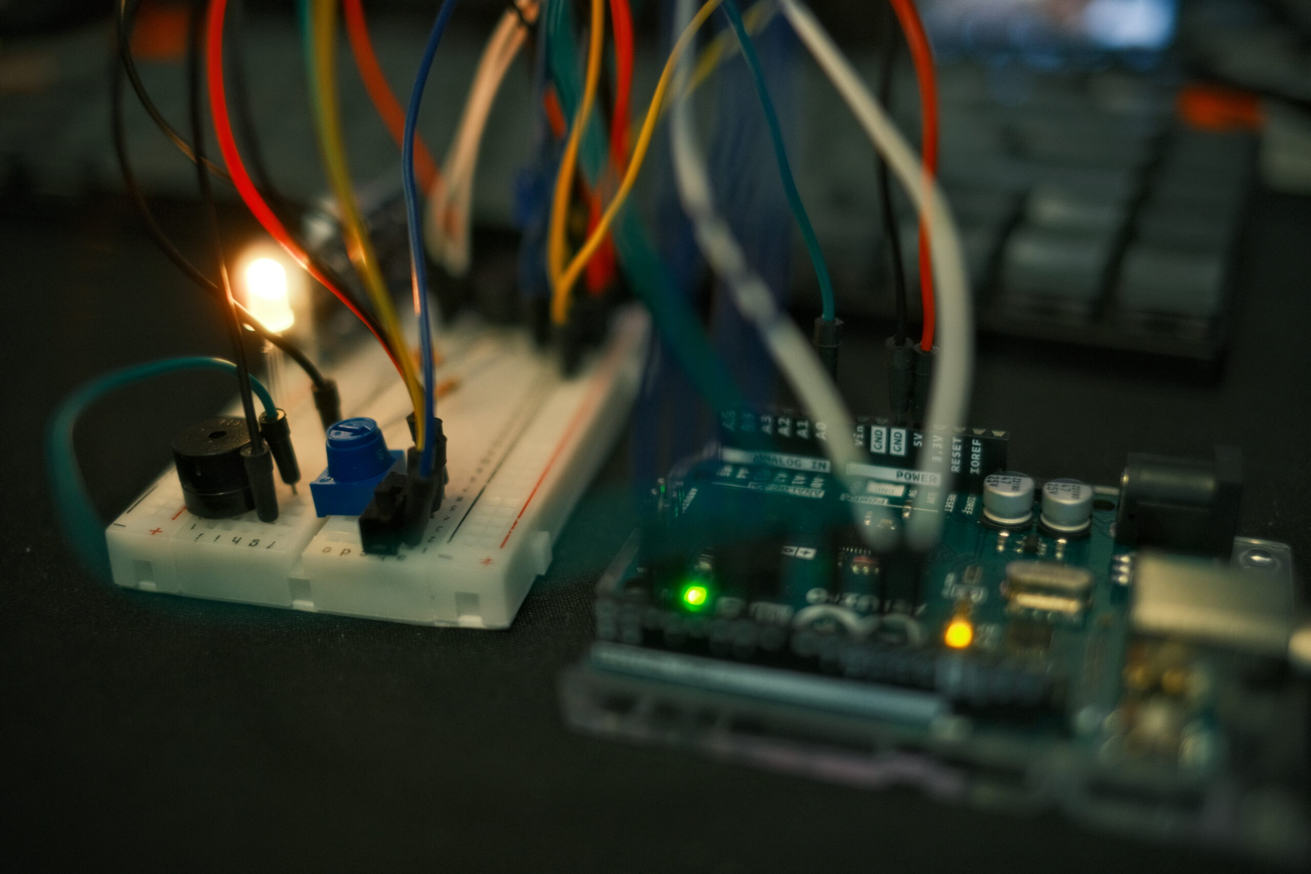
Demonstration:
Challenges:
While integrating the various components in this project, I faced some interesting challenges. Managing the piezo speaker’s volume with analogWrite() proved to be tricky because the function doesn’t directly control voltage output but instead modulates the PWM signal, which isn’t ideal for driving piezo speakers. I followed a tutorial for setting up an ultrasonic sensor from Sparkfun itself so that was fairly straightforward. I tried my best to manage the colors of the cables properly but eventually, I ran out of black wires so I used yellow as a substitute. Redrawing schematic was not as much challenging as it was time consuming. In the future, I would like to find a faster way to do this while satisfying project requirements.
Reflection:
All in all, I am quite happy with how my project turned out. I think what I learned through this project might be very useful for my future assignments and final project since I learned more about digital/analog inputs outputs as presented in Arduino, as well as reading/creating schematics and testing out project both in simulation and in real world. This project could easily be expanded by incorporating more components and making it part of something bigger since its sole responsibility for now is just detection.
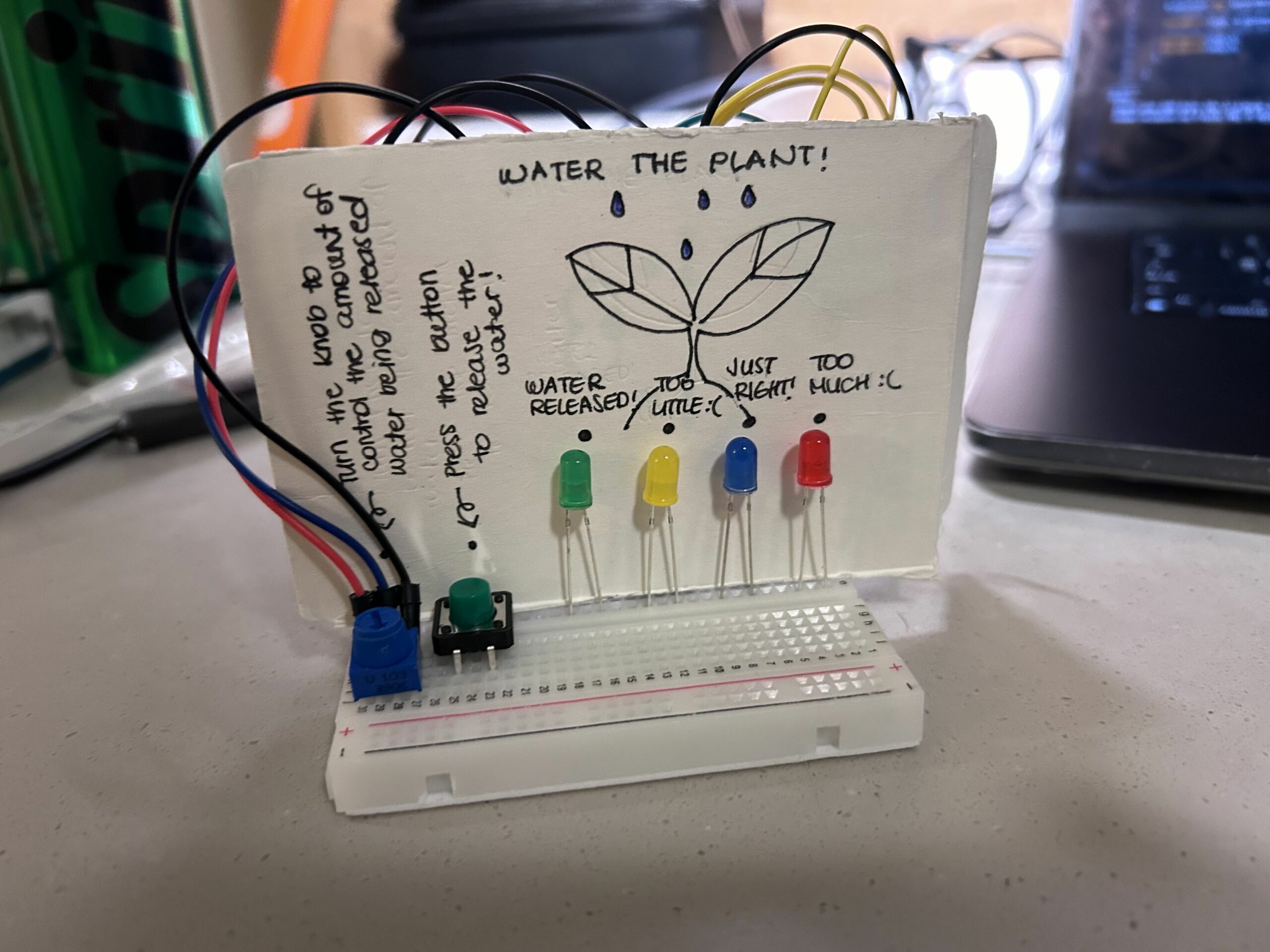
As soon as I saw the instructions for this assignment, I knew that I would like to use the potentiometer creatively. The potentiometer reminded me of the water faucet in my grandmother’s backyard which controls the amount of water being released. Then, randomly, I got reminded that my grandmother loves plants. So, I wanted to do something related to plants for the concept. Then, I decided to do something that is related to “watering the plant”. There is always an adequate amount of water to give the plant. If we give too much water, the plant will die. If we give too little water, the plant will also die. So, I decided to make my project for this assignment with the concept of an “indicator” that shows the plant’s feeling towards the amount of water given (too little, just right, too much) through LED lights based on the water given to it (value of potentiometer).
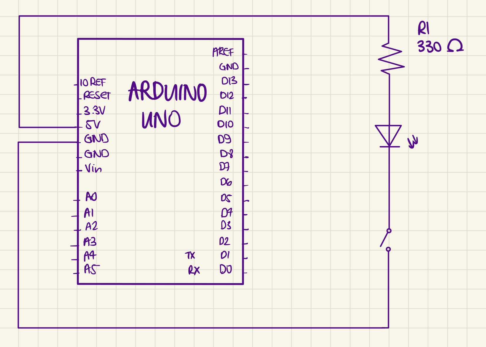
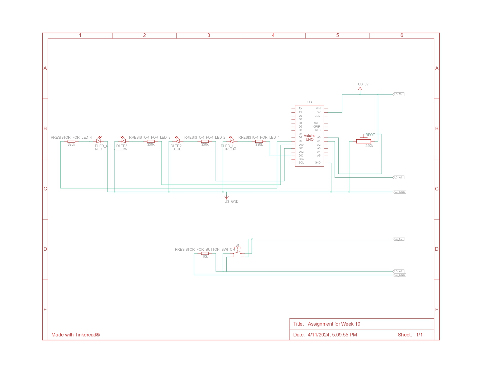
Arduino Diagram (Schematic):
As you can see from the schematic diagram above, there are three LED lights associated with the potentiometer and 1 LED light associated with the button switch. The green LED light (led1), which is associated with the button switch is attached to pin 13. Then the red (led4), yellow(led2), and blue(led 3) LED lights, which are associated with the potentiometer, are connected to pins 9,10, and 11 respectively. The red jumper wires are used to indicate 5V connections and the black jumper wires are used to indicate the GND connections. Power from the 5V pin is distributed to both the digital sensor (the switch) and the analog sensor (the potentiometer). Data from the switch is sent to the A1 pin, while data from the potentiometer is sent to the A0 pin. Then, all circuits complete their path back to the GND pin.
Arduino Code:
// variables
//declaring and initializing brightness to 0
int brightness=0;

//the pin the LEDs are attached to:
//related to the switch
int led1=13; //green light
//related to the potentiometer
int led2=11; //yellow light
int led3=10; //blue light
int led4=9; //red light


void setup() {
//declaring input and output
  pinMode(A1,INPUT);
  pinMode(led1, OUTPUT);
  pinMode (led2,OUTPUT);
  pinMode(led3, OUTPUT);
  pinMode(led4, OUTPUT);

}

void loop() {
  int sensorValue= analogRead(A0);
  int buttonState= digitalRead(A1);
  // turning on and off led1 using the switch:

  //led 1 is turned on when the button is pressed;
  if (buttonState== HIGH){
    digitalWrite(led1, HIGH);
  } else{
    digitalWrite(led1, LOW);
    //making sure other LED lights are switched off
    analogWrite(led2, 0);
    analogWrite(led3, 0);
    analogWrite(led4, 0);
  }
//related to the potentiometer
  if ((sensorValue < 341)&&(buttonState==HIGH)){
   //mapping the brightness for the fade effect (bright>> dim)
    brightness= map (sensorValue,341,0, 0, 255);
    //turning on the led2 when the potentiometer's value is lower than 341
    analogWrite(led2, brightness);
    //ensuring other lights are not turned on
    analogWrite(led3,0);
    analogWrite(led4,0);
  }
  else if ((sensorValue <682)&&(buttonState==HIGH)){
    //mapping the brightness for the fade effect (dim>> bright)
    brightness= map (sensorValue,341,682, 0, 255);
    //turning on the led3 when the potentiometer's value is in between 341 and 682
    analogWrite(led3, brightness);
    //ensuring other lights are not turned on
    analogWrite(led2,0);
    analogWrite(led4,0);
  }
  else if ((682 <sensorValue)&&(buttonState==HIGH)){
    //mapping the brightness for the fade effect (dim>> bright)
    brightness= map (sensorValue,682,1023, 0, 255);
     //turning on the led4 when the potentiometer's value is greater than 681
    analogWrite(led4, brightness);
    //ensuring other lights are not turned on
    analogWrite(led2,0);
    analogWrite(led3,0);
  }

}
As shown above, I initially declared and initialized the brightness to 0, and set up variables for the LED lights attached to their respective pins. I then designated these as outputs and input in the setup() function. In the loop() function, I declared sensorValue and buttonState to adjust the LED lights based on input from the potentiometer and the switch. Utilizing if-else statements, I controlled the LED lights based on this input. For example, led1 turns on only if the button is pressed, indicating that the user wants to start ‘releasing’ water. For the other LEDs, I divided the potentiometer’s range of 1023 into three, setting specific ranges for each light: if the value is less than 341, the yellow LED (LED 2) lights up; if the value is between 341 and 682, the blue LED (LED 3) activates; and if it’s above 682, the red LED (LED 4) turns on.
A notable aspect of this if-else statement is the use of the map() function to create a fade effect from dim to bright or vice versa. As the potentiometer’s value increases within LED 2’s range, the light dims, indicating that the ‘water level’ is moving away from ‘too little.’ In contrast, LEDs 3 and 4 brighten as their ranges are reached, signaling an increase in water level.
Another key point is that every lighting condition includes buttonState==HIGH. I included this to ensure that the LEDs only activate when the button is pressed, signifying that water is being dispensed.
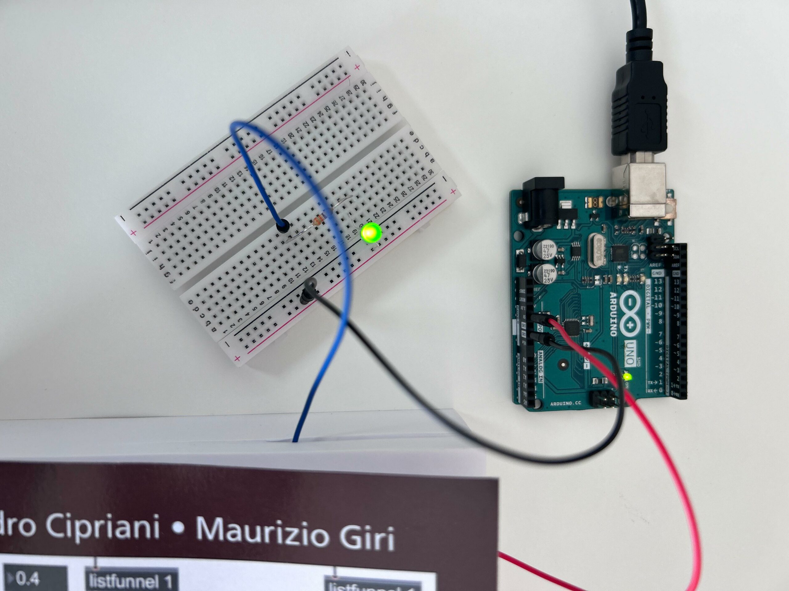
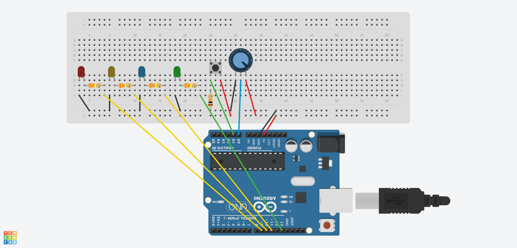
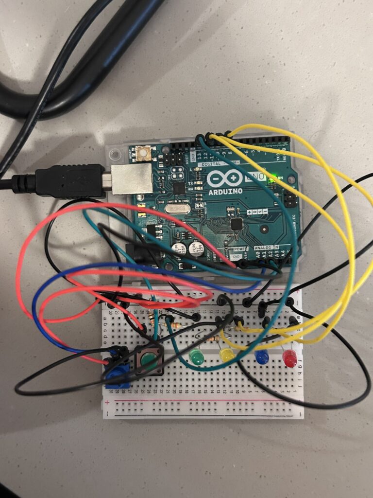
Built circuit based on the schematic diagram
circuit built
final product with illustrations
Demonstration of the Final Outcome:
It was a little hard for me to control the potentiometer as I had taken this video by myself. However, you could see the lights getting dimmer or brighter as I control the potentiometer!
Challenges and Reflection:
Overall, as always, I enjoyed doing this assignment. I am a person who is new to Arduino and circuits. So, it was quite challenging for me to fully understand the concept of circuits and the logic behind them. However, I think this project helped me a lot in understanding and getting familiar with Arduino and circuits. During our last class, the professor recommended drawing the schematic diagram first before building the circuit with our hands. So, I tried to do so. And I found this helpful in figuring out how to build the circuit that I want to incorporate into this project. I think I would draw schematic diagrams first every time before starting to build the circuits with my hand. I am genuinely satisfied with my project. I found my project quite cute and interesting. However, I think it could be improved by adding some features such as randomizing the “just right” value of the plant so that the user could play a simple guessing game with this.
Making Interactive Art: Set the Stage, Then Shut Up and Listen
I agree with the author that artists should not ‘pre-script’ what will happen and offer interpretations in the notes beside their interactive artwork. I believe that the beauty of interactive artwork lies in the freedom for the audience to contemplate, suggest the artists’ intentions beyond the project, and formulate their own interpretations of the artwork. Honestly, I think that the interactive artwork is not truly ‘interactive’ anymore if the audience must follow and do whatever is pre-scripted by the artist, as it is no longer a ‘conversation’ with the project. As how the author of today’s reading and Crawford in our previous reading (‘The Art of Interactive Design’) mention, interactivity is like a two-way conversation in which two actors alternately listen, think, and speak. I believe that if the audience has to follow what the artists have pre-scripted, then the ‘think’ process of interactivity is gone, and it would no longer be interactive. As the author of today’s reading suggests, it is fine to lead the audience to do certain things using the interactive artwork by making some aspects not approachable and giving hints through the artwork itself; however, we should not remove the freedom of the audience to take the form of actions they want to interact through the interactive artwork. Also, upon reading the article, I thought that well-made interactive artwork is like a well-made movie. A well-made movie makes the audience eager to share their feelings after watching it and the intentions of the director they perceived. This sharing of different perspectives on one movie is what lots of movie lovers love to do after watching the movie. I believe that well-made interactive artwork also enables such joy of sharing. And this is the beauty of interactive artwork as well.
Physical Computing’s Greatest Hits (and misses)
Among the reviews of the project themes that the author frequently sees, I found ‘Things You Yell At’ very familiar. The project with this theme involves reacting to a yell. This reminded me of ‘Space Navigator,’ my midterm project for Introduction to Interactive Media. My midterm project involved a voice mode, which enabled the player to control his or her rocket using his or her voice volume. I agree with the author that the interaction in this kind of project is very simple but very satisfying. My project just involved moving the rocket up and down with the voice volume, which is quite straightforward, but that was the main point of my game. Many who played my midterm project found the voice mode fun and satisfying as it allowed them to ‘yell’. I think that the act of yelling as a method of interaction gives people pleasure because it is intuitive, physically engaging, and offers an immediate effect on the game. Also, from my midterm project and part of today’s reading talking about this project theme, I realized that complexity in the project or game does not always equate to deeper or more satisfying player engagement. Sometimes, it’s the straightforwardness, such as yelling to control a game, that enables an enjoyable and satisfying experience for the audience.
Among the physical computing projects, Fields of Grass piqued my interest the most. Thinking about it, I believe that the sensors could be arranged in various ways so that the output changes based on not only the position of the hand, but also the pressure applied. Imagine creating a virtual landscape where the terrain shifts depending on how firmly you press your hand! Delicate touches could reveal hidden paths or trigger calming sounds, while heavier presses might activate bolder visuals or more dramatic effects. This additional layer of interaction would add a whole new dimension to the experience. Beyond pressure, the sensor arrangement could be tweaked to respond to other hand interactions. For instance waving your hand across the field to control the movement of virtual birds, or gently cupping your hand to scoop up shimmering virtual butterflies. Moreover, Fields of Grass could be adapted to respond to footsteps, creating a truly immersive experience where walking through the installation ripples the virtual landscape. In a museum setting, the project could be transformed into an educational tool. Visitors could “grow” different virtual plants by placing their hands in designated areas and manipulating pressure or movement to influence factors like sunlight or water. The applications could even reach the field of physical therapy, with the virtual world responding to specific hand motions or muscle control, providing a visually engaging way to track progress.
Making Interactive Art: Set the Stage, Then Shut Up and Listen
Integrating this reading’s notion into the Fields of Grass projects, the users will be free to interact with the grass, but the output will be in the prescribed yet non-deterministic way. If we assume each user’s interaction to be a performance, we can also assume collaborative performances between 2 users generating new form of performance between multiple users and the project. Their combined hand movements and pressure could trigger entirely new visual and audio responses, fostering a collaborative performance unlike anything seen before. The project becomes a bridge, translating individual actions into a shared, ever-evolving experience. This opens doors for fascinating possibilities. Friends could create synchronized “dances” with the field, therapists could use it for collaborative movement exercises, or even strangers could stumble upon unexpected moments of artistic synergy.
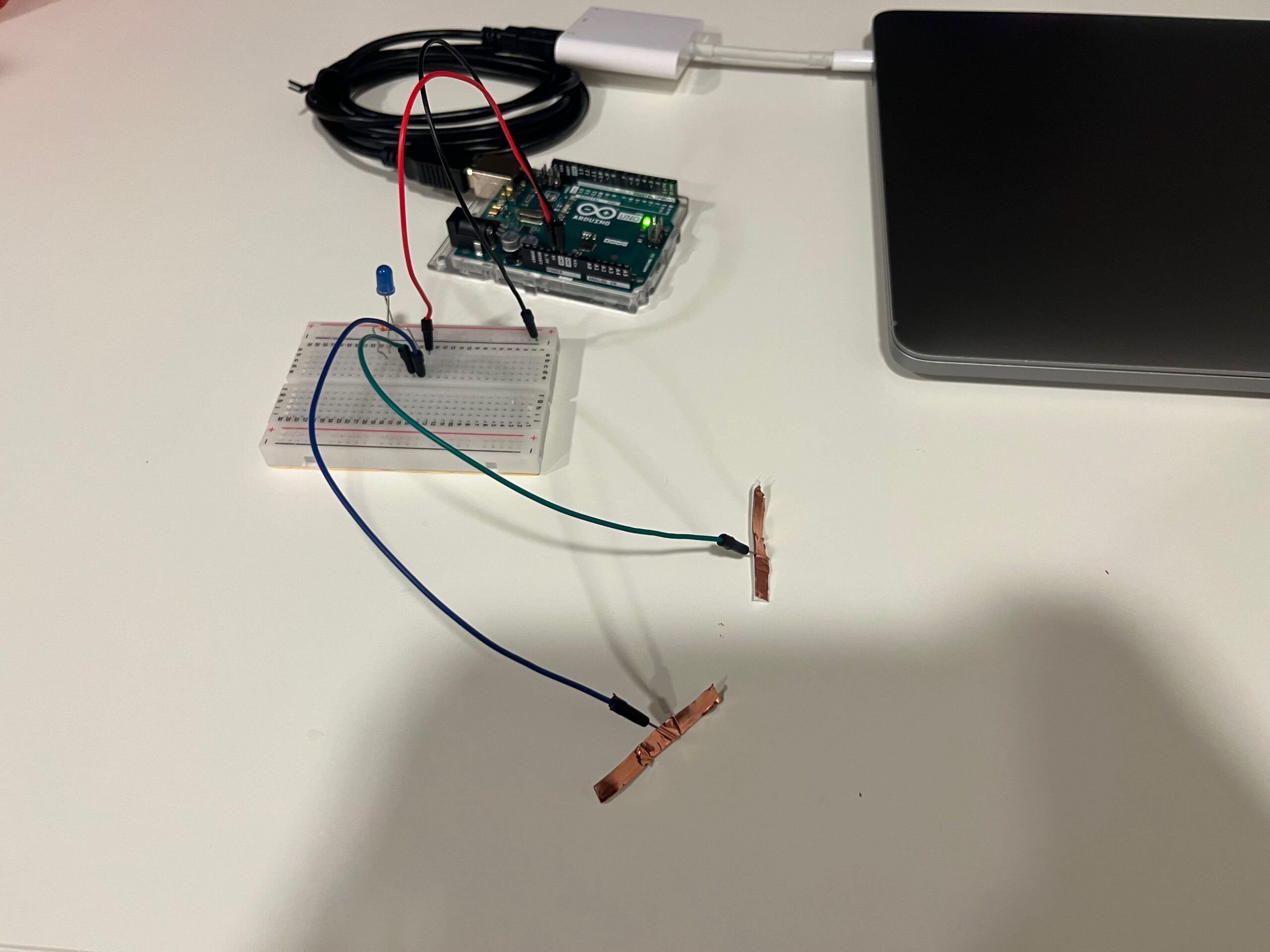
For this assignment, I didn’t have many ideas, so I was thinking about how to make the switch useful in a way. I thought of a few things, but then saw that my classmates had already done them, so I tried thinking of something else. That’s when it hit me! There is nothing I hate more than forgetting to wear my jewelry, particularly my rings. When I leave my room without them, I just feel… naked? However, one thing I never forget to do is to turn off the lights. I will always notice when a light is still on, unfortunately for me much more than when my rings aren’t. So, I thought, why not make a switch that is on when my jewelry is on it, and off when it isn’t? Obviously, this is a very small-scale prototype, but it was worth a try.
For the sake of the assignment, I only used one ring. It had to be a conductive material, so I picked a gold ring. Then, I created my circuit:
Although it’s not a very complex circuit, I enjoyed creating it, particularly because I had missed two classes and wasn’t sure I had understood the process well. But I’m glad it worked out!
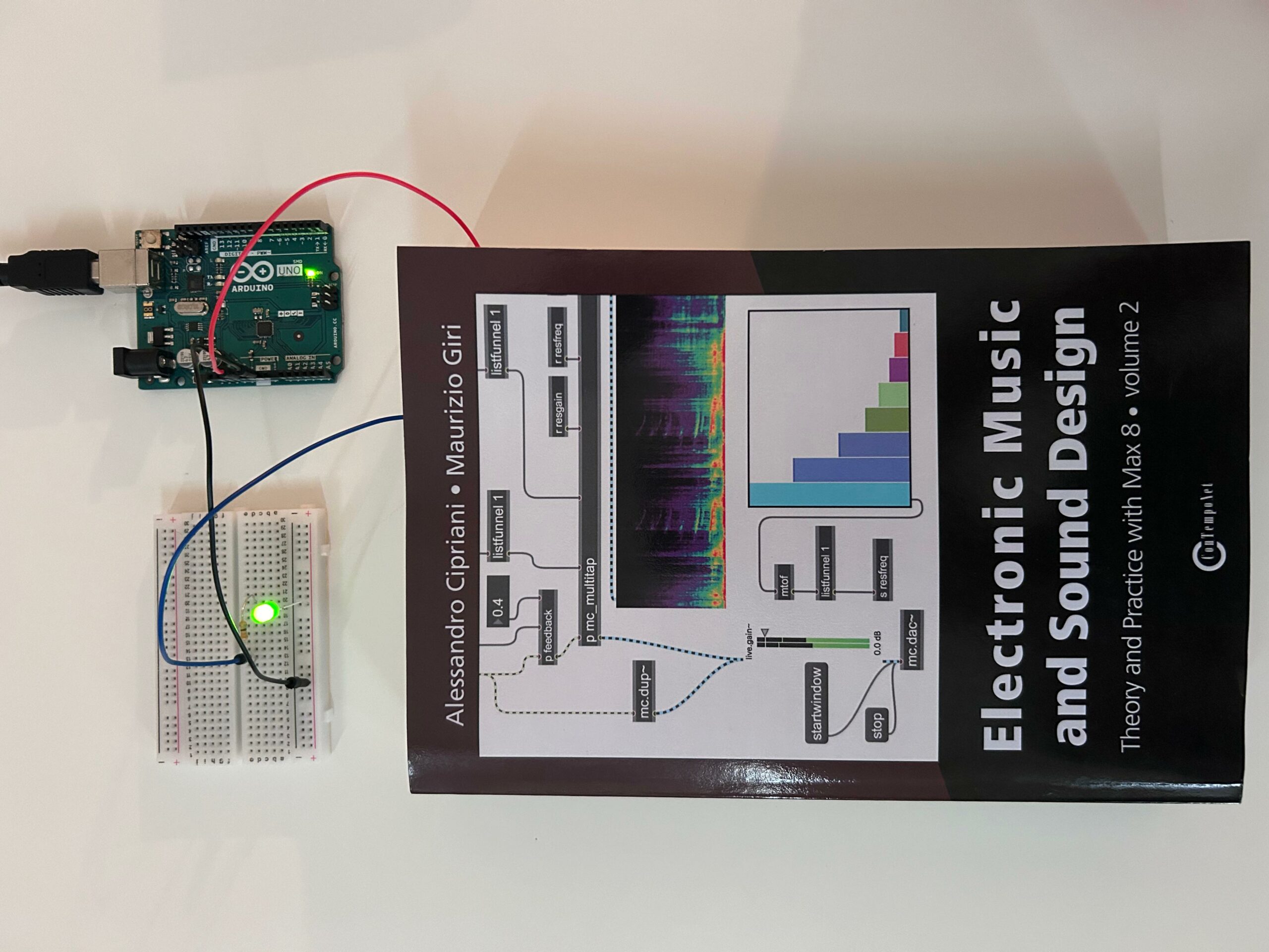
When I was sitting on my desk thinking of ideas for this assignment, the first thing that came to mind was a book I saw right in front of me (which I’m relying on the most lately for my another class).
Then, I realized I actually don’t have a bookmark and every time I’m reading a book, I just write the page on my phone. So I decided to create kind of a “bookmark” that turn on the LED every time I close the book.
Materials:
1 green LED light
1 330 ohm resistor
A breadboard
An Arduino board with the 5V and Ground outputs
1 red, 1 black, and 1 blue jumper wires
USB cable
Tape
My book
Demonstration:
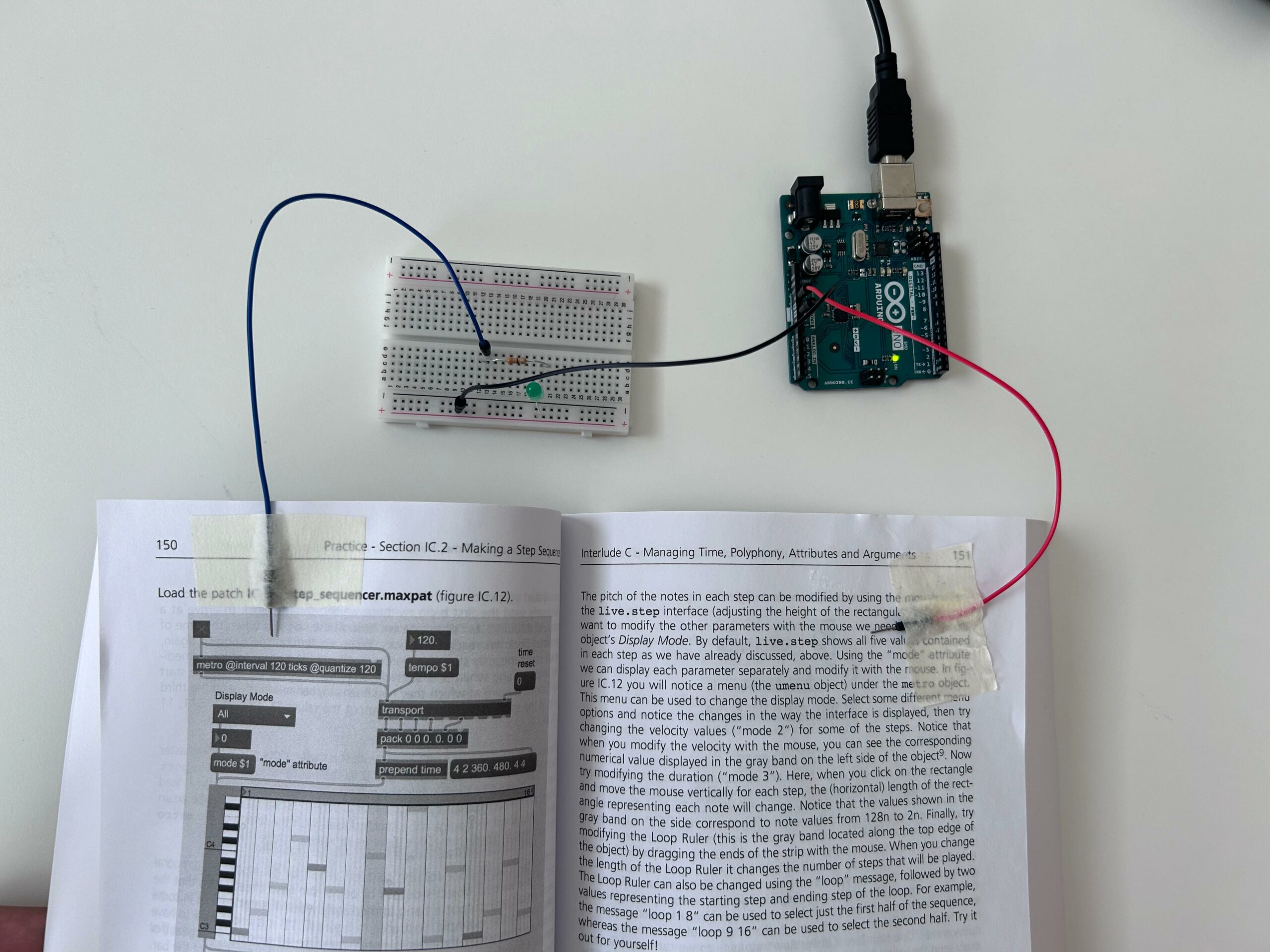
Process:
The process of this circuit is really simple. Basically, I connected two jumper wires in the 5 V and Ground outputs of the Arduino. However, instead of connecting the 5 V directly into the breadboard, I pasted in one of the pages of the book. Then I used another jumper wire to do the connection between the resistor and the 5 V output.
Circuit
Reflection:
I’m really satisfied with the outcome of the assignment, especially because I think experimenting is one of the best ways to learn Arduino. So, I’m getting more familiar with the logic and the process itself. When it comes to areas of improvement, I intend to explore more other materials, as well as other ways of connecting the circuit.
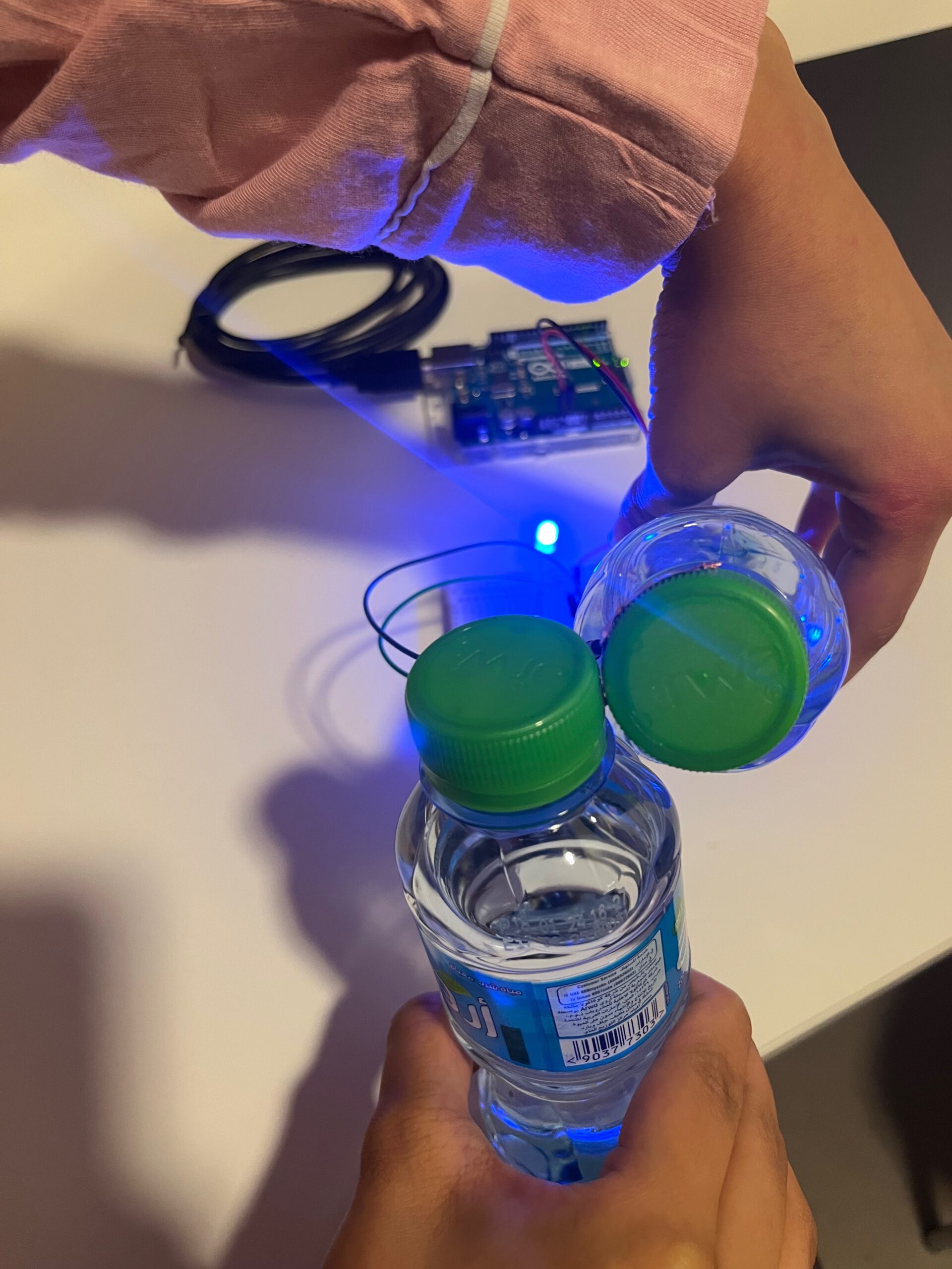
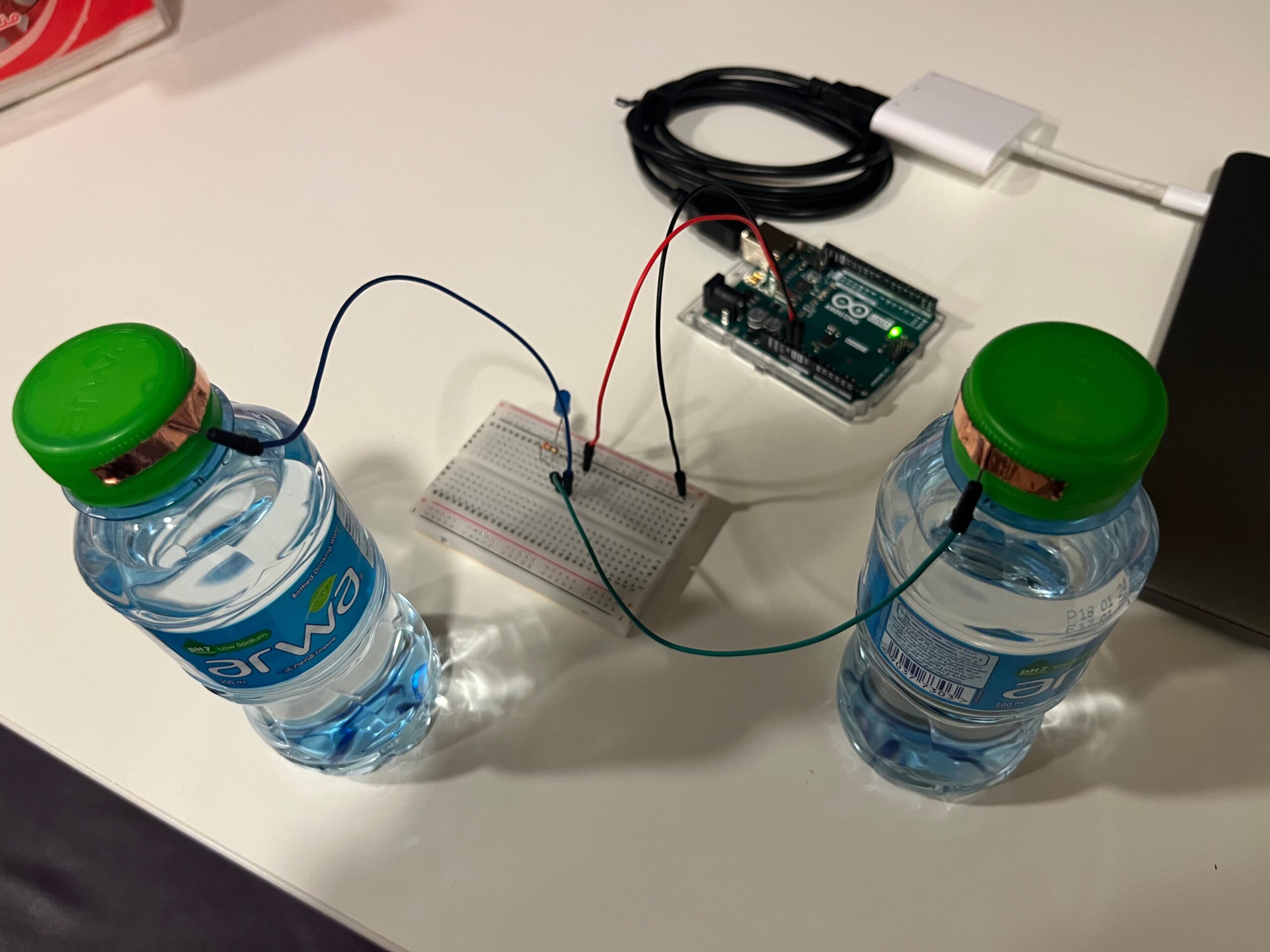
I first thought that it would be hard to find a case to switch the light bulb on without my hands but then the inspiration came to me when my friend sent me this emoji: 🥂. So I thought I could use water bottles to connect the circuit and switch on the light bulb. Which resulted in this:

 circuit built