Making Interactive Art: Set the Stage, Then Shut Up and Listen
This was a pretty interesting look into interactive media as a participatory media. Often artists tend to be afraid of their art being assigned a wrong meaning, and artistic clarifications usually keep popping up well after a work is created (JK Rowling is a particularly glaring example). It stems from a fear that our own beliefs, our own creation, will be inevitably challenged by the audience. This is even more true for something that involves even more two-way communication, like an interactive art showcase. Even in our own documentation, it is tempting to include an exact user guide of how to “use” our art. And while user guides are helpful for products, they might not have the same effect in art.
That is not to say however, that all interactive art has to be fully participatory and unscripted. This again goes back to the debate we had when discussing Chris Crawford’s The Art of Interactive Design. Once again, the question pops up of whether interactive is participatory, or whether it has to be organic. For example, a lot of games are deeply scripted, and while it may be argued that playing the game is an organic experience of its own, it doesn’t change the fact that in a lot of games, you will be seeing most, if not all, the events that are meant to happen. Visual novels are another example. By most definitions of interactivity, they are not interactive, being no better than picture books. Yet, they do feel interactive in their own way.
At the end of the day, it is up to the artist and what compromise they make between interactivity and meaning.
Physical Computing’s Greatest Hits (and misses)
This was a nice look at different classes of physical computing projects and the benefits and challenges of each. Usually, there seems to be a common theme where there is a compromise between implementation and engagement. Relatively simpler projects like the theremin, floor pad, video mirrors, and Scooby Doo paintings may be easier to implement and more common, but they also lose engagement quickly. On the other hand, more complex mechanical pixels, body/hand cursors, multi-touch interfaces and fields of grass may be more engaging but often run into implementation or maintenance issues that take away some of the charm. In a way, my main takeaway from the article was that rather than your physical computing mechanism, what is more important is the story and how the mechanisms tie in to the story being told.
For this project, I wished to use the ultrasonic sensor in some form, especially as it used to be my favorite sensor back when I experimented around with LEGO Mindstorms. I remembered that conceptually, a parking sensor was, in its simplest form, a combination of a digital input (Reverse Gear On/Off) and an analog input (ultrasonic/electromagnetic sensor). So, I decided to emulate that for this project.
Components
1 Arduino Uno R3 SMD
1 HC-SR04 4-pin Ultrasonic Distance Sensor
1 Slideswitch
1 Arduino Piezo Buzzer
1 10 kΩ Resistor
3 330 Ω Resistor
1 Red LED
1 Green LED
Jumper Wires (3 red, 5 black, 2 blue, 2 yellow, 2 white, 1 green [in lieu of black, as per convention])
Circuit Schematic and Simulation
The first step was to prepare a circuit schematic on TinkerCAD. Basically, the digital input took the form of a slideswitch feeding into a digital input pin (pin 12) through a 10 kΩ pull-down resistor. Analog Input (which I later discovered was actually a digital input) came from the Echo pin of the Ultrasonic sensor (pin 8), while the ultrasonic pulses were triggered from pin 9. Pin 7 and PWM Pin 5 controlled the digital-controlled Green LED and the analog-controlled Red LED respectively, while the buzzer output was from PWM pin 5.
TinkerCAD also has a handy simulation functionality, that even allows to upload the Arduino code and test how the circuit would work under simulator conditions. This definitely helped in fixing bugs before even testing with the actual circuit, and also helped to individually simulate each component before assembling together.
Usage and Implementation
So, the “parking sensor” is first switched on with a slideswitch, which simulates the gear being changed. The green LED turns on, indicating that the sensor is now switched on.
The analog part works by taking the reflection times reported by the ultrasonic sensor, which is converted to distance using the speed of sound. The distance is mapped to the brightness of the red LED and the frequency of repetition of beeps from the buzzer.
The circuit was assembled almost identically to the above schematic. As I had run out of black jumper wires, I substituted using a green jumper wire, as per convention. No other connections made use of green jumper wires. Other than the convention of red for live / black for neutral, I had additional conventions of my own: blue for inputs, white for digital outputs, and yellow for analog outputs.
//Global
int distance = 0;
int duration = 0;
int brightness = 0;
int minDistance = 5;
int maxDistance = 30;

//Pins
int digitalIn = 12;
int trigger = 9;
int echo = 8;
int green = 7;
int red = 5;
int buzzer = 3;

// Ultrasonic Function
long readUltrasonicDistance(int triggerPin, int echoPin)
{
  pinMode(triggerPin, OUTPUT);  // Clear the trigger
  digitalWrite(triggerPin, LOW);
  delayMicroseconds(2);
  // Sets the trigger pin to HIGH state for 10 microseconds
  digitalWrite(triggerPin, HIGH);
  delayMicroseconds(10);
  digitalWrite(triggerPin, LOW);
  pinMode(echoPin, INPUT);
  // Reads the echo pin, and returns the sound wave travel distance in centimeters
  return 0.01723 * pulseIn(echoPin, HIGH);
}

void setup()
{
  pinMode(digitalIn, INPUT);
  pinMode(green, OUTPUT);
  pinMode(red, OUTPUT);
  pinMode(buzzer, OUTPUT);
  Serial.begin(9600);
}

void loop()
{
  if (digitalRead(digitalIn) == HIGH) {
    digitalWrite(green, HIGH);
    distance = readUltrasonicDistance(trigger, echo);
    if (distance < maxDistance && distance != 0) {
      duration = map(distance, 0, maxDistance, 5, 60);
      brightness = map(distance, 0, maxDistance, 220, 0);
      analogWrite(red, brightness);
      tone(buzzer, 523); // play tone C5 = 523 Hz for 100 ms
      delay(100);
      if (distance > minDistance){
        noTone(buzzer);
        delay(duration); // Wait for (duration) millisecond(s)
      }
    } else {
      analogWrite(red, 0);
      noTone(buzzer);
    }
    Serial.println(distance);
    delay(10); // Wait for 10 millisecond(s)
  } else {
    digitalWrite(green, LOW);
    analogWrite(red, 0);
    noTone(buzzer);
  }
}
The code is not too different from the examples we did in class, other than the function for the Ultrasonic Sensor. For that, I followed this helpful tutorial on the Arduino Project Hub.
Showcase
Reflections
I enjoyed working on this project, although figuring out the Ultrasonic Sensor and debugging it did take a while. I was actually impressed by how sensitive the sensor turned out to be, and how it managed to sense even objects passing perpendicular to its field of view (as demonstrated towards end of demo). Thus, other than being a parking sensor, it does actually work as a rudimentary safety sensor, being able to detect pedestrians as well.
I originally wished to include another LED (a yellow one that would fade with distance and a red that would trigger at a threshold minimum distance), but I ran out of black jumper wires and viable space on the breadboard, so I cut it down to two. Also, not shown in the showcase itself is an issue that the circuit has with powering off. Possibly due to the built-in delays, it takes a while between the switch turning to off position and the LEDs themselves actually turning off.
Also, I realized only later that Ultrasonic Sensors technically are digital inputs, but since they transduce an analog measurement into a digital input, I felt that it worked for the scope of this project.
For this assignment, I wanted to recreate the human pulse / heartbeat. The blinking of the LEDs represents the ‘lub-dub’ sound of our heartbeat and the sound of the piezo buzzer represents our heart rate or pulse. When the button is pressed, the LEDs blink in a pattern synchronized with the buzzer. The potentiometer enables users to adjust the speed of the blinking pattern and the pitch of a piezo buzzer. So turning up the potentiometer symbolizes increasing the heart rate.
Video:
Schematic Diagram:
Arduino Code:
const int buttonPin = A2;
const int potentiometerPin = A0;
const int buzzerPin = 12;
const int ledPin1 = 7;   //red
const int ledPin2 = 8;   //green

int buttonState = LOW; //digital input
int potValue = 0;  //analog input
int blinkSpeed = 500; //LED blink speed

void setup() {
  pinMode(buttonPin, INPUT);
  pinMode(buzzerPin, OUTPUT);
  pinMode(ledPin1, OUTPUT);
  pinMode(ledPin2, OUTPUT);
}

void loop() {
  // Read the value of the potentiometer and map it to blink speed range (100-1000 ms)
  potValue = analogRead(potentiometerPin);
  blinkSpeed = map(potValue, 0, 1023, 100, 1000);

  buttonState = digitalRead(buttonPin);
  if (buttonState == HIGH) {  //button pressed
    blinkPattern();
    // Play a tone with frequency based on blink speed
    int buzzerFrequency = map(blinkSpeed, 100, 1000, 500, 1500);
    tone(buzzerPin, buzzerFrequency);
    delay(50);  // Buzz for 100 milliseconds
    noTone(buzzerPin);  // Turn off the buzzer
  } else { //button released
    digitalWrite(ledPin1, LOW);
    digitalWrite(ledPin2, LOW);
    noTone(buzzerPin);
  }
}

void blinkPattern() {
  digitalWrite(ledPin1, HIGH);
  delay(blinkSpeed);
  digitalWrite(ledPin1, LOW);
  digitalWrite(ledPin2, HIGH);
  delay(blinkSpeed);
  digitalWrite(ledPin2, LOW);
}
Overall, I am happy with the outcome. I was relieved to see it finally work because I was trying everything (debugging, restarting circuit, etc.) for 4 hours before I realized my 5V wasn’t connected in properly.
I further want to create more audio-visual displays using LEDs and the piezo buzzer.
In a sense, all art is interactive. The typical definition given to «interactive» is one that we have discussed in previous readings. As Chris Crawford had mentioned in «The Art of Interactive Design», he believes that interactive art is interactive when and only when both entities listen, think, and speak. Similarly, this is what the author of Making Interactive Art: Set the Stage, Then Shut Up and Listen» points to. The key here is to create a conversation, a dialogue between the artist and the viewer. When the artist over-interprets their own work, they force the viewer to listen and think in a certain way, without letting them speak.
In philosophy of art, what makes art different from other, technical, disciplines is that the process is part of the art. There are no pre-imposed rules to create art – the artist just creates as they go. This is where the place of the spectator is important. When there are no rules imposed, it means that the final result is never determined in advance. In that case, the whole process of creating an artwork becomes the artwork. The result becomes influenced by the interaction with the audience. And, even if there isn’t a visual shift after the audience’s reaction, it is the act of listening to your audience and letting them think and speak for themselves that conceptually alters the course of the artwork.
Reading about interactive art in “Physical Computing’s Greatest Hits and Misses” and “Making Interactive Art: Set the Stage, Then Shut Up and Listen” felt like peeking behind the curtain of a magic show. It made me ponder the fascinating dance between the artist, the artwork, and us, the audience, especially when technology joins the party.
One big question that popped into my head was: can an artist ever truly be the puppet master in this interactive playground? I mean, the moment you invite participation, you’re kind of handing over the reins, right? It’s like setting up a stage for improv – you provide the props and the backdrop, but the actors, well, they bring the story to life in their own unique way. And that’s pretty darn exciting, this unpredictability that makes each experience unique.
“Making Interactive Art” really struck a chord with me when it talked about setting the stage and then taking a step back. It’s like the artist is saying, “Here’s the world I’ve built, now come explore and make it your own.” This reminds me of those cool performance art pieces or happenings, where the lines between performer and audience blur, and everyone becomes part of the art. It’s all about embracing the unexpected, the happy accidents that make life (and art) so interesting.
There was this one bit in “Physical Computing’s Greatest Hits and Misses” that made me pause. It talked about how getting lost in fancy technology can actually be a trap. It reminded me that the heart of interactive art isn’t about gadgets and gizmos, it’s about the human connection, the emotions and thoughts it evokes. Like, a cool light show is fun and all, but if it doesn’t make you feel something, think something, then is it really art?
These readings have made me realize that the artist in interactive art is more like a gardener than a dictator. They plant the seeds, nurture the soil, but ultimately, it’s up to us, the audience, to help the garden grow. And that’s the beauty of it, this collaborative spirit that makes interactive art feel so alive, so human.
Now, I’m curious to see how artists can create these interactive worlds without being too controlling. It’s like finding that sweet spot where the artist’s vision meets the audience’s imagination, and together, they create something truly magical.
In this post, you will find each individual reading reflection assigned for week 10. These reflections will be mostly based on my experiences, so actual discussion on the contents of the writing will be somewhat limited since I feel that it would be redundant to summarize what is there.
Making Interactive Art: Set the Stage, Then Shut Up and Listen
Generally, I associate the term Interactive Art with video games. According to the article, we are not supposed to readily give interpretation of our own works due to possibly adding bias and making boring the interactive experience for others. For example, in mysterious abstract video games, I have seen authors avoid giving full explanations to seemingly inconclusive questions in order to keep conversations, theories, and engagement alive. In a confusing title such as OFF (Mortis Ghost, 2008) the world that it presented is full of mysterious elements. At first sight is difficult to give an explanation to, nevertheless it invites the player to give its own reasoning to this interactive art.
As for other interactive art mediums, I often found myself walking on the corridors of the Arts Center building to see some interesting digital arts, such as a screen that portrays me in symbols. There are many other examples, but what they have in common is that they apply the concept of “show, don’t tell” that I really love about video games, since it leaves the spectator/player alone with the interactive art. In other words, it is a personalized experience: I will find an interactive digitalized portrait of myself super thought-provoking, while a friend could just find it funny. Different experiences, but there is not a fixated idea due to not having the author directly explain it to us as to why the existence of the created interactive art.
Physical Computing’s Greatest Hits (and misses)
During my time as a child, I have seen a correlation between success and devices that challenge pre-established formulas. For example, in today’s world (today as at the time I am writing this) computer mouses are generally used due to facilitating the computer experience, it facilitated it so much that the entire computer GUI landscape adapted to it. It acts as a “third hand” that gets materialized into the digital world, where if you want to “grab a file”, you just have to hold the mouse with one of your fingers in order to simulate the action of grabbing. It was a great hit, but what about other technologies that try to revolutionize or seek general fun?
I would like to imagine a James Bond like hand watch as a replacement for the watches we have now, such as the Apple Watch. One finds (small) pleasure in using the watch to quickly watch the time and timely arrange the next activities to do, as well as it also looks and feels nice to have due to the possible elegance it possesses. But what about making it a very curious device, such as the one that James Bond has? Imagine this: you have a clock that looks impressive, thus it is pleasurable to wear, but also has a laser, camera, and magnetism included on it. Yes, one can easily argue that this idea is already done to death in many series and movies as an inspiration, but still, one can find other workarounds to this theoretical watch; a remix act. So, instead of creating an actual James Bond like that shoots lasers, what about throwing confetti in miniature? One could find pleasure in annoying friends and family with the functionality.
In conclusion, I found this article curious as I noticed some patterns in successful products, such as the indirectly mentioned Dance Dance Revolution Dance Pads in the writing. The world of physically interactive art has its market, because it is pleasurable and fun to experiment with items one might never be seen before.
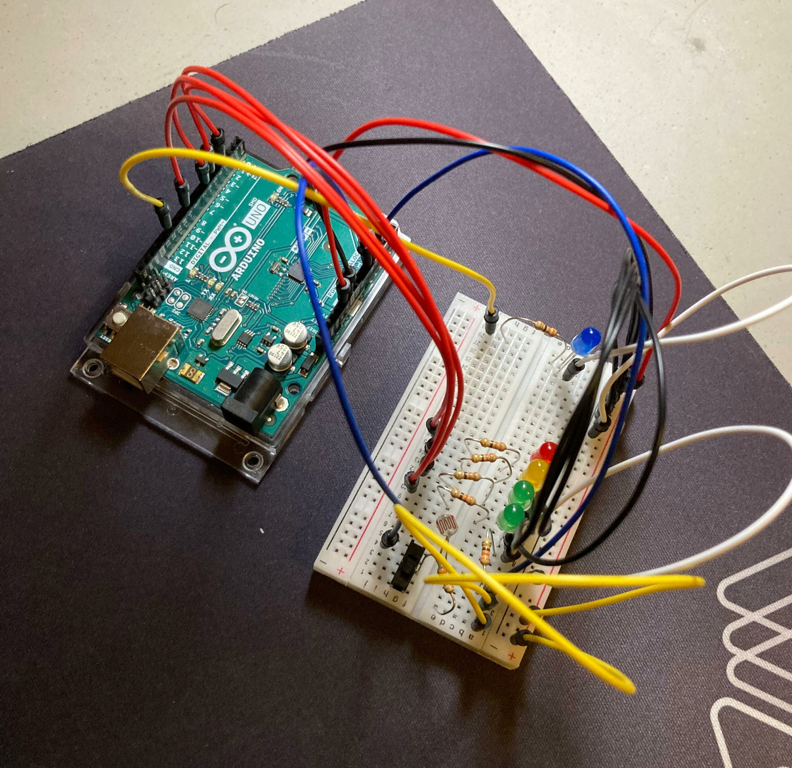
For this week, I tried to imagine something complex to do, but due to creative bankruptcy, I could not imagine any interesting mechanisms for this Arduino. Although, I still wanted to experiment with what we have learned in class so far.
When we were experimenting with the photoresistor, I was curious to see what kind of patterns I could make with the use of the device, LEDs, and the mapping function. Thus, I came with the idea of doing a volume meter inspired light detector.
Figure #1: Arduino made in person.
Materials
7 330-ohm resistors.
2 green LED lights.
1 yellow LED light.
1 red LED light.
1 blue LED light.
A breadboard.
8 red jumper wires (due to being low in red jumper wires, three are yellow).
7 black jumper wires (again, due to being low, 2 are white).
2 blue jumper wires.
An Arduino board with, 5V, GND, analog and digital output and input.
A slideswitch.
Implementation & Usage
Once all the materials are set up like in the schematic and the Arduino is powered, the user can do either of the following according if the slideswitch is ON or OFF:
1. If the slideswitch is ON, a blue LED will indicate this state. In this mode, if a light source is redirected to the photoresistor, the LEDs will turn on, like a volume meter, depending on the strength of the source.
2. If the slideswitch is OFF, the blue LED light will be off, indicating this state. In this mode, a non-interactable sequence where each LED light will be displayed, where they will be turning ON and OFF in a 0.5 second basis.
Both modes can be interrupted at any time.
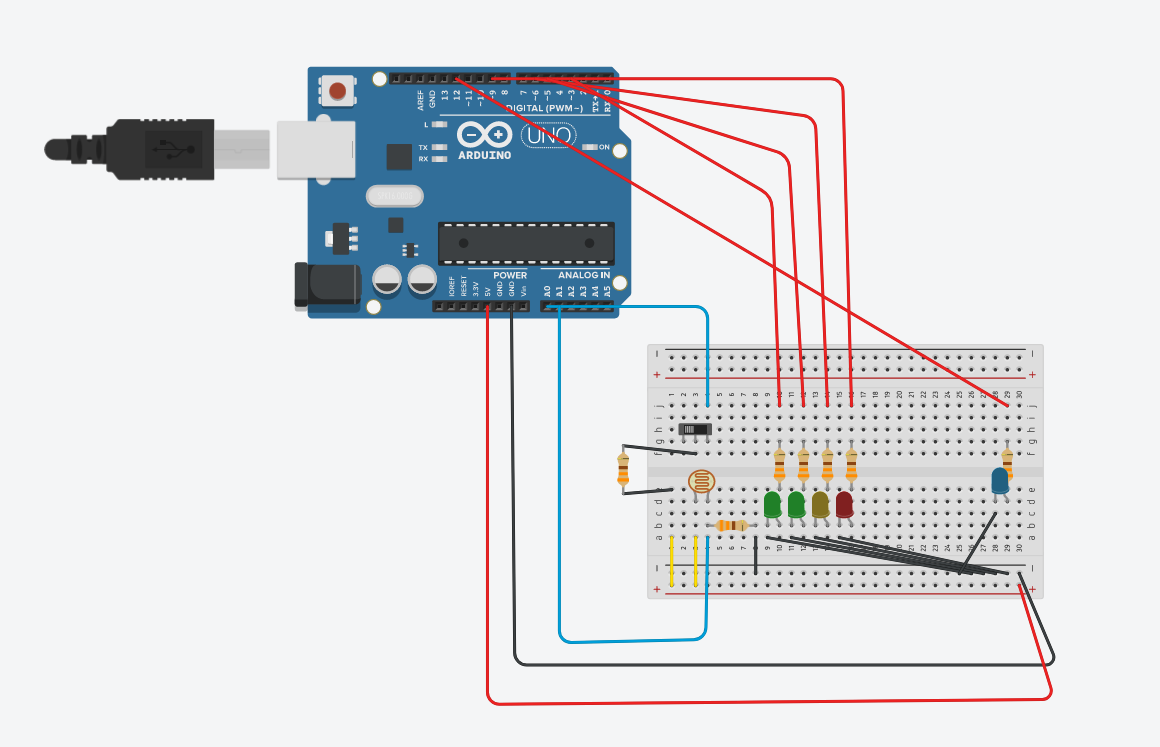
Schematics
Figure #2: Schematic #1 made in Tinkercad.
Figure #3: Schematic #2 made in Tinkercad.
Code
For the coding, I used the blocks GUI from Tinkercad, and then transform it into code to change it according to my necessities, as well as add some comments to it to further explain some functionalities.
//We will only use two variables for this Arduino set up:
//Brightness is to receive the analog values from the photoresistor, to use to turn ON the LEDs.
//Switchstate will alternate between states depending on the analog valaue received.

int brightness = 0;
int switchstate = 0;

void setup()
{

  // Preparing the Arduino and variables initialization.
  pinMode(A0, INPUT);
  pinMode(A1, INPUT);
  Serial.begin(9600);
  pinMode(3, OUTPUT);
  pinMode(5, OUTPUT);
  pinMode(6, OUTPUT);
  pinMode(9, OUTPUT);
  pinMode(12, OUTPUT);

  brightness = 0;
  switchstate = 0;
}

void loop()
{
  switchstate = analogRead(A0);

  // According to the amount of light received by the photoresistor, it will turn on the LEDs. For example,
  //if the light source is too strong, all LEDs will turn on, if it is too low, either 1 or 2 will be ON.

  if (switchstate > 1013) {
    digitalWrite(12, HIGH); // Blue LED indicates light mode.
    brightness = analogRead(A1); //Receive values from the photoresistor.
    Serial.println(brightness); //and print it to serial.
    if (brightness > 100) {
      analogWrite(3, map(brightness, 0, 1023, 0, 300)); //First green LED will be turn on and its intensity will depend on the intensity of the light source. Also, we map the values received since if it is too high, then it will basically loop; mapping makes sure that it always states in a range.
      if (brightness > 200) {
        analogWrite(5, map(brightness, 0, 1023, 0, 300)); //Second green LED will be turn on and its intensity will depend on the intensity of the light source. The rest is the same.
        if (brightness > 300) {
          analogWrite(6, map(brightness, 0, 1023, 0, 300));
          if (brightness > 400) {
            analogWrite(9, map(brightness, 0, 1023, 0, 300));
          } else {
            digitalWrite(9, LOW);
          }
        } else {
          digitalWrite(6, LOW);
        }
      } else {
        digitalWrite(5, LOW);
      }
    } else {
      digitalWrite(3, LOW); //If it fails to meet the requirement, the it will turn OFF without exceptions. It is the same for the rest of LEDs.
    }


  } else {
    // Each LED gets turn on and off in order.
    digitalWrite(12, LOW); // Blue LED gets shut down.
    digitalWrite(3, HIGH);
    delay(500); // Wait for 500 millisecond(s)
    digitalWrite(3, LOW);
    digitalWrite(5, HIGH);
    delay(500);
    digitalWrite(5, LOW);
    digitalWrite(6, HIGH);
    delay(500);
    digitalWrite(6, LOW);
    digitalWrite(9, HIGH);
    delay(500);
    digitalWrite(9, LOW);
    Serial.println(switchstate);
  }
}
Showcase
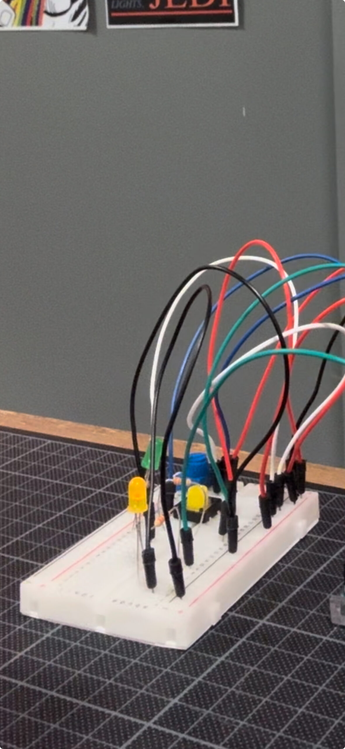
In this video, I show how the Arduino looks and operates. Please keep in mind that the color of some jumper wires had to be mixed up (at least strategically) due to material constrains, in order to still convey the positive and negative connections.
Challenges
The biggest challenge in this Arduino was, actually, making the photoresistor to work. The reason of this difficulty was that I had forgotten how to set up the photoresistor properly, even though we were taught how to do so in class. Although, with a YouTube video and quick review of the slides, I was able to pick up again what I needed to do and not question myself why I was getting a consistent analog value of 1024 from my photoresistor.
Reflection
I am feeling that I am going a bit bankrupt creatively. I do admit that this Arduino took me time to develop, but the many ideas I had in my mind are still not able to come into fruition. Likewise, I personally feel that this is like the previous scenario in the first half of this semester, where I was mostly experimenting with the provided tools in order to have a greater idea of what is possible to do. It is likely it will happen in this case, but still, I wish I could come with more ideas to develop more curious devices.
Nevertheless, I did learn something new from this Arduino, like how to effectively map some values and how to set up properly a device (ignoring the selection of colors of the jumper-wires of course) to capture values from two points: the photoresistor and the slideswitch.
I although I find that the subject of “Making Interactive Art: Set the Stage, Then Shut Up and Listen” is well meaning, it think that to an extent, it misses the reason why some artists interpret their own interactive works.
Coming from a mainly computer science background, its hard for me to see my programs being misused in a way that I did not intend. To me, this feels like failure, which in a way it is, as I have failed to design a program which accurately and correctly executes what it is supposed to. This is why I emphasize with artist who offer interpretation notes beside their work, as they too are hoping that it will be used or viewed in the “right” way, the way that they intended, as a way to prevent their “failure”.
However, the big difference here is that what they are doing is art, and not computer science. In computer science, the focus is often on precision, functionality, and predictability. A program that doesn’t work as intended is considered flawed and needs debugging or refinement.
Art, on the other hand, often thrives on ambiguity, interpretation, and the emotional response it elicits from its audience. Interactive art, especially, invites the audience to engage with it, to become part of the artwork’s evolution and meaning. This inherently means that the artist relinquishes some control over the final outcome.
When an artist provides interpretation notes or guidelines alongside their interactive art, it can be seen as a way to guide the audience’s experience or to share their perspective. However, it’s essential to remember that art is subjective. Each viewer brings their own background, experiences, and emotions to their interpretation of the artwork. This diversity of interpretation can enrich the artwork’s meaning and create a more profound connection between the viewer and the art.
Rather than viewing unintended interactions or interpretations as failures, artists can see them as opportunities for growth, learning, and further exploration of their art’s potential. It can lead to unexpected outcomes that even the artist hadn’t considered, expanding the artwork’s scope and impact.
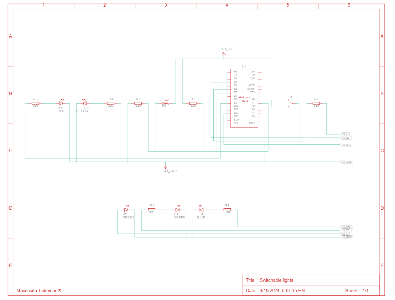
For this assignment, I wanted to make something a bit funny. Thus, I decided to make a light switch powered by light. My idea was simple, point an LED at an LDR, record its readings, and light up another LED at the brightness the LDR recorded.
Unfortunately, after building by circuit, I ran into an issue with the Arduino, where it would not read anything from the IN pins and would not allow me to print anything to the terminal either.
Not to be discouraged, I decided to build the entire circuit in analog.
Had I been able to use the analog IN pins, my code would have looked like this.
// Define the LDR pin
const int ldrPin = A0;
// Define the digital LED pin
const int digitalLedPin = 13;

// Variable to store the LDR value
int ldrValue = 0;

void setup() {
  Serial.begin(9600);
  pinMode(digitalLedPin, OUTPUT);
}

void loop() {
  // Read the analog value from LDR
  ldrValue = analogRead(ldrPin);

  // Print the LDR value to Serial Monitor
  Serial.print("LDR Value: ");
  Serial.println(ldrValue);

  // Set the brightness of the digital LED based on the LDR value
  analogWrite(digitalLedPin, map(ldrValue, 0, 1023, 0, 255));

  // Add a delay to avoid flooding the Serial Monitor with data
  delay(500);
}
Additionally, I noticed that the who design does not work very in lit environments, so I wanted to add a function which would calculate the average light in a room, and set the output LED to 0, so that a change in lighting from the other LED would be more noticeable. This, however, is impossible to do with my understanding of analog circuits.
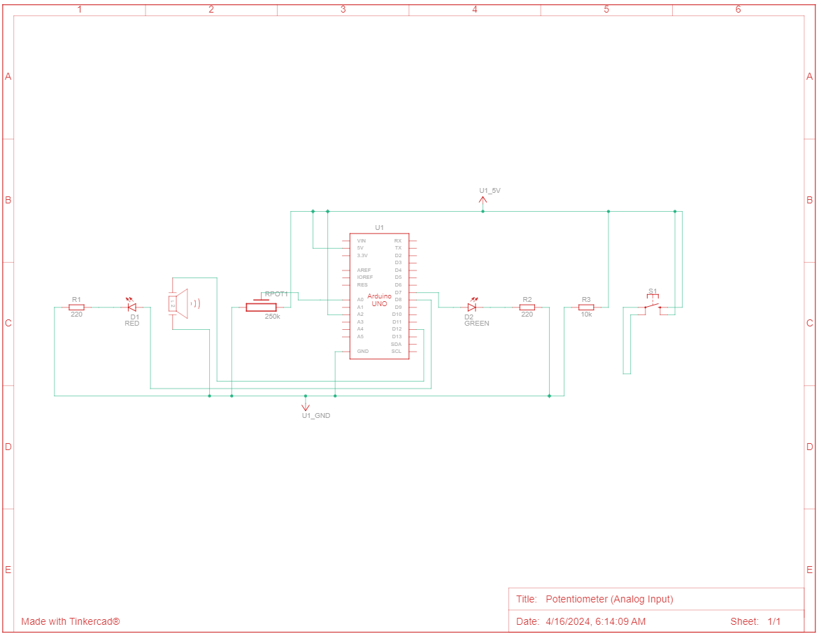
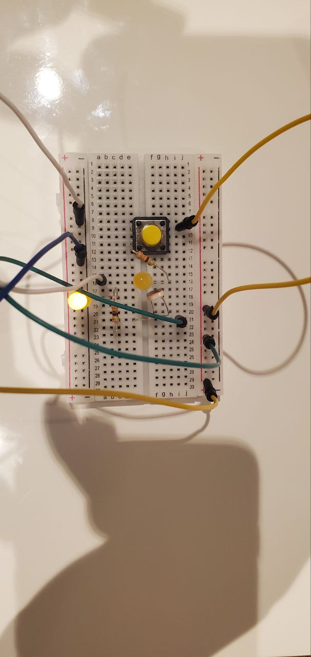
For this week’s assignment, I used potentiometer as an analogue sensor, and a tactile button as a digital sensor (switch) and two LEDs. For the LED that is controlled by the tactile button, I made it so that it blinks twice and the potentiometer for brightness control.
Code:
int led = 11;
void setup() {
  // initialize digital pin LED_BUILTIN as an output.
  Serial.begin(9600);
  pinMode(led, OUTPUT);
  pinMode(8, OUTPUT);
  pinMode(A2, INPUT);
}

// the loop function runs over and over again forever
void loop() {
  int button1State = digitalRead(A2);
  int sensorValue = analogRead(A1);

  Serial.println(sensorValue);

  analogWrite(led, sensorValue/4);
  delay(30);

  if (button1State == HIGH) {
    digitalWrite(8, HIGH);
    delay(1000);
    digitalWrite(8, LOW);
    delay(1000);
    digitalWrite(8, HIGH);
    delay(1000);
    digitalWrite(8, LOW);
    delay(1000);

  } else if (button1State == LOW){
    digitalWrite(8, LOW);
  }

}

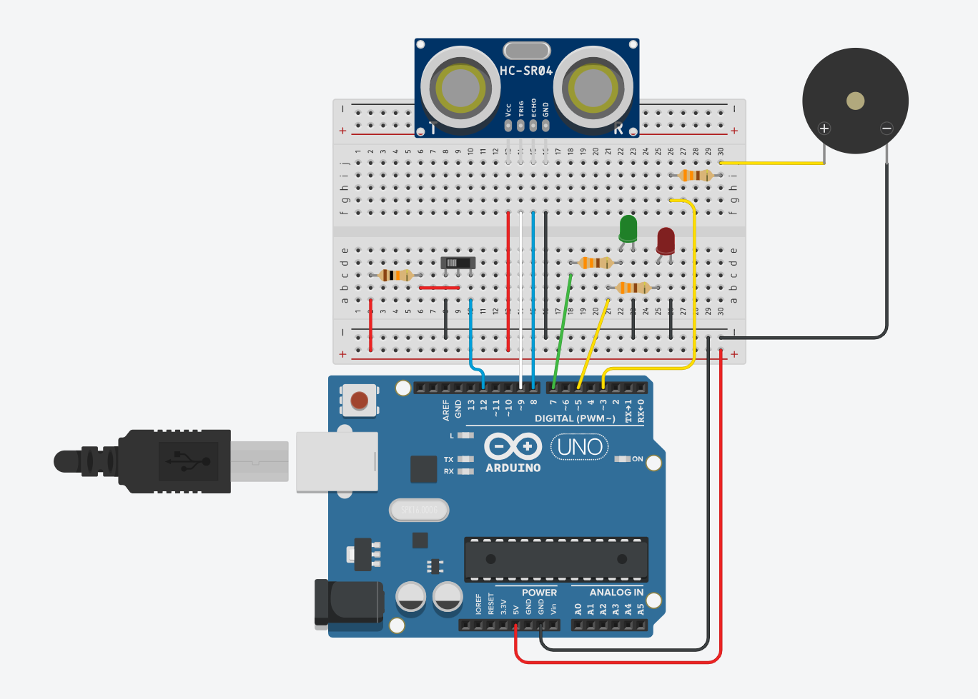 Figure 1: Component Simulation View
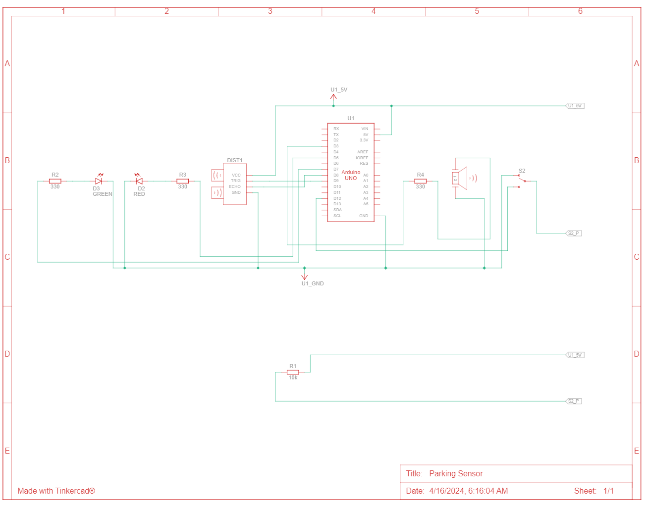 Figure 2: Schematic View
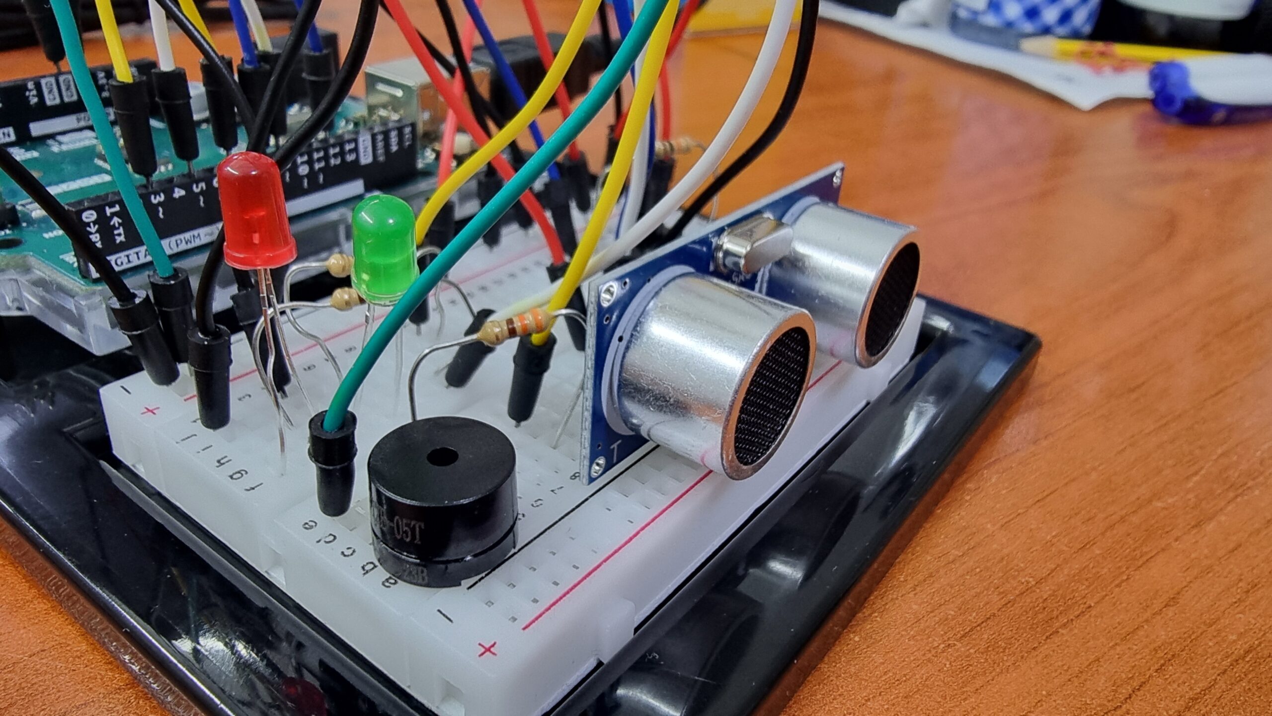 Figure 3: Front View
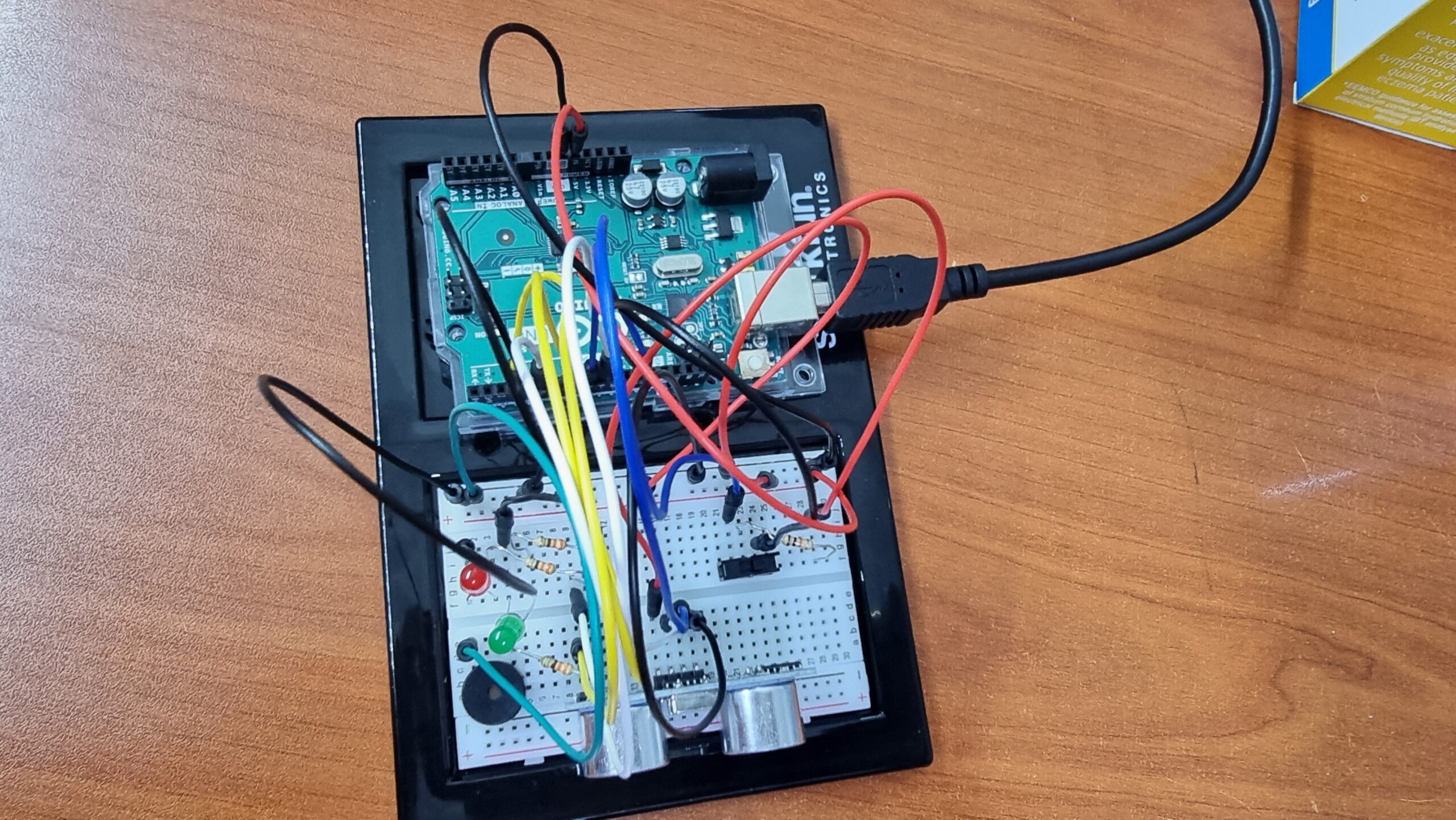 Figure 4: Top View
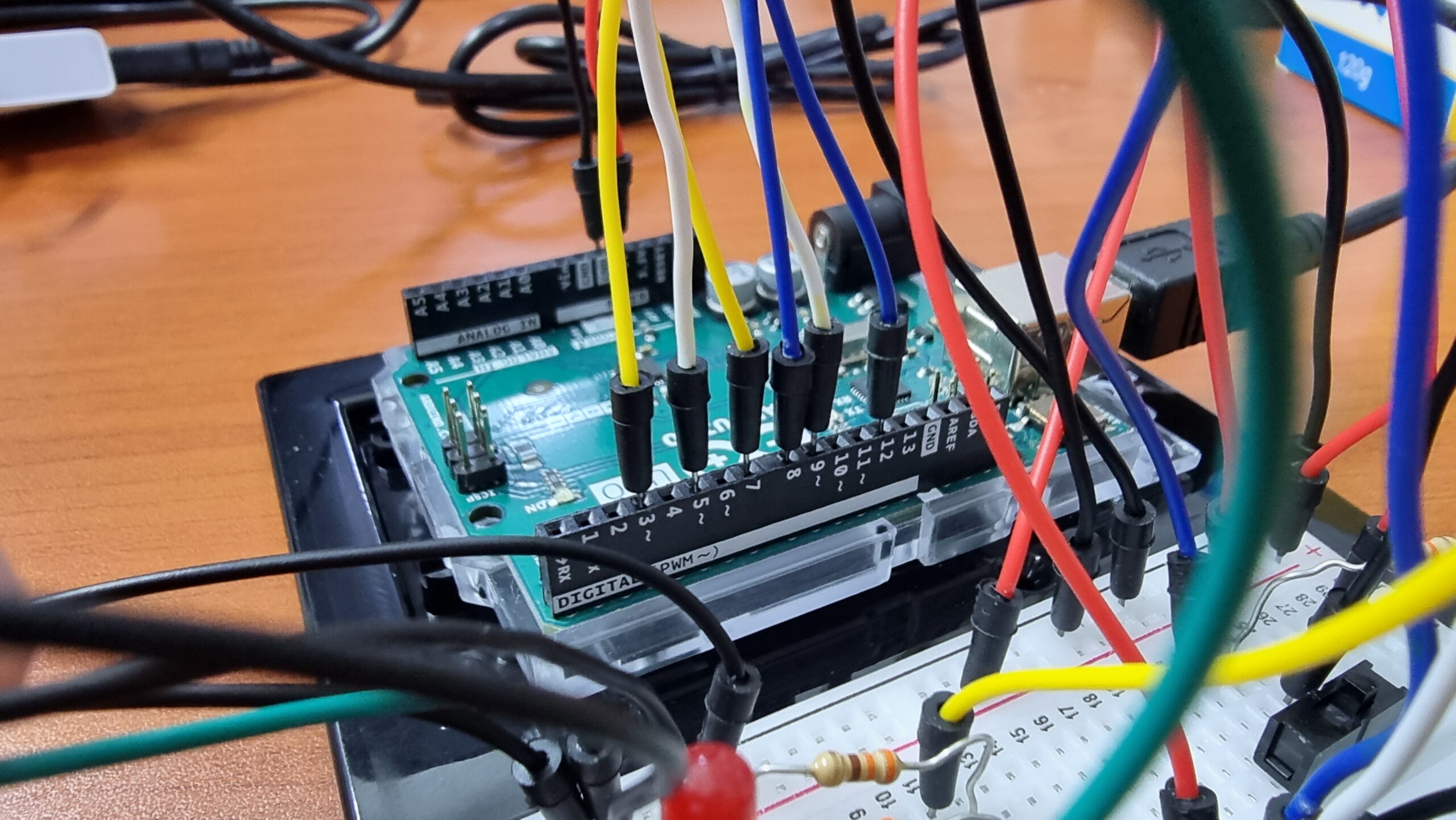 Figure 5: Arduino Pins Connection