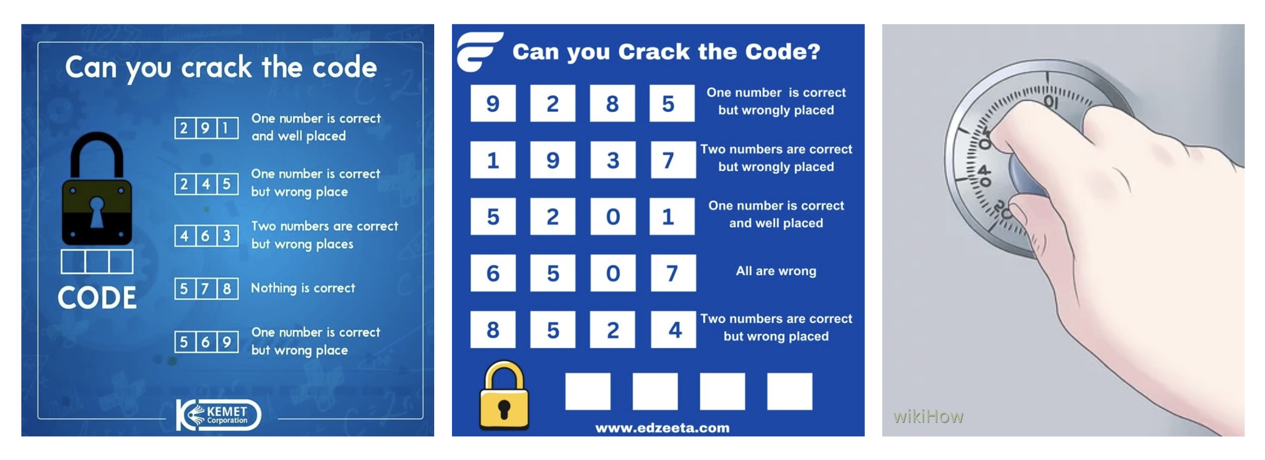
“The Heist: Unlock the Safe” is an exciting puzzle/math game that challenges your mind to decode a sequence of numbers given a few hints, with each of them guiding you in eliminating potential numbers. It’s pretty simple, the user is provided with instructions which then allows them to use their skills and crack the code. The theme behind it is to provide a sense of thrill of cracking a safe, just like in a bank robbery (not advised) or an escape room!
DOCUMENTATION
1) Teaser Video (pre-showcase)
2) Demo Video (how to play?)
3) Final video (showcase day!)
IMPLEMENTATION
Interaction Design
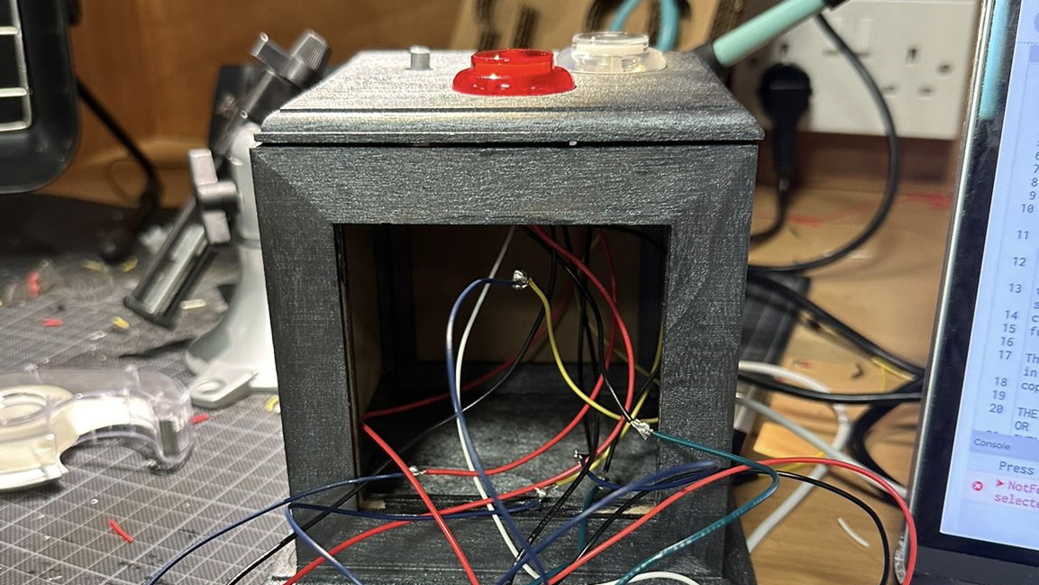
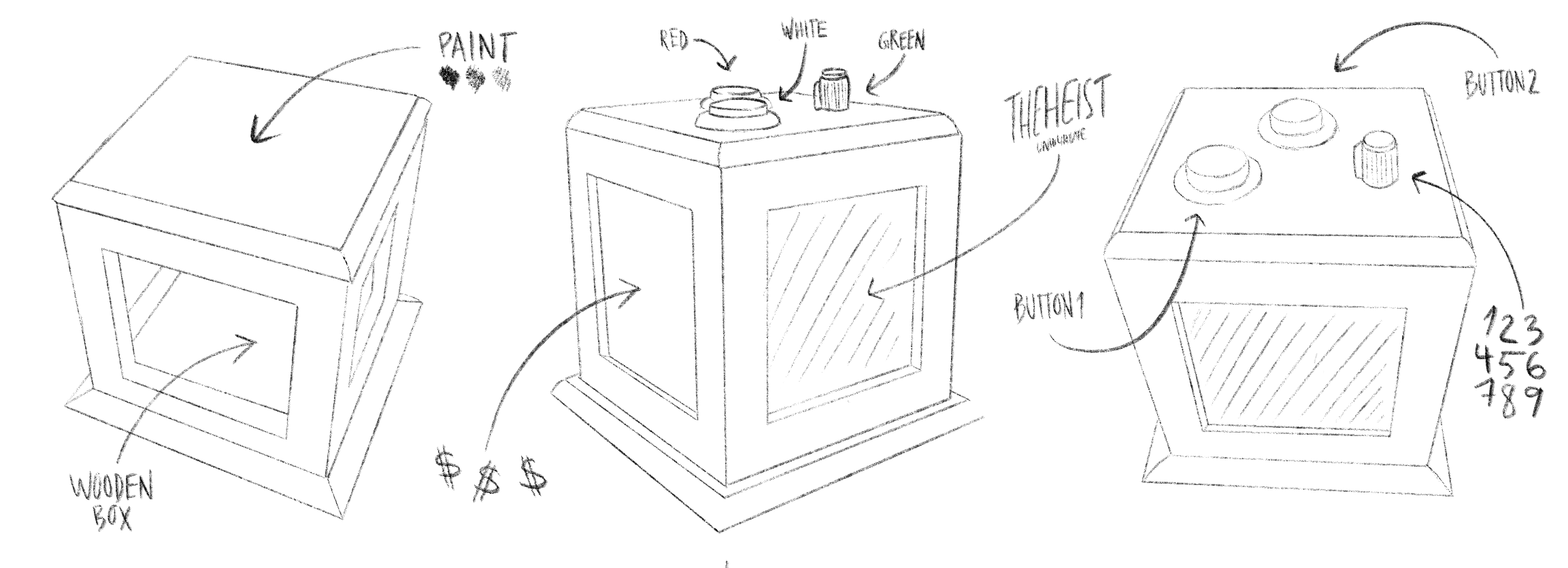
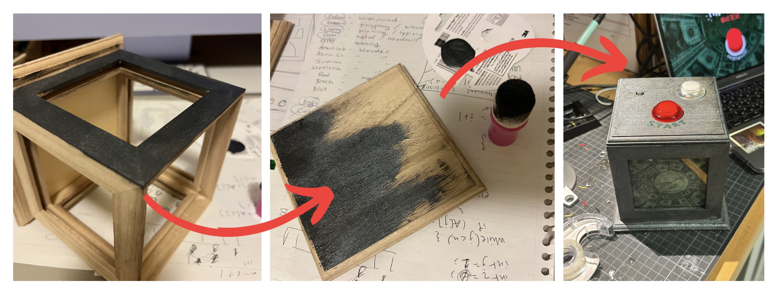
The box I created features two buttons and a potentiometer, positioned for user convenience. The red button, placed farthest from the user, serves as the game initiator and state mover, designed for occasional use. On the other hand, the knob (potentiometer) & white button are situated closer to the player, allowing easy access as they will be frequently used during the game to guess the code. Further, the box was designed to match the game’s theme, in terms of color and aesthetic (materials used: wood, wood paint, sponges, tape, glue, equipment, etc.).
Arduino
The Arduino code sets up the game with a three-digit combination lock (three possible combinations). It initializes variables such as the game state, the entered codes, and the correct combination. The safe can be in the following states: Menu (‘M’), Instruction (‘I’), Play (‘P’), and End (‘E’). Buttons and a potentiometer are used to input digits, and a servo motor controls the lock mechanism. The program continuously checks for button presses, serial input, and the correctness of the entered code. If the correct code is entered, the safe unlocks the servo motor, indicating success. Otherwise, it remains locked, prompting the user to retry. However, it’s worth noting that the initial plan to control the lock mechanism with the servo was later removed from the code. The checkCode() function, verifies if the entered code matches the correct combination when the game state is ‘E’ (End). It iterates through each digit of the entered code, comparing it with the corresponding digit in the correct combination. If any digit doesn’t match, it sets the correct flag to false and breaks out of the loop. If all digits match, meaning a correct code, it unlocks the safe by setting locked to false and open to true. Link to Arduino Sketch.
P5.js
The p5.js code begins by declaring variables such as various image files required for the game. Key components for communicating with an Arduino are included, such as variables to read data from Arduino (digit, button1, button2, locked) and variables to send data to Arduino (open, codes, button1State, button2State, buttonPressCount). The `keyPressed()` and `preload()` functions handle necessary setup tasks, such as loading sound and image files. The `setup()` function initializes the canvas and starts the game by calling the `restart()` function. The `draw()` function renders different game screens based on the current `gameState`, which then displays images accordingly. The `readSerial()` function manages data received from the Arduino, updating game variables accordingly.
Communication
At first, I used one button for both entering digits and moving to different game parts. But p5.js got mixed up with the signals from Arduino. So, I split the tasks between two buttons. Now, one button only enters digits (white button), and the other button (red button) handles moving between game states. In the communication between the Arduino & p5.js, the serial monitor informs p5.js about the status of buttons and the number from the potentiometer. Each line of data received has four parts (initially): two “true/false” statements indicating button states, followed by numbers representing the potentiometer reading. Using this data, p5.js updates variables like `button1`, `button2`, and `digit`, which helps control the game. For instance, if `button1` is true and `button2` is false, it means a certain action from the player, like moving to the next stage or entering a code digit. Dealing with serial communication was certainly one of the challenges I encountered in the process.
PROUD MOMENTS
I am particularly proud of how the box turned out in terms of its design matching the game aesthetic. I am also proud of how much I have learned throughout the process and through many many many many mistakes that costed hours of my time, but it was all worth it. Safe to say, I’m almost fluent in Arduino. I was also proud of the short amount of time I had to work on it and pulled through hours on end in the lab, especially given that I had missed the class where soldering was practiced, so I had to figure that out with the help of endless YouTube videos. Surprisingly, I am glad that I did not add a time element to the game because some people were taking less than a minute while others more than 5; a time limit would not have been ideal, I believe. More than anything, I am proud of how this project has brought many of me and my classmates together, and I am happy with how it turned out. If you had told me that I’d do this on the first day of classes, I would not have believed it was possible!
AREAS OF IMPROVEMENT
I initially had more in mind, such that the box would unlock and a beam of light would appear, or even better, serve some chocolate! Yet, I was faced with the unexpected measurement issue when the box was too small, and I underestimated how much space the wires would take. Regardless, I attempted to put something inside, and the wires kept moving and unplugging, leading to disaster every time I got close to it. To add to that, halfway through the showcase, the potentiometer stopped reaching the number 9, so I had to quickly edit my code & delete the possibility of a code generating a combination with the number 9. Other than that, it ran very smoothly. Another thing would have been to signify what the white button was, although many instinctively knew, given that the red button was labeled. Learned a lot, to say the least! Thank you!
“Design Meets Disability” was a really eye-opening read (pun intended). As we know, eyesight issues are common throughout the world, including myself. In recent years, there has been an explosion in the number of people wearing glasses. Although sight issues are increasing within the population, this isn’t the only reason why people are wearing glasses. Even with contact lenses or corrective surgery being a possibility for many people, lots of individuals are choosing glasses for fashion and stylistic reasons. To be specific, as of 1991, the design press declared that “eyeglasses have become stylish” (page 17). Even more than just eyesight problems, the book discusses many other physical disabilities such as hearing aids, where the company HearWear invested in its design unlike other companies. As Henrietta Thompson put it, “Over the decades, there has been an amazing amount of technical development of hearing aids, but in that time little or no design investment occurred” (page 25). I believe the reason is that they have focused much more on the technology and developing it more precisely, as they may be more complex than eye lenses.
Moving onto body wear, leg wear, and prosthetics, the book claims that there are only two approaches, which include realism and functionalism (page 35). In an increasingly complex world, we must value, as the author said in page 64, the word design in “designing for disability.” As a matter of fact, when googling “designing for disability,” the first thing that pops up is “To design for disability means giving your users control and options.” See, that’s the misunderstanding; there’s a huge focus on functionality that disregards design. Designing for disability isn’t as inclusive and thoughtful as I had assumed, and looking ahead, I’m hopeful for a future where designing for disability embraces creativity, to hopefully empower individuals of determination not to feel ashamed but to serve as inspirations for us all. I’m not sure if it was mentioned, but I wonder what the author’s take would be when it comes to braces or getting a cast— aspects that aren’t necessarily permanent but rather temporary.
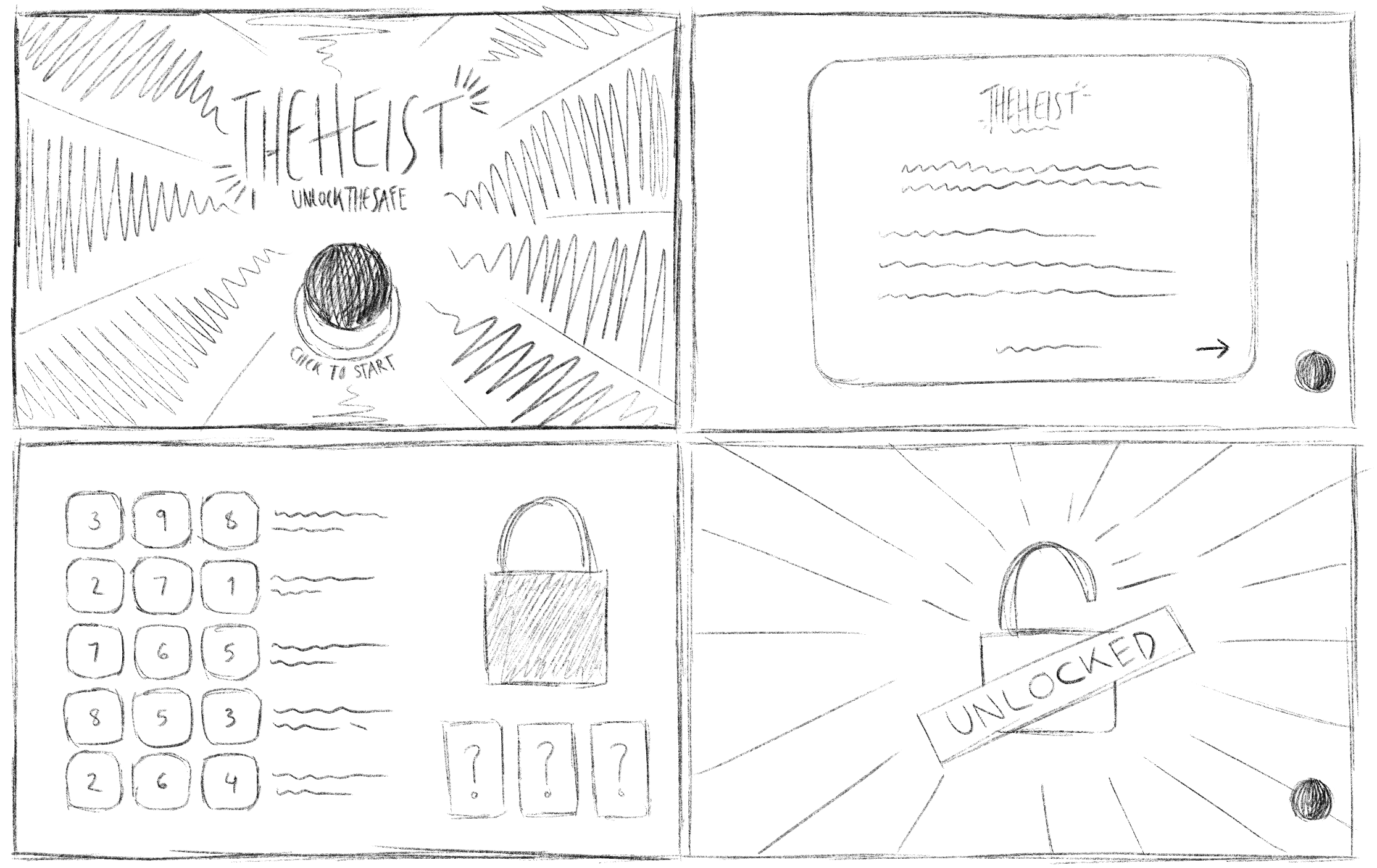
In “The Heist,” players will be on a mission to crack a safe. Initially, I was contemplating a game related to an escape room, but I realized I needed to scale down the idea due to time constraints. Therefore, I opted for an aspect commonly found in escape rooms: a safe. Players will need to guess the correct digits based on hints to unlock the safe. In terms of technicality, when the game begins, Arduino receives a pre-determined three digit code from p5. This code is the key to unlocking the safe. A servo motor locks the safe box…lock function will set the servo to position 0 (lock position) & update locked status to true. Whereas the unlock function will set servo to position 90 (unlock position) and update locked status to false. Players will use a potentiometer to select digits ranging from 0 to 9. After choosing each digit, they press a button to confirm their selection. Further, the safe design will resemble a classic bank safe.
Arduino Program Description
1. Initializing Pins & Variables
– Assign pins for the servo, two buttons, and potentiometer. Specify the potentiometer’s pin and initialize its value, along with a boolean variable set to true and a digit variable to store potentiometer readings.
– Initialize the servo motor.
2. Loop Function
– Check conditions to determine whether to call the unlock or lock function.
– Read the state of the buttons and store it in a variable.
– Read the potentiometer’s value and map it to a digit between 0 and 9.
– Print the digit, button states (true/false), and the locked status (true/false) to the Serial Monitor.
3. Lock Function
– Set the servo to position 0 (locked position).
– Update the locked status to true.
4. Unlock Function
– Set the servo to position 90 (unlocked position).
– Update the locked status to false.
The essay, or more accurately a “rant” as described by Bret Victor, mainly focuses on user interaction both presently and in the distant future. Victor argues that the sense of touch, essential to human work for millions of years, is important to understanding his argument. He emphasizes that technology doesn’t simply happen but is rather a result of careful development. In introducing the concept of “Pictures Under Glass,” which represents “an interaction paradigm of permanent numbness,” the author highlights how this denies our hands their natural capabilities. Consequently, he argues against accepting an Interface Of The Future that is less expressive than a when making a sandwich. To avoid that, Victor highlights how we must understand that the future hinges on our choices as people determine which ideas to pursue, which research to support, and how they’ll shape their professional paths. Last but not least, he wraps up with an interesting question: in a world where we control our entire bodies, should our interactions boil down to just a finger?
I understand where the author is coming from; revolutionary technology comes out of long research, but as we can see nowadays, technology is all around us, and what the author seems to be leaning toward is making technology a part of us. Don’t get me wrong, I support technology being improved & people being innovative, but I must fear that there will come a day when the line will be crossed and it will not simply be “pictures under glass,” but rather “pictures under skin.” For better or for worse, this is one of my concerns, and I believe it is a concern shared by many, which is why we have remained in an era where interactions have “permanent numbness.”The “glass” referred to in “pictures under glass” should always be there; it is when that barrier is broken that ideas will have no limit, which is a good thing, but it is also when many other things will have no limit, and that’s what’s dangerous. That said, I believe the future shouldn’t be limited to just a single finger, but also not utilized by all of them.
I have two potential project ideas/prompts: Plan A involves designing a game that revolves around unlocking a safe. In this game, players will be tasked with guessing the correct digits of a passcode to unlock the safe. The passcode will be generated randomly at the start of the game and transmitted to an Arduino, which will control a servo motor to lock the safe box. Players can input their guesses using either buttons or potentiometers (either limit the digits to 1-5 and use five buttons OR use the potentiometer to choose the digits from 0-9 and press a button to enter OR use four potentiometers for each digit without a button to enter), depending on the chosen design. The safe itself could be modeled after a traditional bank safe or a more modern safe box.
Alternatively (if plan a didn’t work out), Plan B would involve expanding upon my midterm project, which included the Elevator Rush game. This game was inspired by the frustration of waiting for elevators during busy times, such as the rush between classes. Players control an elevator, picking up students to ensure they reach class on time. I’m considering bringing this game to life by creating a physical model of the elevator/C2 space, which would allow users to interact with it physically.
For this final project, I envisioned entering a universe where art and technology collide to create something genuinely unique. I wanted to make it easy for people who have never drawn before to experience it for the first time.
Imagine an interactive space where art and technology merge, transforming bodily movements into a rainbow of colours on a digital canvas. My initiative encourages individuals to exhibit their ideas through motion. They use a paintbrush attached to an Arduino to navigate a symphony of colourful ellipses. This is more than simply an artwork; it’s an experience that captures the essence of movement and transforms it into a personalised digital masterpiece.
Arduino Part:
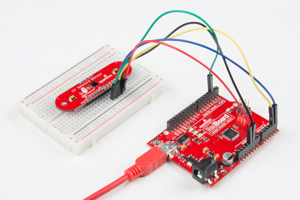
The foundation of the interaction is the Arduino Uno, on which I worked with a ZX Distance and Gesture Sensor. The sensor is adept at monitoring the paintbrush’s proximity as well as the artist’s minor hand gestures. To be honest, installation was rather simple, but the sensor itself was not as powerful as planned.
Input: Proximity data and gesture commands from the ZX Sensor. Output: Serial communication to relay the sensor data to the computer running the p5.js sketch. Data to p5.js: Real-time Z-axis data for proximity (distance of the hand or brush from the sensor) and X-axis data for lateral movement, along with gesture detections (swipes, taps). From p5.js: Instructions may be sent back to calibrate gesture sensitivity or toggle the sensor’s active state.
P5.js Part:
On the digital front, p5.js will serve as the canvas and palette, with dynamic and malleable capabilities. It will translate the incoming data from the Arduino into a series of colours and movements on the screen.
Receiving Data: Interpreting proximity and gesture data from the Arduino.
Processing Movements: Real-time mapping of hand movements to colour strokes and splashes with varied intensity and spread on a digital canvas. Visual Feedback: Dynamic visual changes that reflect the flow and dance of the user’s motions. To Arduino: Signals for modifying the ZX Sensor parameters in response to real-time performance and user feedback.
Graphics Used:
Gesture: Swipe Left / Right, Tap
Visuals: Dynamic shapes, colors, and brush strokes based on movement data.
Development and User Testing
The ZX Distance and Gesture Sensor has now been integrated with Arduino, and the immediate goal is to ensure that data flows smoothly into the p5.js programme. By the time user testing begins next week, the system should respond to hand motions by presenting relevant visual modifications on the screen.
User Testing Objectives:
Assess how natural and fulfilling it is to paint in midair.
Ensure responsiveness and accuracy of gesture detection.
Gather feedback from participants regarding the ease of use and satisfaction with the interactive art experience.
User Testing Techniques:
Record interactions on video to analyze gesture accuracy and timing.
How it Works:
Arduino Setup: Connect Arduino to the ZX Sensor and establish serial communication with p5.js.
Gesture Detection: The Arduino reads gestures and proximity data and sends this information to the p5.js sketch.
Canvas Response: p5.js interprets the data and creates a dynamic visual display that reflects the gestures and brush movements.
Feedback Loop: p5.js sends calibration data back to Arduino to adjust the sensor settings if necessary.
Code Arduino Code Example:
#include <Wire.h>
#include <ZX_Sensor.h>

// Constants
const int ZX_ADDR = 0x10;  // ZX Sensor I2C address

// Global Variables
ZX_Sensor zx_sensor = ZX_Sensor(ZX_ADDR);
uint8_t x_pos;
uint8_t z_pos;
uint8_t handPresent = false;

void setup() {

  Serial.begin(9600);

  zx_sensor.init();


   while (Serial.available() <= 0) {

    Serial.println("0,0,0"); // send a starting message

    delay(50);
  }
}

void loop() {

  // If there is position data available, read and print it
  if ( zx_sensor.positionAvailable() ) {
    uint8_t x = zx_sensor.readX();
    if ( x != ZX_ERROR ) {
      x_pos=x;
    }
    uint8_t z = zx_sensor.readZ();
    if ( z != ZX_ERROR ) {
      z_pos=z;
    }
    handPresent=true;
  } else {
    handPresent=false;
  }

   while (Serial.available()) {


    int  inbyte = Serial.parseInt();
    if (Serial.read() == '\n') {

      Serial.print(x_pos);
      Serial.print(',');
      Serial.print(z_pos);
      Serial.print(',');
      Serial.println(handPresent);
    }
  }

}
P5 Code:
// FINAL PROJECT BY STEFANIA PETRE
// FOR INTRO TO IM

let img;
let brushSize = 19;
let colorHue = 0;
let previousX = 0,
  previousY = 0;
let xPos = 0;
let zPos = 0;
let smoothedX = 0;
let handPresent = 0;
let showDrawing = false;
let startButton;
let mappedX = 0;
let mappedZ = 0;

function preload() {
  img = loadImage("start.webp");
}

function setup() {
  createCanvas(640, 480);
  colorMode(HSB, 360, 100, 100, 100);
  textSize(18);

  // Set up the start button
  startButton = createButton("Get Creative!");
  startButton.position(290, 175);
  startButton.mousePressed(startDrawing);


  let fullscreenButton = createButton("Fullscreen");
  fullscreenButton.position(10, 10);
  fullscreenButton.mousePressed(toggleFullScreen);

  // Set the initial hue
  colorHue = random(360);
}

function draw() {
  if (!showDrawing) {
    background(img);
  } else {
    if (!serialActive) {
      background(0);
      fill(255);
      //text("Press the 'Get Creative!' button to start drawing", 20, 30);
    } else {
      if (handPresent == 1) {
        // Adjust mapping ranges according to your actual data
        mappedX = map(xPos, 180, 40, 0, width);
        mappedZ = map(zPos, 240, 25, 0, height);

        mappedX = constrain(mappedX, 0, width);
        mappedZ = constrain(mappedZ, 0, height);

        let weight = 10; // Adjust as needed
        let strokeColor = color(colorHue % 360, 100, 100);

        stroke(strokeColor);
        strokeWeight(weight);
        ellipse(mappedX, mappedZ, weight * 2, weight * 2);

        previousX = mappedX;
        previousY = mappedZ;
      }

      colorHue += 2;

      noStroke();
      fill(0, 0, 0.000000000000005, 1);
      rect(0, 0, width, height);
    }
  }
}

function startDrawing() {
  showDrawing = true;
  startButton.hide();
  setUpSerial();
}

function toggleFullScreen() {
  let fs = fullscreen();
  fullscreen(!fs);
  resizeCanvas(windowWidth, windowHeight);
  startButton.position(windowWidth / 2 - 40, windowHeight / 2 - 30);
}

function readSerial(data) {
  if (data != null) {
    let fromArduino = split(trim(data), ",");
    if (fromArduino.length == 3) {
      xPos = int(fromArduino[0]);
      zPos = int(fromArduino[1]);
      handPresent = int(fromArduino[2]);
    }
    let sendToArduino = 0 + "\n";
    writeSerial(sendToArduino);
  }
}

function keyPressed() {
  if (key == " ") {
    setUpSerial();
  }
}

function windowResized() {
  resizeCanvas(windowWidth, windowHeight);
}
Final thoughts:
Even though the project was not exactly how I have pictured it at the beginning, it still worked out well. People at the showcase liked it and everything worked for 3 hours and I am happy that I have chosen this path.
The concept of this project revolves around creating an interactive UFO game titled “UFO Escape.” The main goal is to score points by avoiding collisions with asteroids and navigating through space. What sets this game apart is its unique control scheme: players use a glove equipped with a gyroscope sensor as the game controller. This setup allows the game to translate the player’s hand tilt movements into navigational commands within the game environment to turn the UFO in different directions.
Final Concept of the project:
Video of interaction:
Description of interaction design
Implementing the “UFO Escape” game involves an interaction design that merges physical computing with digital interfaces to create an immersive gaming experience. Here’s a detailed breakdown of the interaction design and implementation:
Hardware Setup:
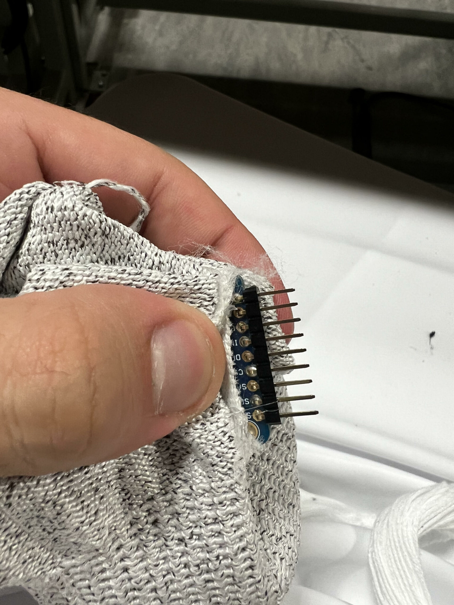
Gyroscope Sensor (3-Axis Gyroscope L3GD20H):
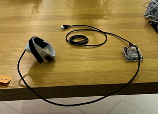
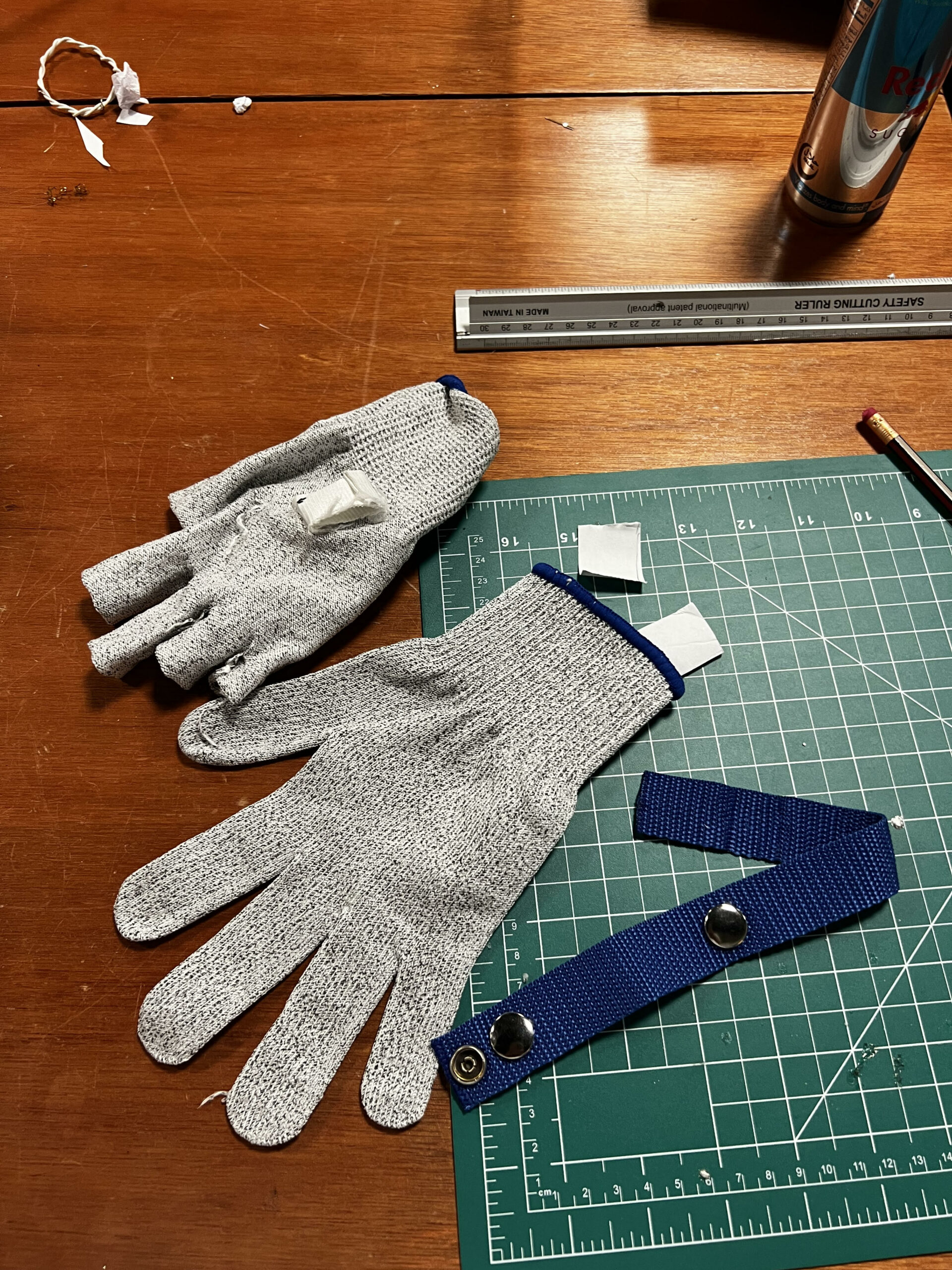
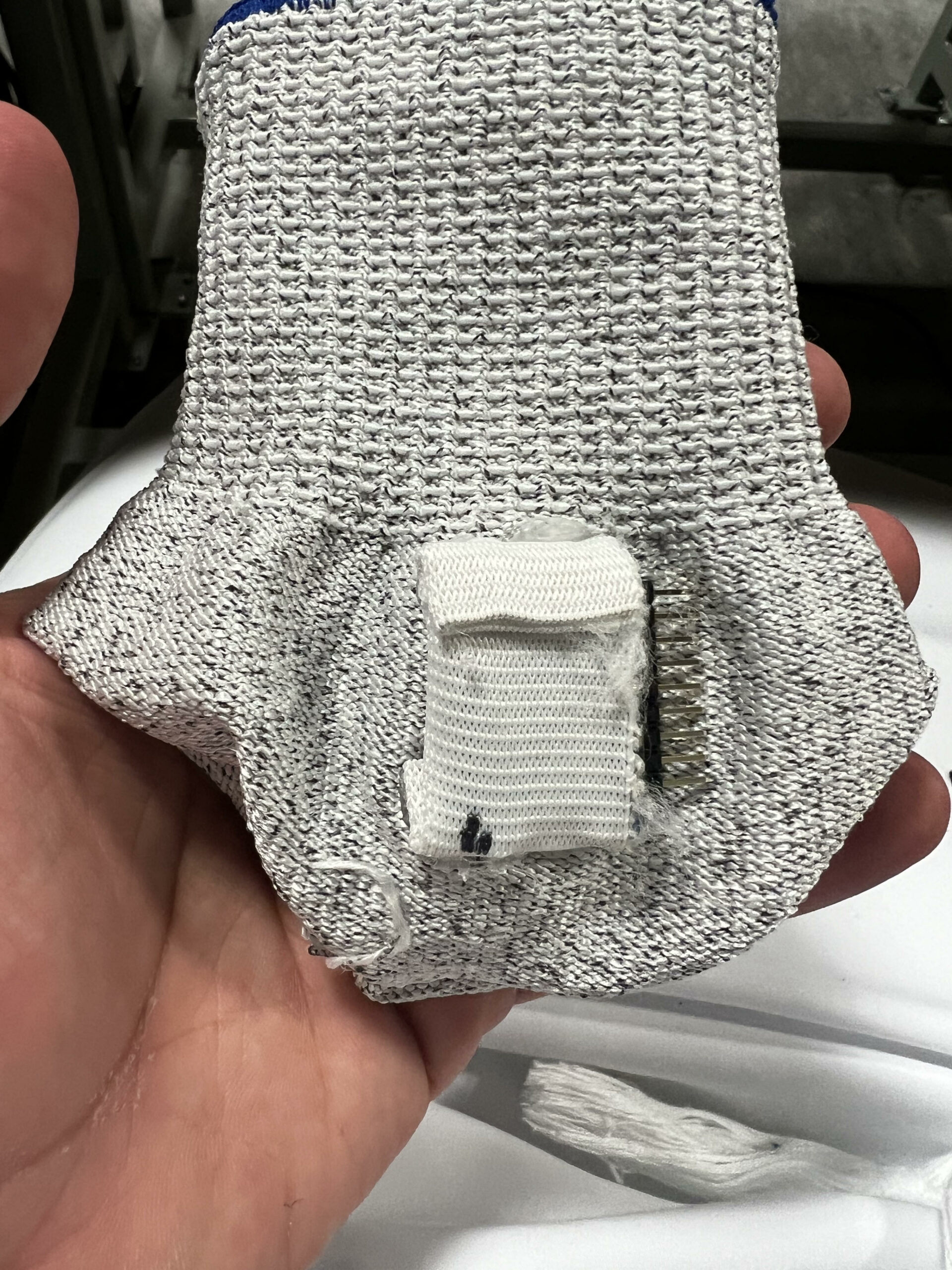
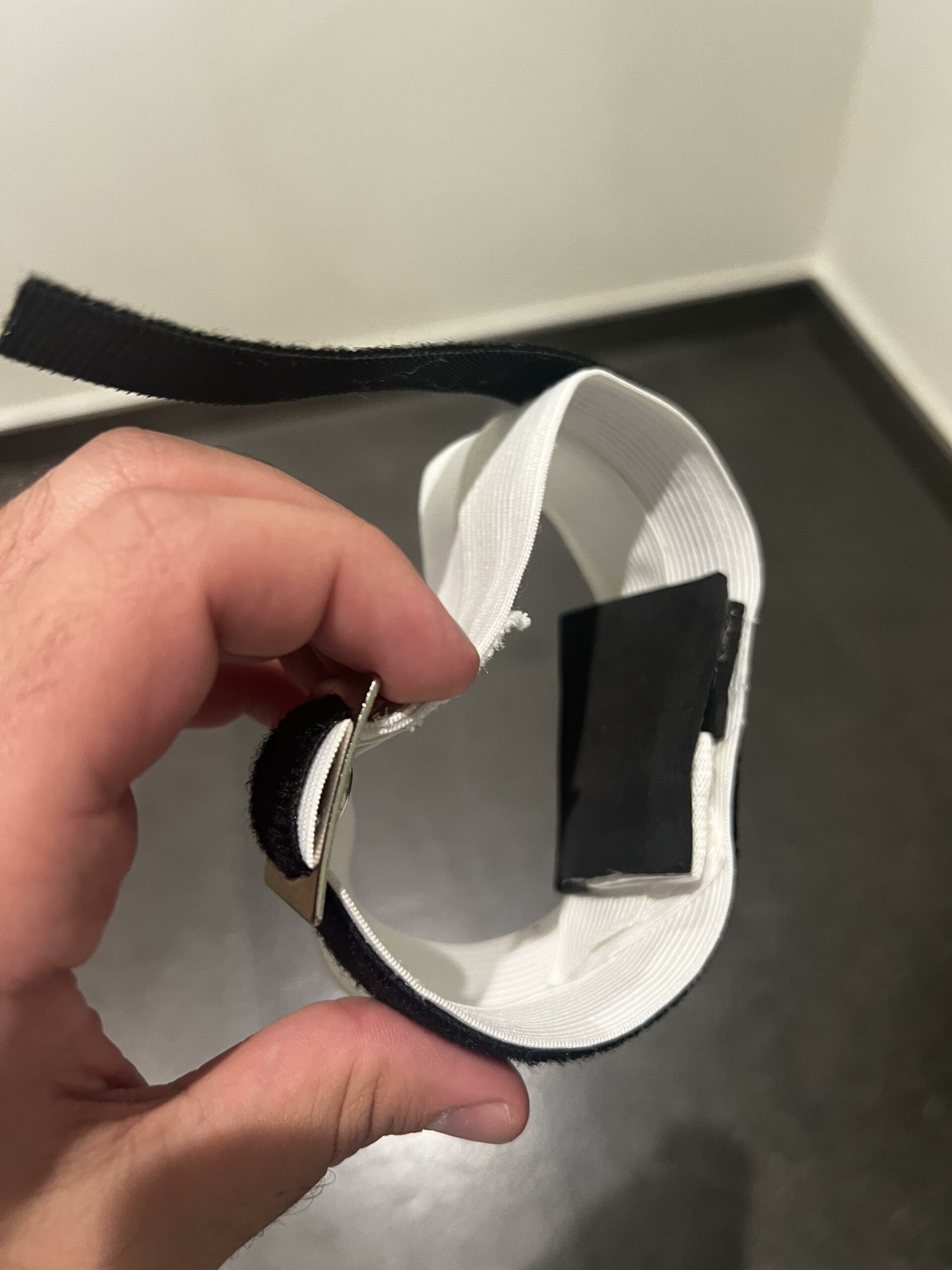
This sensor is integrated into a wearable glove made from velcro, foam tape, and cloth. The glove is then connected to an Arduino UNO using 4 jumper wires soldered to a 90-cm length. It is then covered by heat-shrinkable rubber tubing for aesthetics and a better wire management setup.
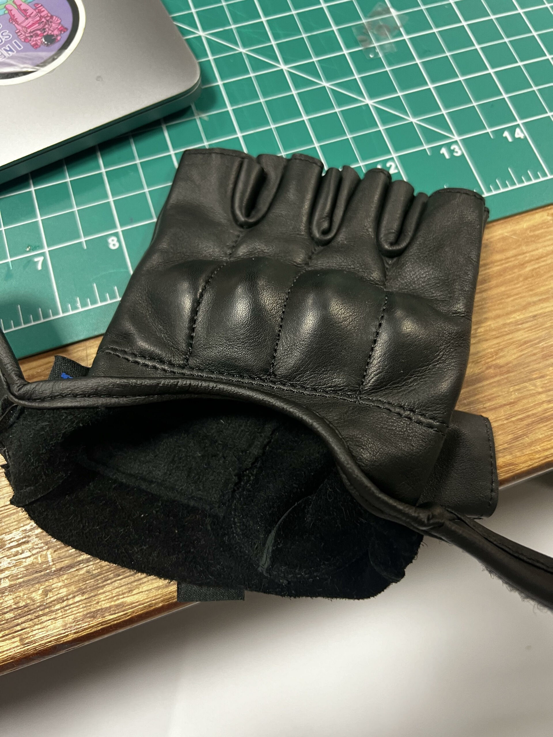
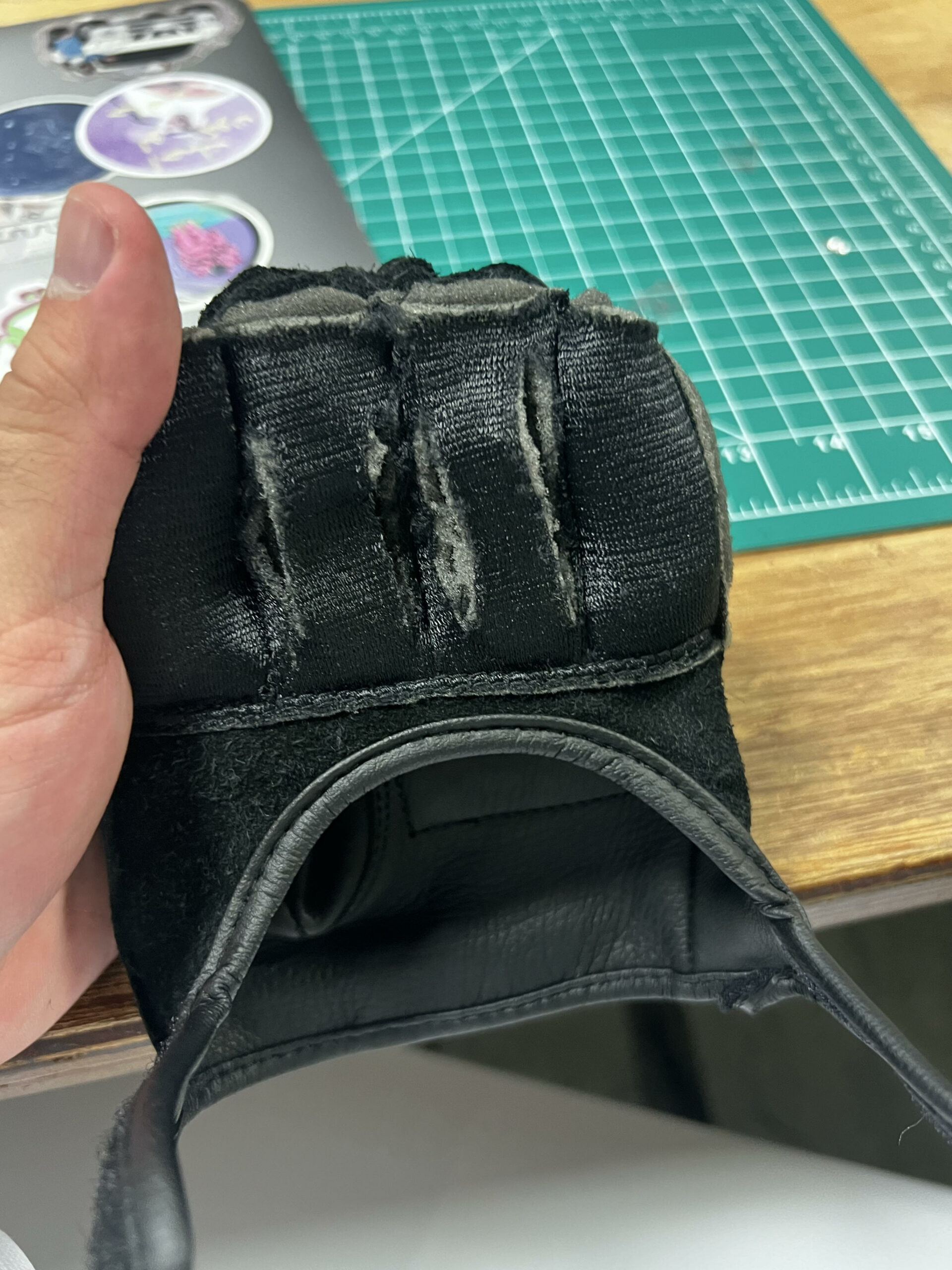
I kept changing the glove’s prototypes due to either wiring issues or the fact that none were non-adjustable. Below are the different versions of the glove.
First Prototype:
This version did not allow the cables to function properly due to the positioning of the gyroscope.
Second Prototype:
This glove secured the gyroscope, but due to it not being adjustable, it kept causing issues with the wires whenever a different sized hand would wear it.
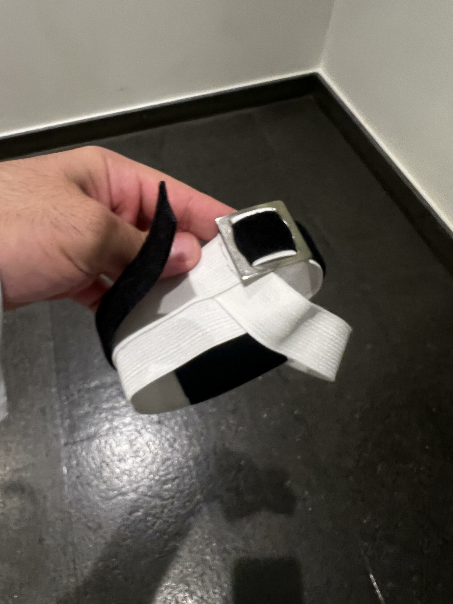
Final Prototype:
This glove concept fixed all the issues mentioned previously, from sizing difficulties to wire management, making it the ideal version for various hand sizes. It was made from scratch in the IM lab using different materials to secure the glove and a metal piece to lock in the velcro I got from home from a metal glove.
Cabling:
The cable was soldered on a stranded wire to extend the jumper wires for a more usable length for the glove.
How the code works:
The gyroscope sensor extracts the X and Y variables read by the Arduino to determine the hand’s position and movement. The Arduino Uno sends those as instructions for where the UFO should be positioned, which the P5 file reads and translates.
// Function to move the player based on arrow key inputs
  move() {
    let moveSpeed = 10; // Speed multiplier
    this.gotoX += gyroData.x * moveSpeed;
    this.gotoY += gyroData.y * moveSpeed;

    this.gotoX = constrain(this.gotoX, 30, width - 30);
    this.gotoY = constrain(this.gotoY, 30, height - 30);

    this.x = lerp(this.x, this.gotoX, 0.1);
    this.y = lerp(this.y, this.gotoY, 0.1);

    if (frameCount % 100 === 0) {
      obstacles.push(new Obstacle()); // Add new obstacles
    }

    this.gotoX = constrain(this.gotoX, 30, width - 30); // Keeps player within horizontal bounds
    this.gotoY = constrain(this.gotoY, 30, height - 30); // Keep player within vertical bounds
    // //This is only so the player cannot exist the canvas
  }
This processes the gyroscope data to interpret the player’s hand movements as specific commands (left, right, up, down, accelerate).
Serial Communication:
The Arduino transmits the processed data to a computer via serial communication, and in my case, it provided the P5 with the full library of serial communication, which made the process work for me.
/**
 * p5.webserial
 * (c) Gottfried Haider 2021-2023
 * LGPL
 * https://github.com/gohai/p5.webserial
 * Based on documentation: https://web.dev/serial/
 */

'use strict';
Game Mechanics:
The game is developed in a way that makes it hard for the player to achieve a high score by making the meteorites come down faster and faster as the player progresses to higher scores.
// Function to update obstacle position
  update() {
    this.y += map(score, 0, 10, gameSpeed, gameSpeed + 5); // Moves obstacles down the screen
    //this will make game harder as time grows
  }
}
Also, the player should be included in the provided map of the game so no cheating occurs and the game is played fairly based on skill levels.
this.gotoX = constrain(this.gotoX, 30, width - 30); // Keeps player within horizontal bounds this.gotoY = constrain(this.gotoY, 30, height - 30); // Keep player within vertical bounds // //This is only so the player cannot exist the canvas }
Player Interaction:
Players wear the gyroscope-equipped glove and move their hands to control the UFO within the game. Movements are intuitive: tilting the hand to the sides steers the UFO laterally, while tilting forward or backward would control vertical movement, and depending on how fast you tilt your hands, you could possibly send the UFO in any direction of the map faster than needed making you very aware of what move you would wanna make next as the meteoroids are coming down.
Visuals/Audio:
The game provides real-time visual feedback by updating the position and movements of the UFO based on the player’s actions as well as background noise for when the UFO is flying around.
P5 Sketch:
let port; // Serial port instance
let gyroData = { x: 0, y: 0 }; // Placeholder for gyro data
let serialInterval; // Interval for polling serial data

// Variables for game assets
let bgImage; // Variable to hold the background image for menu and game over screens
let bgMusic; // Variable to hold the background music for gameplay
let player; // Player object
let obstacles = []; // Array to store obstacles
let gameSpeed = 6; // Speed at which obstacles move
let score = 0; // Player's score
let gameState = "MENU"; // Initial game state; that is "MENU", "PLAYING", or "GAME OVER"
let rockImage; // Variable to hold the rock image
let gameOverImage;


// Preload function to load game assets before the game starts
function preload() {
  // bgImage = loadImage("space.png"); // Loads the background image
  menuImage = loadImage("menu.jpeg");
  // gameplayBgImage = loadImage("gameplay.jpg"); // Loads the gameplay background image
  bgMusic = loadSound("gameplaysound.mp3"); // Loads the background music
  rockImage = loadImage("rock-2.png"); // Loads the rock image
}

// The setup function to initialize the game
function setup() {
  createCanvas(750, 775).parent("canavs-container"); // Size of the game canvas
  openButton = createButton("Connect Arduino")
    .position(410, 20)
    .style("background-color", "rgba(244,238,238,0.1)(255, 50)")
    .style("border-radius", "70px")
    .style("padding", "10px 20px")
    .style("font-size", "15px")
    .style("color", "white")
    .mousePressed(openSerialPort); // Click to open serial port
  player = new Player(); // Initializes the player object
  textAlign(CENTER, CENTER); // Setting text alignment for drawing text
  textFont("arial");
}

function openSerialPort() {
  port = createSerial(); // Initialize the serial port instance
  if (port && typeof port.open === "function") {
    port.open("Arduino", 9600); // Open with a predefined preset
    // Set up polling to check for serial data every 100ms
    serialInterval = setInterval(readSerialData, 100); // Poll for data
  } else {
    console.error("Failed to initialize the serial port.");
  }
}

function readSerialData() {
  if (port && port.available()) {
    let rawData = port.readUntil("\n"); // Reads data till newline
    if (rawData && rawData.length > 0) {
      let values = rawData.split(","); // Splits by commas
      if (values.length === 2) {
        gyroData.x = parseFloat(values[0]); // Parse X value
        gyroData.y = parseFloat(values[1]); // Parse Y value
      } else {
        console.error("Unexpected data format:", rawData); // Error handling
      }
    }
  }
}

// Draw function called repeatedly to render the game
function draw() {
  // Displays the space background image only during menu and game over states but displays a different image during gameplay
  if (gameState === "PLAYING") {
    background("#060C15");
    noStroke();
    fill(255);
    for (let star of stars) {
      circle(star.x, star.y, star.r);
      star.y += star.yv;
      if (star.y > height + 5) star.y = -5;
    }
  }

  // Handles game state transitions
  if (gameState === "MENU") {
    drawMenu();
  } else if (gameState === "PLAYING") {
    if (!bgMusic.isPlaying()) {
      bgMusic.loop(); // Looping the background music during gameplay
    }
    playGame();
  } else if (gameState === "GAME OVER") {
    bgMusic.stop(); // Stops the music on game over
    drawGameOver();
  } else {
    //info
    drawInfo();
  }
}

function drawInfo() {
  background("#060C15");
  noStroke();
  fill(255);
  for (let star of stars) {
    circle(star.x, star.y, star.r);
    star.y += star.yv;
    if (star.y > height + 5) star.y = -5;
  }
  textSize(16);
  text(
    "Connect the Arduino\n Wear the glove\n, Control the UFO through tilting your hand \nLeft, Right, Up and Down.",
    width / 2,
    height / 2
  );
  stroke(255);
  Button("MENU", width / 2, height - 100, 100, 40);
}

// ---------------Function to display the game menu
function drawMenu() {
  background(menuImage);
  fill(200, 100, 100);
  stroke(200, 100, 100);
  textSize(62);
  strokeWeight(2);
  text("UFO ESCAPE", width / 2, 140);
  fill(255);
  text(
    "UFO ESCAPE",
    width / 2 - map(mouseX, 0, width, -5, 5),
    135 - map(mouseY, 0, height, -2, 2)
  );
  let x, y;
  if (frameCount % 40 < 20) {
    x = width / 2 - map(frameCount % 40, 0, 20, -5, 5);
    y = 400;
  } else {
    x = width / 2 - map(frameCount % 40, 20, 40, 5, -5);
    y = 400;
  }
  Ufo(x, y, 60, 30);
  //startButton
  Button("START", width / 2, 550);
  //info page
  Button("INFO", width - 115, 40, 100, 40);
}

// Function to handle gameplay logic
function playGame() {
  fill(255);
  textSize(25);
  text(`Score: ${score}`, width / 2, 50);

  player.show(); // Displays the player
  player.move(); // Moves the player based on key inputs

  // Adding a new obstacle at intervals
  if (frameCount % 120 == 0) {
    obstacles.push(new Obstacle());
  }

  // Updates and displays obstacles
  for (let i = obstacles.length - 1; i >= 0; i--) {
    obstacles[i].show();
    obstacles[i].update();
    // Checks for collisions
    if (player.collidesWith(obstacles[i])) {
      gameOverImage = get();
      gameState = "GAME OVER";
    }
    // Removes obstacles that have moved off the screen and increment score
    if (obstacles[i].y > height) {
      obstacles.splice(i, 1);
      i--;
      score++;
    }
  }
}

// Function to display the game over screen
function drawGameOver() {
  if (gameOverImage) image(gameOverImage, 0, 0);
  fill(200, 100, 100);
  stroke(200, 100, 100);
  textSize(46);
  text("GAME OVER", width / 2, height / 2 + 50);
  fill(255);
  text(score, width / 2, height / 2 - 50);

  Button("RESTART", width / 2, 550);
}

// Function to reset the game to its initial state
function resetGame() {
  obstacles = []; // Clear existing obstacles
  score = 0; // Reset score
  player = new Player(); // Reinitialize the player
  stars = [];
  for (let i = 0; i < 100; i++) {
    let r = random(1, 3);
    stars.push({
      x: random(width),
      y: random(height),
      r: r,
      yv: map(r, 1, 3, 0.01, 0.1),
    });
  }
}

// Player class
class Player {
  constructor() {
    this.width = 60; // Width of the UFO
    this.height = 30; // Height of the UFO
    this.x = width / 2; // Starting x position
    this.y = height - 100; // Starting y position
    this.gotoX = this.x;
    this.gotoY = this.y;
    this.speed = 5;
  }

  // Function to display the UFO
  show() {
    this.y = lerp(this.y, this.gotoY, 0.1);
    this.x = lerp(this.x, this.gotoX, 0.1); //and change this.gotoX
    stroke(200, 100, 100);

    Ufo(this.x, this.y, this.width, this.height);
  }

  // Function to move the player based on arrow key inputs
  move() {
    let moveSpeed = 10; // Speed multiplier
    this.gotoX += gyroData.x * moveSpeed;
    this.gotoY += gyroData.y * moveSpeed;

    this.gotoX = constrain(this.gotoX, 30, width - 30);
    this.gotoY = constrain(this.gotoY, 30, height - 30);

    this.x = lerp(this.x, this.gotoX, 0.1);
    this.y = lerp(this.y, this.gotoY, 0.1);

    if (frameCount % 100 === 0) {
      obstacles.push(new Obstacle()); // Add new obstacles
    }

    this.gotoX = constrain(this.gotoX, 30, width - 30); // Keeps player within horizontal bounds
    this.gotoY = constrain(this.gotoY, 30, height - 30); // Keep player within vertical bounds
    // //This is only so the player cannot exist the canvas
  }

  // Function to detect collision with obstacles
  collidesWith(obstacle) {
    return (
      dist(
        obstacle.x + obstacle.radius,
        obstacle.y + obstacle.radius,
        this.x,
        this.y
      ) < 45
    );
  }
}

// Obstacle class
class Obstacle {
  constructor() {
    this.radius = random(15, 30); // Random radius for obstacle
    this.x = random(this.radius, width - this.radius); // Random x position
    this.y = -this.radius; // Starts off-screen so it looks like its coming towards you
  }

  // Function to display the rocks
  show() {
    image(rockImage, this.x, this.y, this.radius * 2, this.radius * 2); // Draws them as a circle
  }

  // Function to update obstacle position
  update() {
    this.y += map(score, 0, 10, gameSpeed, gameSpeed + 5); // Moves obstacles down the screen
    //this will make game harder as time grows
  }
}
function Button(txt, x, y, w = 200, h = 60) {
  fill(255, 50);
  if (
    mouseX > x - w / 2 &&
    mouseX < x + w / 2 &&
    mouseY > y - h / 2 &&
    mouseY < y + h / 2
  ) {
    fill(255, 80);
    if (mouseIsPressed) {
      mouseIsPressed = false; //so only one click happnes
      action(txt);
    }
  }
  rect(x, y, w, h, h / 2);
  fill(255);
  textSize(h / 2);
  text(txt, x, y);
}
function action(txt) {
  switch (txt) {
    case "START":
      gameState = "PLAYING";
      resetGame();
      break;
    case "RESTART":
      gameState = "MENU";
      resetGame();
      break;
    case "INFO":
      stars = [];
      for (let i = 0; i < 100; i++) {
        let r = random(1, 3);
        stars.push({
          x: random(width),
          y: random(height),
          r: r,
          yv: map(r, 1, 3, 0.01, 0.1),
        });
      }
      gameState = "INFO";
      break;
    case "MENU":
      gameState = "MENU";
      break;
  }
}

function Ufo(x, y, w, h) {
  fill(255); // Sets color to white
  rectMode(CENTER);
  rect(x, y, w, h, 20); // Draws the UFO's body
  fill(20); // Sets the glass color to red
  arc(x, y - h / 4, w / 2, h / 1, PI, 0, CHORD); // Draws the glass
  stroke(255);
  let a = map(x, 0, width, 0, PI / 4);

  arc(x, y - h / 4, w / 2 - 5, h - 5, -PI / 4 - a, -PI / 6 - a);

  for (let i = 1 + frameCount; i < 10 + frameCount; i++) {
    let x_ = map(i % 10, -1, 10, -30, 30);
    circle(x + x_, y, 5);
  }
}
Arduino Code:
#include <Wire.h>
#include <Adafruit_L3GD20_U.h>

// Initialize the L3GD20 object
Adafruit_L3GD20_Unified gyro = Adafruit_L3GD20_Unified(20); // Sensor ID

void setup() {
  Serial.begin(9600); // Start serial communication at 9600 baud

  // Initialize the L3GD20 gyroscope
  if (!gyro.begin()) {
    Serial.println("Failed to find L3GD20 gyroscope");
    while (1) {
      delay(10); // Halt if initialization fails
    }
  }
}

void loop() {
  sensors_event_t event;
  gyro.getEvent(&event);

  // Send the X and Y gyro data with a newline at the end
  Serial.print(event.gyro.x, 4); // X-axis gyro data with 4 decimal places
  Serial.print(","); // Comma separator
  Serial.println(event.gyro.y, 4); // Y-axis gyro data with 4 decimal places

  delay(100); // Adjust delay as needed
}
What are some aspects of the project that you’re particularly proud of?
To be honest, the whole final project makes me proud that I was able to create such a complicated code with actual use in the end. The glove prototypes are also something that I was proud of because I have never created a glove from scratch before. I am just glad that it all worked out in the end and that the cables stopped popping out of the gloves whenever someone would put them on.
What are some areas for future improvement?
I would say that expanding on the game itself and making different levels and maps for the UFO to fly around in would also exemplify the game. Also, creating a button in the glove to restart once you press it would make it easier for the player to control the whole game if they lose.
My game concept simulates driving safely through a hailstorm in AbuDhabi. As a player, you control a toy car, displayed on the screen, by physically moving it left or right to dodge falling hailstones. This game is designed to reflect the unpredictable nature of real hailstorms and incorporates real-time physical interaction through a toy car and Arduino sensors, offering a unique and engaging gameplay experience, also symbolizing the hailstorm in Abu Dhabi months ago.
Implementation Overview
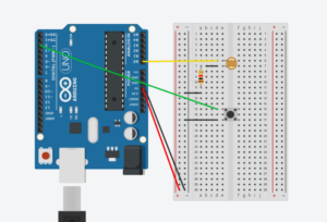
I built the game using p5.js for the visual components and game logic, and Arduino for the physical interaction aspects. The Arduino setup uses a pushbutton to start or restart the game and an HC-SRO ultrasonic sensor to determine the position of the toy car, which translates into the car’s movement on the screen. These inputs are sent to the p5.js application through serial communication, allowing the player’s physical movements to directly influence the gameplay.
Interaction Design Description
The interaction design focuses on tangible interaction, where the physical movement of the toy car (left or right) translates to the movement of the car on the screen. This method fosters more engaging and intuitive gameplay. An arcade button connected to the Arduino allows players to start or restart the game easily, making the interface user-friendly and accessible.
Arduino Code Explanation
In my Arduino code, I manage inputs from the ultrasonic sensor and the button. The ultrasonic sensor measures the distance of an object (the toy car) from the sensor, and this measurement is used to control the car’s position on the p5.js screen. The button input is debounced to avoid processing multiple unintended signals, used to start or restart the game, and toggles an LED for visual feedback. Serial communication sends the button press count and distance measurement to the p5.js application.
p5.js Code Explanation
My p5.js code is responsible for creating the visual representation of the game—rendering the car, hailstones, and other visual elements on the screen. It also handles the game logic, such as detecting collisions between the car and hailstones, updating the game state based on Arduino inputs, and managing game timers and scores.
The game has 3 screens:
The Main menu where the player is told the directions to play, the winning screen which comes up after 10 seconds of the user playing, and the game over screen which pops up if the car collides with the hailstones.
Communication Between Arduino and p5.js
I achieve communication between the Arduino and p5.js through serial communication. The Arduino continuously sends data from the button and the ultrasonic sensor to the p5.js application, which reads this data to update the game state accordingly. The p5.js listens for serial data, parses it, and uses these inputs to control the car’s movements and manage game controls like start and restart.
Important Images
Aspects I’m Particularly Proud Of
I am proud of several key accomplishments in this project:
Successfully integrating physical components with a digital interface, which enhanced the interactive gaming experience.
Overcoming the challenges associated with serial communication between Arduino and p5.js, a complex aspect of hardware-software integration.
Completing the project within a limited timeframe and being able to innovate with a unique approach to game design and interaction.
As well as my setup with the street and box; I really enjoyed making the box and the street, adding an extra layer of creativity
Future Improvement Areas
For future enhancements, I could consider:
Implementing sound and music for the game, I initially had music in the game but I decided to remove it, since the exhibition is already quite chaotic and the music won’t be heard
Enhancing the game’s visual and sound effects to create a more immersive experience.
Implementing additional gameplay features, such as different levels of difficulty or various weather conditions affecting gameplay.
Exploring different sensors or refining the calibration of the HC-SRO4 sensor. As it was slightly glitchy at first, but I managed to fix it.
Here is my Arduino code:
const int trigPin = 9;
const int echoPin = 10;

// Arduino code for button, which detects the counts
const int buttonPin = 2;  // the number of the pushbutton pin
const int ledPin = 3;    // the number of the LED pin

// variables will change:
int buttonState = 0;         // variable for reading the pushbutton status
int lastButtonState = HIGH;  // variable for reading the last pushbutton status
unsigned long lastDebounceTime = 0;  // the last time the output pin was toggled
unsigned long debounceDelay = 50;    // the debounce time; increase if the output flickers
int pressCount = 0;  // count of button presses


void setup() {
  pinMode(trigPin, OUTPUT);
  pinMode(echoPin, INPUT);
   pinMode(ledPin, OUTPUT);   // initialize the LED pin as an output
  pinMode(buttonPin, INPUT_PULLUP);  // initialize the pushbutton pin as an input with internal pull-up resistor
  Serial.begin(9600);
}

void loop() {
  float distance = getDistanceCm();  // Get the distance in cm
  int reading = digitalRead(buttonPin);

  // check if the button state has changed from the last reading
  if (reading != lastButtonState) {
    // reset the debouncing timer
    lastDebounceTime = millis();
  }

  if ((millis() - lastDebounceTime) > debounceDelay) {
    // if the button state has changed:
    if (reading != buttonState) {
      buttonState = reading;

      // only toggle the LED if the new button state is LOW
      if (buttonState == LOW) {
        digitalWrite(ledPin, HIGH);
        pressCount++;  // increment the press count
      } else {
        digitalWrite(ledPin, LOW);
      }
    }
  }

  // save the reading. Next time through the loop, it will be the lastButtonState:
  lastButtonState = reading;

  Serial.print(pressCount);  // print the count to the serial monitor
  Serial.print(",");
  Serial.println(distance);          // Print the distance to the Serial monitor
  delay(100);                        // Short delay before next measurement
}

float getDistanceCm() {
  // Trigger the measurement
  digitalWrite(trigPin, LOW);
  delayMicroseconds(2);
  digitalWrite(trigPin, HIGH);
  delayMicroseconds(10);
  digitalWrite(trigPin, LOW);

  // Calculate the distance based on the time of echo
  float duration = pulseIn(echoPin, HIGH);
  float distance = (duration * 0.0343) / 2;

  return distance;
}
And this is the code from P5:
//Add this in index.html
//   <!-- Load the web-serial library -->
//     <script src="p5.web-serial.js"></script>

// Go download the web serial at https://github.com/Pi-31415/Intro-To-IM/blob/main/p5.web-serial.js

// Declare a variable to hold the smoothed value
let smoothedDistance = 0;
let gameMode = 0; // Variable to store the current game mode
var landscape; // Variable to store the landscape graphics
var car_diameter = 15; // Diameter of the ball
var bomb_diameter = 10; // Diameter of the bombs
var cardistancex;
var ypoint;
var zapperwidth = 6; // Width of the zapper
var numofbombs = 3; // Number of bombs
var bombposX = []; // Array to store X positions of bombs
var bombposY = []; // Array to store Y positions of bombs
var bombacceleration = []; // Array to store acceleration of each bomb
var bombvelocity = []; // Array to store velocity of each bomb
var time = 0; // Variable to track time, usage context not provided
var timeperiod = 0; // Variable to store a time period, usage not clear without further context
//var score = 0; // Variable to store the current score
var posX; // X position, usage context not provided
var inMainMenu = true; // Boolean to check if the game is in the main menu
//var prevScore = 0; // Variable to store the previous score
let font; // Variable to store font, usage context not provided
let introgif;
let gameovergif;
let gif3;
let survivedgif;
let countdownTimer = 10; // Countdown timer starting from 30 seconds
let serial; // Declare a serial port object
let latestData = "waiting for data"; // Latest data received
let gameovernow = false;

//CONNECTION

let clickCount = 0;
let previousClickCount = 0; // Store the previous click count
let distanceReal = 255;

let ignorefirstclick = false;

let gameovergifLarge;

function preload() {
  introgif = createImg(
    "https://media.giphy.com/media/v1.Y2lkPTc5MGI3NjExNTA4MG42MWlhdWV3Y2cyZ3U1cTFqZHhpbHp1amcweDhjYzhkcHBkYyZlcD12MV9pbnRlcm5hbF9naWZfYnlfaWQmY3Q9Zw/35cSlj5ELlzGSg0ZYM/giphy.gif"
  );
  introgif.hide();
  survivedgif = createImg(
    "https://media.giphy.com/media/v1.Y2lkPTc5MGI3NjExdm1yeWt3aGlteWZkcHB3czk3Ym81YWtrZTVtb29pMng2NW83bnF4bCZlcD12MV9pbnRlcm5hbF9naWZfYnlfaWQmY3Q9Zw/LY3JbLuhmjDVfCcCxh/giphy.gif"
  );
  survivedgif.hide();
  gameovergif = createImg(
    "https://media.giphy.com/media/v1.Y2lkPTc5MGI3NjExZHo1dmNrdzQ5NnYycWdvMjBqOGt1Zmg0MTdxZHQ4eHAyZGZrMDZtbCZlcD12MV9pbnRlcm5hbF9naWZfYnlfaWQmY3Q9cw/hp9wzCTbGeGfIkXE6a/giphy.gif"
  );
  gameovergif.hide();

  gameovergifLarge = createImg("https://intro-to-im.vercel.app/afra/gameoer.gif");
  gameovergifLarge.hide();
  //Temp
  gif3 = loadImage("https://intro-to-im.vercel.app/afra/bggif.gif");

  font = loadFont("fonts/Inconsolata_Condensed-Light.ttf");
  car = loadImage("car.png");
  car2 = loadImage("car2.png");
}

// Cloud class starts
class Cloud {
  constructor(x, y, speed, stepSpeed, scale) {
    this.x = x;
    this.y = y;
    this.scale = scale; // Add scale property
    this.speed = speed;
    this.stepSpeed = stepSpeed;
    this.step = 0;
    this.facingRight = false; // Initially moving to the left
    this.animationTimer = null;
  }

  move() {
    if (this.facingRight) {
      this.x += this.speed;
    }
  }

  display() {
    push();
    if (!this.facingRight) {
      scale(-this.scale, this.scale); // Apply scale with horizontal flip
      image(oneDimensionarray[this.step], -this.x, this.y);
    } else {
      scale(this.scale, this.scale); // Apply scale
      image(oneDimensionarray[this.step], this.x, this.y);
    }
    pop();
  }

  advanceStep() {
    this.step = (this.step + 1) % 8;
  }

  startAnimation() {
    this.facingRight = true;
    clearInterval(this.animationTimer);
    this.animationTimer = setInterval(() => this.advanceStep(), this.stepSpeed);
  }

  stopAnimation() {
    this.facingRight = false;
    clearInterval(this.animationTimer);
  }
}

let clouds = [];
// Cloud class ends


// Define a maximum boundary for the distance
const maxDistance = 600;  // Set this to whatever maximum value makes sense in your context

function mapDistance(distanceReal) {
  // Define the smoothing factor (alpha). Smaller values make the motion smoother but less responsive.
  const alpha = 0.2;

  // Calculate the target position without smoothing
  const targetPosition = (640 * (distanceReal - 3)) / 17;

  // Apply exponential smoothing
  smoothedDistance = alpha * targetPosition + (1 - alpha) * smoothedDistance;

  // Ensure the smoothed distance does not exceed the maximum allowed distance
  if (smoothedDistance > maxDistance) {
    smoothedDistance = maxDistance;
  }

  return smoothedDistance;
}


function setup() {
  createCanvas(640, 480);
  textAlign(CENTER);

  gif3.resize(640 * 2, 480 * 2);

  var temp00 = 0,
    temp01 = -20;

  // A while loop that increments temp01 based on temp00 until temp01 is less than the canvas height
  while (temp01 < height) {
    temp00 += 0.02; // Increment temp00 by 0.02 in each loop iteration
    temp01 += temp00; // Increment temp01 by the current value of temp00
    timeperiod++; // Increment timeperiod in each iteration
  }

  // Calculate the initial position of posX based on zapperwidth and car_diameter
  posX = zapperwidth + 0.5 * car_diameter - 2;

  // Set cardistancex and ypoint relative to the width and height of the canvas
  cardistancex = 0.7 * width; // Set cardistancex to 70% of the canvas width
  ypoint = height - 0.5 * car_diameter + 1; // Set ypoint based on the canvas height and car_diameter

  initbombpos(); // Call the initbombpos function (presumably initializes bomb positions)

  imageMode(CENTER); // Set the image mode to CENTER for drawing images centered at coordinates

  // Initialize variables for width and height based on

  // Create 3 clouds with horizontal offsets, different speeds and scales
  clouds.push(new Cloud(width / 8, height / 9, 0, 100, 0.9)); // First cloud
  clouds.push(new Cloud((2 * width) / 5, height / 9, 0, 100, 1.2)); // Second cloud
  clouds.push(new Cloud((2 * width) / 2, height / 9, 0, 200, 1.0)); // Third cloud
}

//Serial Read
function readSerial(data) {
  ////////////////////////////////////
  //READ FROM ARDUINO HERE
  ////////////////////////////////////

  if (data != null) {
    // make sure there is actually a message
    // split the message
    let fromArduino = split(trim(data), ",");
    // if the right length, then proceed
    if (fromArduino.length == 2) {
      // only store values here
      // do everything with those values in the main draw loop

      // We take the string we get from Arduino and explicitly
      // convert it to a number by using int()
      // e.g. "103" becomes 103
      clickCount = int(fromArduino[0]);
      distanceReal = parseFloat(fromArduino[1]);
    }
  }
}

function draw() {
  clear();
  //Establish Serial
  if (!serialActive) {
  } else {
    text("Connected", 20, 30);
    // Print the current values
    console.log("clickCount = " + str(clickCount), 20, 50);
    text("distanceReal = " + str(distanceReal), 20, 70);
  }

  // Check if clickCount has increased
  if (clickCount > previousClickCount) {
    if (ignorefirstclick) {
      simulateMouseClick(); // Call your function that simulates a mouse click
    }
    ignorefirstclick = true;
  }
  previousClickCount = clickCount; // Update previousClickCount

  // background(gif3);
  // displayTimer();
  // updateTimer();

  if (gameMode == 0) {
    //Main Menu
    textFont(font);

    textSize(50); // Larger text size for the game title
    textAlign(CENTER, CENTER); // Align text to be centered
    text("HAILSTORM HAVOC", width / 2, height / 2 - 40);
    textSize(16); // Smaller text size for the directions
    text(
      "DIRECTIONS:\n click mouse to dodge hail\n the longer the press the further right\n the car will go\n\n AVOID the red line - crossing it means game over",
      width / 2,
      height / 2 + 50
    );
    textSize(20);
    text("Click to start!", width / 2, height / 2 + 140);
    introgif.show();
    introgif.position(0, 0);
    introgif.size(width, height);
  } else if (gameMode == 1) {
    //Actual game
    // gif3.show();
    image(gif3, 20, 20);
    displayTimer();
    updateTimer();

    introgif.hide();
    survivedgif.hide();
    gameovergifLarge.hide();

    // fill(239, 58, 38);
    // rect(0, 0, zapperwidth, height);
    //scoreUpdate();

    fill(255);
    noStroke();
    for (var i = 0; i < numofbombs; i++) {
      ellipse(bombposX[i], bombposY[i], bomb_diameter, bomb_diameter);
    }

    updatebombpos();
    // ellipse(cardistancex, ypoint, car_diameter, car_diameter);
    //Betwen 0 and 640
    let cardistancex = mapDistance(distanceReal);
    image(car, cardistancex, ypoint - 30, car_diameter * 5, car_diameter * 5);

    if (cardistancex <= posX || bombCollistonTest()) {
      //gameover(); // Call the gameover function if either condition is true
      gameMode = 3;
    }

    time += 1;
    // if (frameCount % 60 == 0) {
    //   score++; // Increase score by 1
    // }
    checkGameOver();
    // gif3.show();
    // gif3.position(0, 0);
    // gif3.size(width, height);
  } else if (gameMode == 2) {
    //Survive
    survivedgif.show();
    survivedgif.position(0, 0);
    survivedgif.size(width, height);
    restartGame();
    // displayWin();
  } else if (gameMode ==3){
    //GameOver
    gameovergifLarge.show();
    gameovergifLarge.position(0, 0);
    gameovergifLarge.size(width, height);
    restartGame();
  }

}

function displayTimer() {
  if (font) {
    textFont(font); // Set the loaded font for displaying text
  }
  fill(255, 255, 0); // Set the text color to white for visibility
  textSize(30); // Set the text size
  textAlign(RIGHT, TOP); // Align text to the center top
  textStyle(BOLD);
  text("Time: " + countdownTimer, width - 10, 10); // Display the timer on the canvas
}

function updateTimer() {
  if (frameCount % 60 == 0 && countdownTimer > 0) {
    countdownTimer--; // Decrease timer by 1 each second
  }
}
function updatebombpos() {
  // Iterate over each bomb
  for (var i = 0; i < numofbombs; i++) {
    bombvelocity[i] += bombacceleration[i]; // Update the velocity of the bomb by adding its acceleration
    bombposY[i] += bombvelocity[i]; // Update the Y position of the bomb based on its velocity
  }

  if (time > timeperiod) {
    initbombpos(); // Reinitialize the positions of the bombs by calling the initbombpos function
    time = 0;
  }
}

function initbombpos() {
  for (var i = 0; i < numofbombs; i++) {
    bombacceleration[i] = random(0.02, 0.03); // Randomize the acceleration
    bombvelocity[i] = random(0, 5); // Randomize the initial velocity
    bombposX[i] = random(zapperwidth + 0.5 * car_diameter, width); // Randomize the X position within playable area
    bombposY[i] = -bomb_diameter; // Start bombs just above the top of the canvas
  }
}

function bombCollistonTest() {
  // Define the car's bounding box
  let carLeft = cardistancex - car_diameter * 2.5;
  let carRight = cardistancex + car_diameter * 2.5;
  let carTop = ypoint - 20 - car_diameter * 2.5;
  let carBottom = ypoint - 20 + car_diameter * 2.5;

  // Iterate over each bomb to check for a collision
  for (var i = 0; i < numofbombs; i++) {
    // Check if bomb is within the bounding box of the car
    if (
      bombposX[i] >= carLeft &&
      bombposX[i] <= carRight &&
      bombposY[i] >= carTop &&
      bombposY[i] <= carBottom
    ) {
      return true; // Collision detected
    }
  }
  return false; // No collision
} //This function checks for collisions between the player and each bomb by comparing the distance between them to a threshold. If any bomb is too close (within the threshold), it returns true (collision detected). Otherwise, it returns false.

function gameover() {
  gameovernow = true;
  let cardistancex = mapDistance(distanceReal);
  image(car2, cardistancex, ypoint - 30, car_diameter * 5, car_diameter * 5);
  gameovergif.show();
  gameovergif.position(0, 0);
  gameovergif.size(width, height);
}

function keyPressed() {
  if (key == "a") {
    // important to have in order to start the serial con nection!!
    setUpSerial();
  }
}

function simulateMouseClick() {
  console.log("Mouse clicked via Arduino"); // Log or perform actions here
  // You can call any functions here that you would have called in mouseClicked()
  if (gameMode == 0 || gameMode == 2 || gameMode == 3) {
    gameMode = 1;
  }

  //just flipping between modes 0 and 1

  clouds.forEach((cloud) => cloud.startAnimation());
}

function mousePressed() {
  //No mouse press
}

function mouseReleased() {
  clouds.forEach((cloud) => cloud.stopAnimation());
}
function checkGameOver() {
  if (countdownTimer <= 0) {
    gameMode = 2;
  }
}
function restartGame() {
  // Reset all game variables to their initial values
  gameovernow = false;
  gameovergif.hide();
  time = 0;
  //score = 0;
  countdownTimer = 5;
  posX = zapperwidth + 0.5 * car_diameter - 2;
  cardistancex = 0.5 * width;
  ypoint = height - 0.5 * car_diameter + 1;
  initbombpos();
  // Restart the game loop
  loop();
}
//This function resets the game environment and variables to their initial state, essentially restarting the game. It resumes background music, pauses any game over , resets score and time, repositions the player and bombs, and restarts the game loop.
Overall, I’m very proud of my project and I was very happy to see users play my game in the exhibition.
The main concept of “I See Sound” is to create an immersive experience with users and music by visualizing their favorite songs. By using 2 sensors, users are able to switch shapes and colors giving them a stylistic hand in the visualization. The aim is to put I See Sound in settings where upbeat music is played, for example in concerts, musical installations, parties, etc.
Arduino and p5.js scripts work together to create a dynamic audio-visual experience that responds to audio inputs via a photocell and a button. The Arduino script continuously monitors the environment through a photocell and a button. The photocell measures the light level and this data is read and printed. This value is then printed and sent to P5.js via serial communication. Additionally, the Arduino script checks for the state of a button. When pressed, it sends a specific command (“changeShape”) to the p5.js script. The combination of these sensors act as the main communication medium between users and the visualization.
The Arduino sends data values that include light levels and control commands, which the p5.js script reads and implements in different functions. This script is designed to respond to these inputs by altering visual and audio outputs accordingly. For example, higher light levels can result in brighter visuals, while pressing the button changes the visual form, demonstrating a real-time interactionbetween the user’s physical environment and the digital representation.
Arduino Code:
int photocellPin = 0;
int photocellReading;
int buttonPin = 2;
int buttonState = 0;

void setup() {
  Serial.begin(9600);
  pinMode(buttonPin, INPUT);
}

void loop() {
  photocellReading = analogRead(photocellPin);
  photocellReading = 1023 - photocellReading;
  Serial.println(photocellReading);

  buttonState = digitalRead(buttonPin);
  if (buttonState == HIGH) {
    Serial.println("changeShape");
    delay(200);
  }
  delay(100);
}
p5.js Code:
let dj =0;

let sound, amplitude;
let currentShape = 'ellipse';
let currentState = 'startScreen';
let photocellData = 0;

function preload() {

  sound = loadSound('sounds/aroundme.mp3');
  startScreenImage = loadImage('P5 DJ.gif');
}

function setup() {
  let cnv = createCanvas(700, 600);
  amplitude = new p5.Amplitude();
  noiseSeed(millis());

}

function draw() {
  if (currentState == 'startScreen') {
    displayStartScreen();
  } else if (currentState == 'running') {
    runVisualization();
  }
}

function displayStartScreen() {
  background(startScreenImage);
}

function runVisualization(){
  let level = amplitude.getLevel();
  photocellBackground();

  let numShapes = int(map(level, 0, 5, 15, 30));


  for (let i = 0; i < numShapes; i++) {
    let angleOffset = TWO_PI / numShapes * i;
    let x = width / 2 + 4 * (sin(frameCount * 0.02 + angleOffset) * 100 * noise(0.001 * frameCount + i));
    let y = height / 2 + 4 * (cos(frameCount * 0.02 + angleOffset) * 100 * noise(0.001 * frameCount + 100 + i));
    let size1 = map(sin(frameCount * 0.1 + angleOffset), -1, 1, 10, 100);

    let myColor = color(255 * noise(i), 255 * noise(i + 10), 255 * noise(i + 20), 200);
    fill(myColor);
    let colors = ['red', 'blue', 'green', 'purple', 'maroon'];
    let chosenColor = random(colors)
    stroke(chosenColor);
    strokeWeight(map(level, 0, 1, 10, 100));

    switch (currentShape) {
      case 'ellipse':
        ellipse(x, y, size1, size1);
        break;
      case 'rectangle':
        rect(x, y, size1, size1);
        break;
      case 'triangle':
        triangle(x - size1 * 0.4, y + size1 * 0.4, x, y - size1 * 0.4, x + size1, y + size1 * 0.4);
        break;
      case 'star':
        drawStar(x, y, 5, size1 * 0.8, size1 * 0.4);
        break;
      case 'spiral':
        drawSpiral(x, y, size1 * 0.8);
        break;
    }
  }
}

function photocellBackground() {
  background(map(photocellData, 0, 1023, 0, 255));

}

function togglePlay() {
  if (sound.isPlaying()) {
    sound.pause();
  } else {
    sound.loop();
    amplitude.setInput(sound);
  }
}

function changeShape() {
  const shapes = ['ellipse', 'rectangle', 'triangle', 'star', 'spiral'];
  let index = shapes.indexOf(currentShape);
  currentShape = shapes[(index + 1) % shapes.length];
}

function drawStar(x, y, points, radius1, radius2) {
  let angle = TWO_PI / points;
  let halfAngle = angle / 2.0;
  beginShape();
  for (let a = 0; a < TWO_PI; a += angle) {
    let sx = x + cos(a) * radius2;
    let sy = y + sin(a) * radius2;
    vertex(sx, sy);
    sx = x + cos(a + halfAngle) * radius1;
    sy = y + sin(a + halfAngle) * radius1;
    vertex(sx, sy);
  }
  endShape(CLOSE);
}

function drawSpiral(x, y, maxRadius) {
  let angle = 0;
  let endRadius = 0;
  beginShape();
  while (endRadius < maxRadius) {
    let sx = x + cos(angle) * endRadius;
    let sy = y + sin(angle) * endRadius;
    vertex(sx, sy);
    angle += 0.1;
    endRadius += 0.5;
  }
  endShape();
}


function keyPressed() {
  if (key == " " && currentState == 'startScreen') {
    setUpSerial();
    waitForSerial();
  }
}

function waitForSerial() {
    if (serialActive) {
        currentState = 'running';
        togglePlay();
    } else {
        console.log("Waiting for serial connection.. Press Space to Connect.");
        setTimeout(waitForSerial, 10);
    }
}

  ////////////////////////////////////
  //READ FROM ARDUINO HERE
  ////////////////////////////////////
function readSerial(data){
if (data != null) {
    let fromArduino = data;
    if (fromArduino.length >= 1) {
      dj = int(data);
      print(dj)
      // Echo = int(fromArduino[1]);
      console.log(data);  // Print data for debugging
      if (data.trim() === "changeShape") {
        changeShape();  // Change the shape if the correct command is received
      }
      if (data.trim() === "photocellReading")
        photocellBackground();
    }

    // //////////////////////////////////
    // //SEND TO ARDUINO HERE (handshake)
    // //////////////////////////////////
    let sendToArduino = -1;
    writeSerial(sendToArduino);
}
}
Overall, I am particularly proud of myself because I really did try my best, as a beginner I found it hard to even wrap my head around most of the stuff and I am honestly very proud of myself. During the process, I didn’t feel as confident at some point however I seeked out different resources such as Berney Codes, asked some of my classmates for help (Thank You Sarah), and used ChatGPT to help me understand serial communication and revise errors in codes, as well as in creating shapes. In the future, however, I would definitely work on the interaction part more, as well as stylistic choices. I did adapt this project from the p5.Amplitude library.


 I am particularly proud of how the box turned out in terms of its design matching the game aesthetic. I am also proud of how much I have learned throughout the process and through many many many many mistakes that costed hours of my time, but it was all worth it. Safe to say, I’m almost fluent in Arduino. I was also proud of the short amount of time I had to work on it and pulled through hours on end in the lab, especially given that I had missed the class where soldering was practiced, so I had to figure that out with the help of endless YouTube videos. Surprisingly, I am glad that I did not add a time element to the game because some people were taking less than a minute while others more than 5; a time limit would not have been ideal, I believe. More than anything, I am proud of how this project has brought many of me and my classmates together, and I am happy with how it turned out. If you had told me that I’d do this on the first day of classes, I would not have believed it was possible!