After reading the article “The Art of Interactive Designs,” I kept thinking about what makes something truly interactive. The author does point out that a good interactive system feels almost like a conversation, like there’s this back-and-forth where the system responds to what you’re doing in real time. It made me realize that a lot of systems or designs we think are “interactive” really aren’t, especially when they don’t actually engage with the user in a meaningful way. If something just sits there and doesn’t respond, it’s basically dead weight, no matter how fancy it looks.
In my opinion, it was interesting how the writer claims that interaction isn’t just about cool or flashy videos. its about making the user feel like there in control and that their input to that piece is important. Sometimes, I would see designs that look amazing but don’t actually respond well to the user. This means that I most likely overlooked my previous artwork I created in p5.js. Yes, I’m proud that I was able to create art that looks cool, but if it’s not responsive or doesn’t react to what the user does, it’s not really interactive in the way it should be.
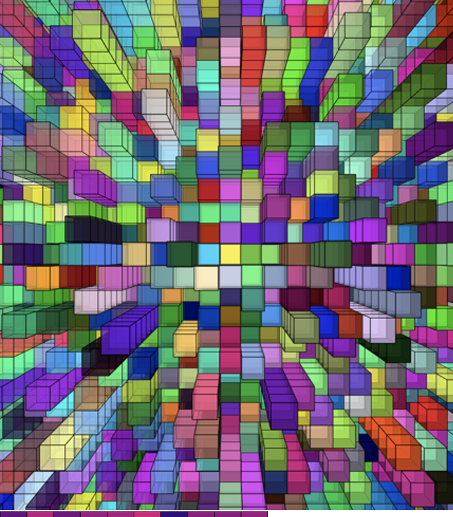
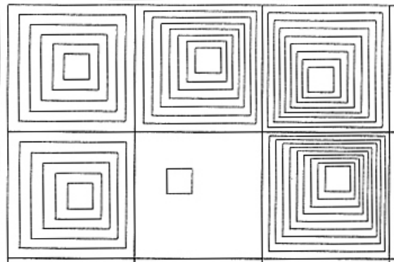
This article really pushed me into thinking about how I could improve my p5.js sketches to make them more interactive. Right now, for the assignment I’m doing this week, I feel like its a little bit flat, but they respond, but not in a way that feels satisfying. For instance, you can click a cube and it pops out, but that’s about it. I want to bring in smoother transitions, add more control options, and maybe even layer multiple interactions on top of each other. For example, what if clicking a cube changed its color, or if dragging across the screen triggered more than one animation? That’s the kind of engaging interaction the article talks about, and it’s the direction I want to head in. I really believe that real interaction should be immersive, and I think the article agrees on that too . I mean, from what I understood, its not about one thing happening at a time; its about creating a system that is consistently reacting to the user. In the future, I want my own projects to feel like they are alive and responding, not just a list of functions that don’t change.