Finalised Concept
For my final project, I am designing an interactive multiplayer game system inspired by the iconic Yu-Gi-Oh! duel disk, but reimagined for creative, social play. Players use physical cards embedded with unique identifiers (such as RFID or NFC tags) to represent custom characters they create. These cards are scanned by an Arduino-powered duel disk, allowing each player to join the game with their personalized avatar and stats. The system supports multiple players competing in a series of mini-games or trivia challenges, with all real-time visuals and game logic handled by a p5.js interface on the computer.
This project merges tangible interaction (physical cards and duel disk) with digital feedback (customizable avatars, live scores, and dynamic mini-games), creating a seamless, engaging experience that emphasizes both individual expression and social play.
Arduino Program Design
Inputs:
-
Multiple RFID/NFC readers (or a shared reader for sequential scans), each detecting when a player places their card on the duel disk.
-
Optional: Buttons or touch sensors for additional in-game actions.
Outputs:
-
LEDs, buzzers, or vibration motors embedded in the disk to provide physical feedback (e.g., indicate successful scans, turns, or game outcomes).
Communication:
-
When a card is scanned, Arduino reads the card’s unique ID and sends it to the computer via serial communication.
-
Arduino can also receive commands from p5.js (e.g., to trigger LEDs or buzzers when a player wins a round).
Summary of Arduino’s Role:
-
Listen for card scans and input actions.
-
Transmit card IDs and sensor data to p5.js promptly.
-
Receive feedback commands from p5.js to control physical outputs.
p5.js Program Design
Responsibilities:
-
Listen for incoming serial data from the Arduino (card IDs, button presses).
-
Match each card ID to a player profile, loading their custom character (name, avatar, stats).
-
Allow players to customize their characters through a user-friendly interface.
-
Manage the game flow: let multiple players join, select mini-games, and track scores.
-
Display real-time game visuals, avatars, and results.
-
Send commands back to Arduino to trigger physical feedback (e.g., light up the winning player’s section).
Data Flow:
-
On card scan: p5.js receives the ID, loads or prompts for player customization, and adds the player to the game.
-
During play: p5.js updates visuals and scores based on game logic and player actions.
-
On game events: p5.js sends output commands to Arduino for physical feedback.
Interaction Design
-
Joining the Game: Each player places their card on the duel disk. The Arduino detects the card, and p5.js loads their profile or prompts for customization.
-
Customizing Characters: Players can use the p5.js interface to personalize their avatars, choose stats, and save progress.
-
Starting a Game: Once all players have joined, they select a mini-game or trivia challenge.
-
Gameplay: Players compete head-to-head or in teams, with p5.js managing the game logic and displaying results. Physical feedback (lights, sounds) enhances the experience.
-
Winning and Progression: Scores and achievements are tracked per player, and leaderboards are displayed at the end of each round.
System Communication
-
Arduino → p5.js: Sends card IDs and sensor/button states.
-
p5.js → Arduino: Sends commands to trigger LEDs, buzzers, or other outputs based on in-game events.
Project Progress and Next Steps
-
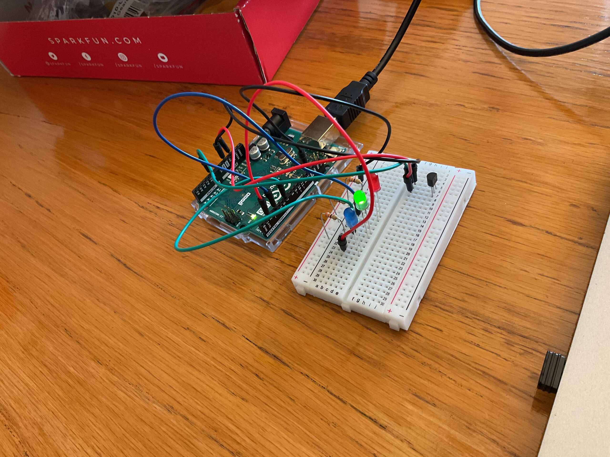
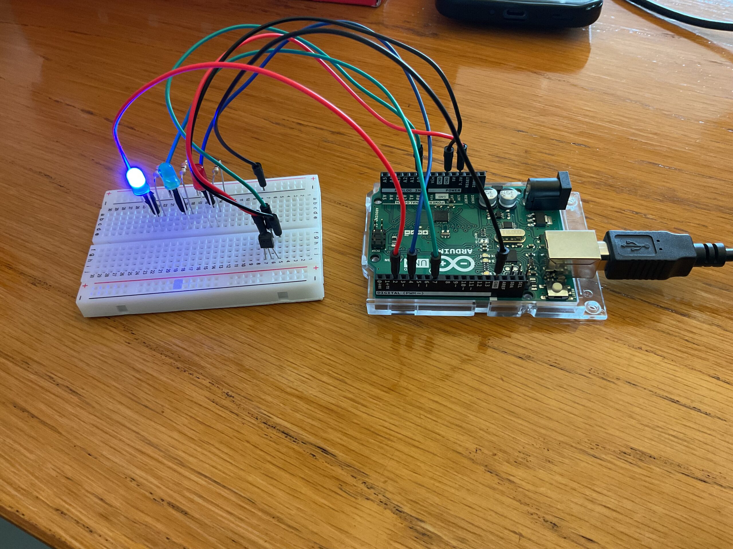
Prototyping: I am currently prototyping the card scanning system with Arduino and testing serial communication with p5.js.
-
UI/UX: Early sketches for the p5.js interface focus on clear avatar displays, easy customization, and intuitive game flow.
-
Game Logic: I am developing the first mini-game (a trivia challenge) and designing the multiplayer logic to support dynamic player counts.
Why This Project?
This system blends physical and digital interaction in a way that is social, customizable, and fun. It encourages users to invest in their characters and compete or collaborate with others, making every session unique. The project leverages Arduino for timely, tangible sensing and feedback, while p5.js handles multimedia processing and engaging visual responses- fulfilling the assignment’s requirements for a responsive, multimedia interactive system.