Concept & Inspiration
As part of the 6th Assignment of Intro to IM, we were tasked with the objective of reading input from at least one analog sensor, and at least one digital sensor (switch). This data would then be used to control at least two LEDs, one in a digital fashion and the other in an analog fashion, in some creative way.
I have always had a great emphasis on the ‘lighting’ around me, and therefore am fond of purchasing different lamps and setting them up to have a good ambiance. This brings me to an interesting lamp I saw once at the convenience store, called Mood Lamp. If you are not aware of what those are, the following video should help you get an idea of it:
Therefore, being inspired from the concept of a ‘switching’ light and wanting to add some additional functionality to it, I decided to test my Arduino and Circuit Making skills to implement a model Mood Lamp. The concept was to use the button or switch as the digital sensor and the light sensor as the analog sensor (controlled by another button) which modifies the brightness of the light. The primary button would be used to modify the color modes of the LED, and a secondary button would toggle the brightness functionality of the light sensor.
Implementation
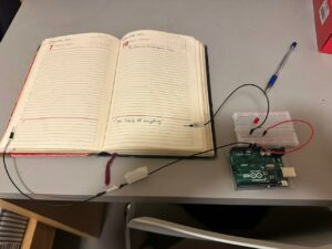
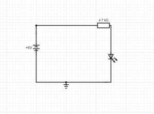
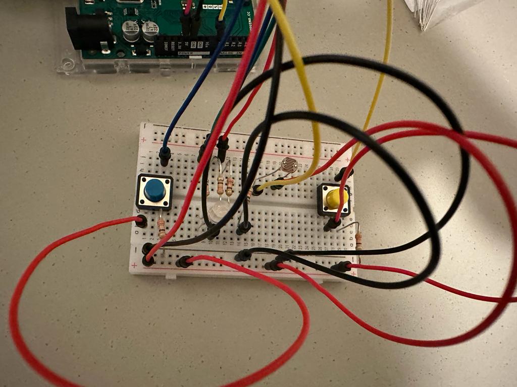
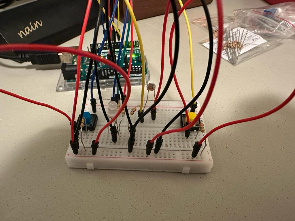
Pictures of Circuit
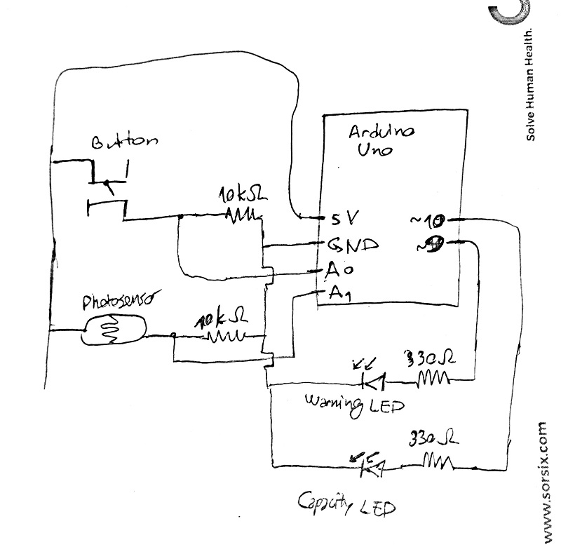
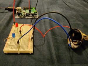
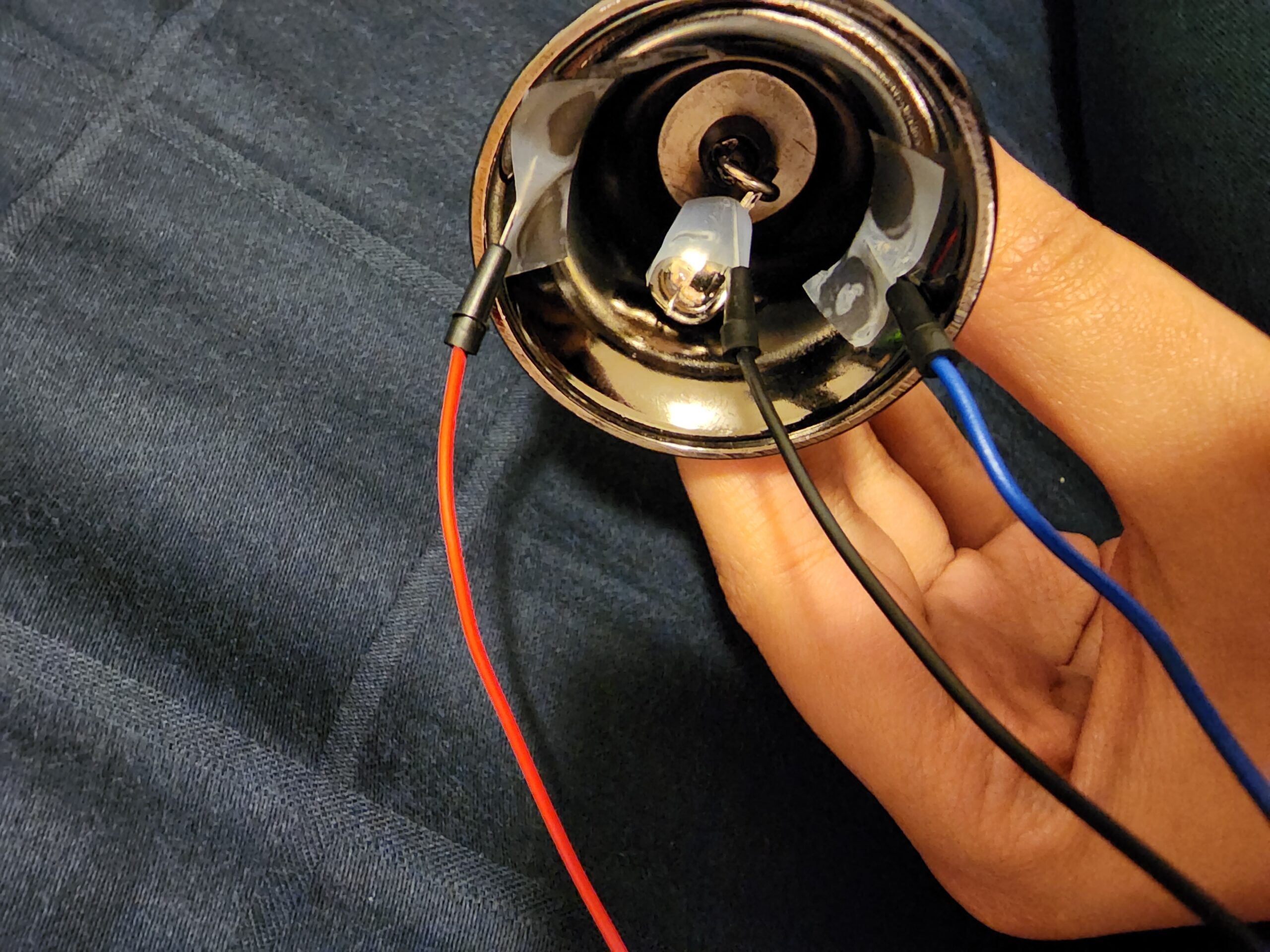
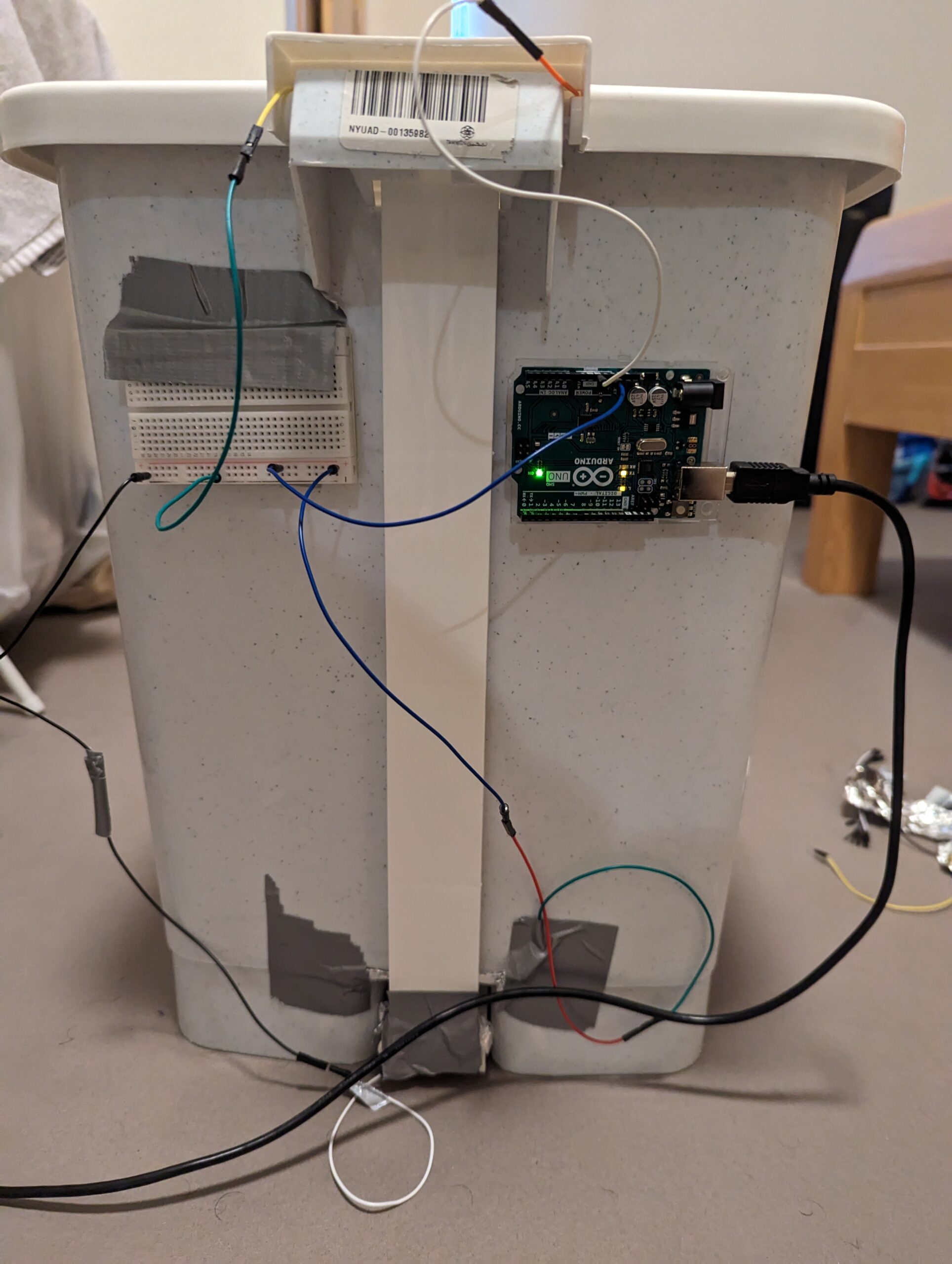
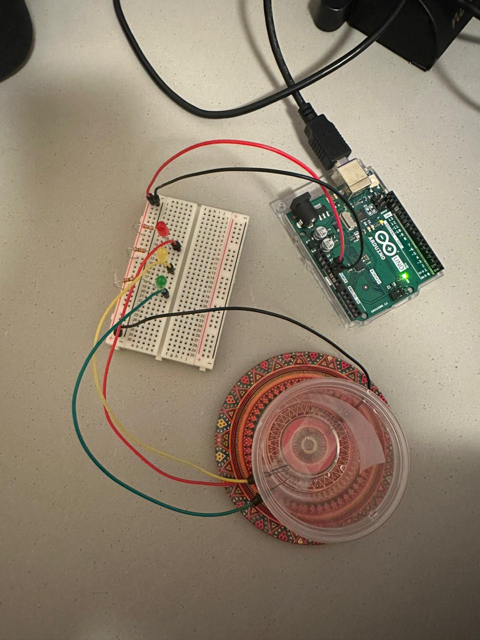
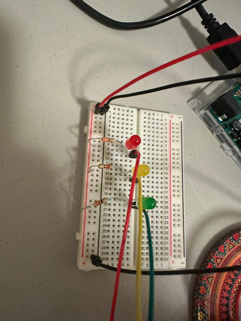
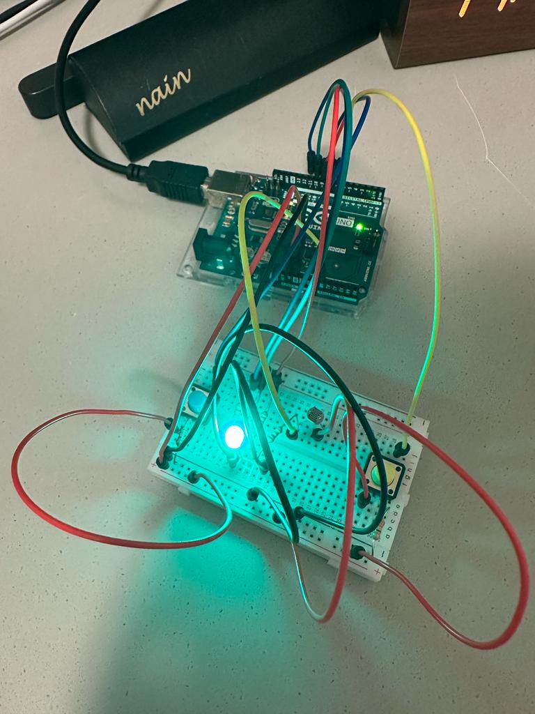
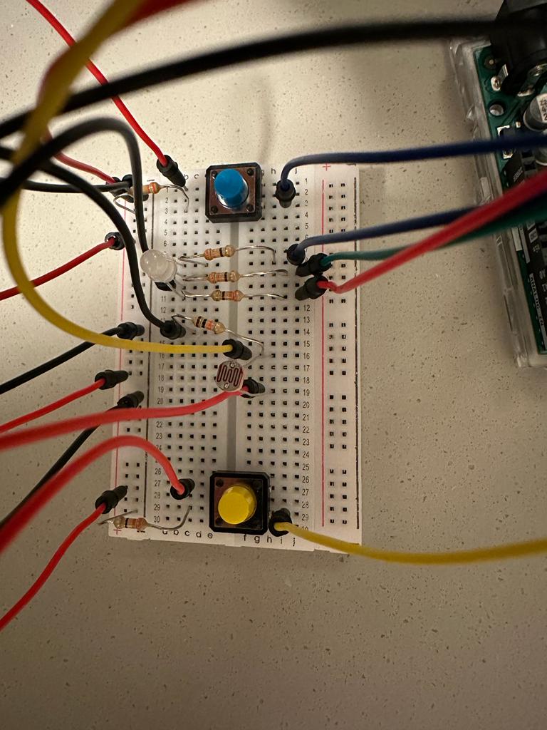
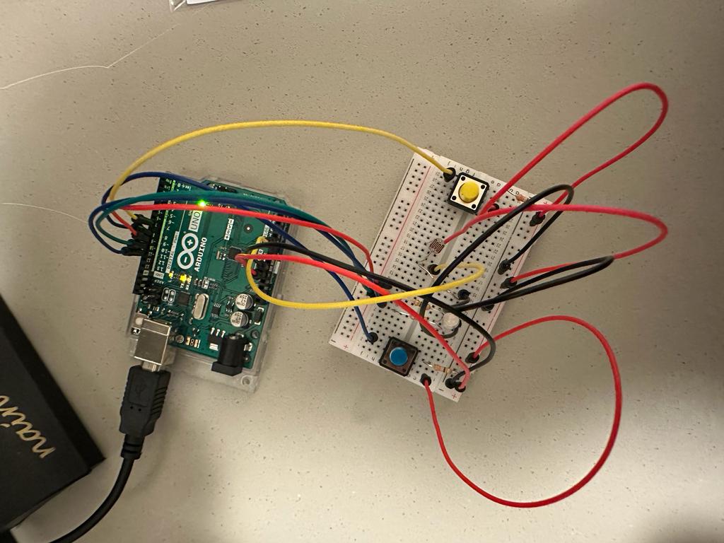
With this, I produced the following circuit:
Demo Video
A demo video, in detail, can be seen here:
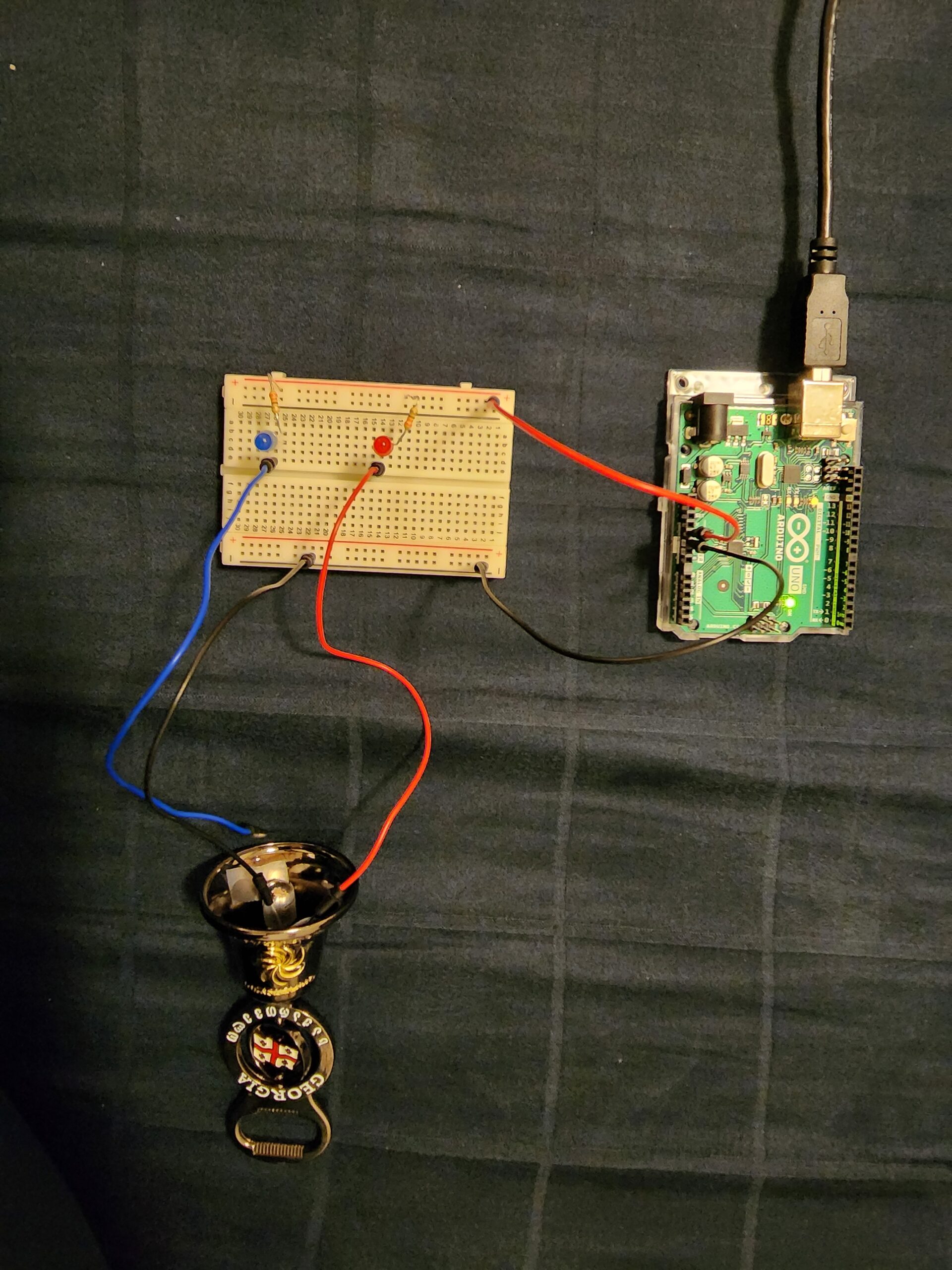
The implementation of the Mood Lamp on the breadboard can be seen above. To make it clear, since the quality of Video did not allow the RGB LED Bulb to be captured to perfection, the Switch on the right, Yellow colored, is used to switch between the different modes of light. In our case, the modes are: Switched Off, Rainbow (Fading), Blue, Green, and Red. Alongside this, the blue button on the left, toggles the brightness adjustment option by making use of the light sensor. The meaning of this is, if the light in the room is brighter, the bulb will glow brighter, and if the light is less, it will grow lighter. Since it is a mood lamp, usually used at night, the purpose of it is to adapt with the light. At night, it should automatically adapt to the surrounding light to make its own light visible.
Code
Since the Code cannot be linked with Arduino, unlike P5js, I will be pasting the entire code here for anyone’s reference!
// Declaration of Constants
const int BUTTON_PIN_LIGHT = 7;  // Connecting the Light Button to Pin 7
const int BUTTON_PIN_LDR = 8;  // Connecting the Photoresistor Button to Pin 7
const int PIN_RED   = 9; //Red LED connected on pin 9
const int PIN_GREEN = 10; //Green LED connected on pin 10
const int PIN_BLUE  = 11; //Blue LED connected on Pin 11
const int LIGHT_SENSOR_PIN = A0; // Connecting the Photoresistor to Pin A0

//Color intensities and direction
//Initial Values for the Fading Rainbow Color Mode
int red             = 254;
int green           = 1;
int blue            = 117;
int red_direction   = -1;
int green_direction = 1;
int blue_direction  = -1;

// Function to set the color of the RGB LED
void setColor(int R, int G, int B) {
  analogWrite(PIN_RED,   R);
  analogWrite(PIN_GREEN, G);
  analogWrite(PIN_BLUE,  B);
}

// Declaration of changing variables
int ledState = 1; // tracks the current state of LED
int ldrState = 1; // tracks the current state of LED
int lastlightButtonState; // the previous state of the light button
int currentlightButtonState; // the current state of the light button
int lastLDRButtonState; // the previous state of the ldr button
int currentLDRButtonState; // the current state of the ldr button
int analogValue; // tracks the light intensity from the LDR
int brightness; // tracks the brightness extracted from the analog Input

void setup() {
  Serial.begin(9600);
  // Settings the Inputs and Outputs of the previously specified pins
  pinMode(BUTTON_PIN_LIGHT, INPUT);
  pinMode(PIN_RED,   OUTPUT);
  pinMode(PIN_GREEN, OUTPUT);
  pinMode(PIN_BLUE,  OUTPUT);
  // Detect initial values of the buttons
  currentlightButtonState = digitalRead(BUTTON_PIN_LIGHT);
  currentLDRButtonState = digitalRead(BUTTON_PIN_LDR);
}

void loop() {
  lastlightButtonState  = currentlightButtonState; // Store Previous State of the light button
  currentlightButtonState = digitalRead(BUTTON_PIN_LIGHT); // Get new state of the light button
  // Same for the LDR Button
  lastLDRButtonState  = currentLDRButtonState;
  currentLDRButtonState = digitalRead(BUTTON_PIN_LDR);

  // Gets the Analog Value from the LDR Sensor
  Serial.print("Light Sensor Value: ");
  analogValue = analogRead(LIGHT_SENSOR_PIN); // read the input on analog pin
  Serial.println(analogValue);

  // Detects if there has been a change in the state of the switch - if it has been pressed
  if(lastLDRButtonState == HIGH && currentLDRButtonState == LOW) {
    Serial.println("LDR (Blue) Button is pressed: ");
    // Change state of LDR Switch
    if(ldrState == LOW) {
       ldrState = HIGH;
       Serial.println("Turning Brightness Variation on");
    }
    else {
      ldrState = LOW;
      Serial.println("Turning Brightness Variation off");
    }
  }

  if (ldrState==HIGH){  // If the Brightness option has been switched on
    brightness = map(analogValue, 0,1023, 0, 255);
  }
  else{ // Otherwise
    brightness = 255;
  }

  // If the light button has been toggled
  if(lastlightButtonState == HIGH && currentlightButtonState == LOW) {
    Serial.print("Light (Yellow) Button is pressed: ");

    Serial.println(ledState);

    // Change the state of LED
    if(ledState == 0) {
       ledState = 1;
       setColor(0, 0, 0); //set LED to Off
    }
    else if (ledState == 1){
      ledState = 2;
      Serial.println("Turning LED Rainbow");
    }
    else if (ledState == 2){
      ledState = 3;
      Serial.println("Turning LED Blue");
    }
    else if (ledState == 3){
      ledState = 4;
      Serial.println("Turning LED Green");
    }
    else{
      ledState = 0;
      Serial.println("Turning LED Red");
    }
  }
  // Changing the colors of the LEDs depending on the State they should be in
  if (ledState == 2){
      red = red + red_direction;
      green = green + green_direction;
      blue = blue + blue_direction;

      // Change direction for each color if it reaches 255
      if (red >= brightness || red <= 0)
      {
        red_direction = red_direction * -1;
      }
      if (green >= brightness || green <= 0)
      {
        green_direction = green_direction * -1;
      }
      if (blue >= brightness || blue <= 0)
      {
        blue_direction = blue_direction * -1;
      }
      setColor(red, green, blue);
  }
  else if (ledState == 3){
    setColor(0, 0, brightness); //set LED to Blue
  }
  else if (ledState == 4){
    setColor(0, brightness, 0); //set LED to Green
  }
  else if (ledState == 0){
    setColor(brightness, 0, 0); //set LED to Red
  }
}

// References taken from:
// https://www.thegeekpub.com/277872/arduino-rgb-led-tutorial/
// https://www.thegeekpub.com/275412/use-a-button-to-toggle-an-led-arduino-tutorial/
// https://www.thegeekpub.com/275412/use-a-button-to-toggle-an-led-arduino-tutorial/
The code is making use of complex state machines, particularly the ledState, and even the ldrState. These states are toggled with the pressing of buttons, and then ultimately control the modifications to other values
Difficulties & Improvements
As I am controlling the brightness, in the RGB LED, I was able to control the brightness when each individual light was switched on only itself with some discrete value. However, as the values fluctuated for the Rainbow mode, the implementation of the Brightness option did not go as planned:
if (ledState == 2){
    red = red + red_direction;
    green = green + green_direction;
    blue = blue + blue_direction;

    // Change direction for each color if it reaches 255
    if (red >= brightness || red <= 0)
    {
      red_direction = red_direction * -1;
    }
    if (green >= brightness || green <= 0)
    {
      green_direction = green_direction * -1;
    }
    if (blue >= brightness || blue <= 0)
    {
      blue_direction = blue_direction * -1;
    }
    setColor(red, green, blue);
}
As shown above, I have tried to set the maximum values as the brightness, however, since the values are changing very fast, there is some issue with the brightness not being adjusted with the above code. I have tried to implement the usage of MOD, like red%brightness, but that has resulted in no effort either!