Ideation
In this week’s assignment we are expected to create a Musical Instrument. Initially we planned to create a Marble Shaker- using the Servo to shake a box of marble from both sides. That was not quite successful because either the box would move completely or not move at all. We were fixated on using the servo and it just clicked about hit sticks on a box using the servo.
Final Product
We used the Ultrasonic sensor to change the speed of the Servo i.e. the hands of the Slap-O-Meter. The closer an object gets to the sensor, the faster the hands moves. The hands are adjusted at an angle to the box so regardless of the speed, it hits the box properly. Here is the code that we used to control the servo and the ultrasonic sensor:
Reflection
We had a lot of fun implementing it! No major challenges apart from some software issues on my laptop and so we just ended up connecting both Arduino to Hind’s laptop.
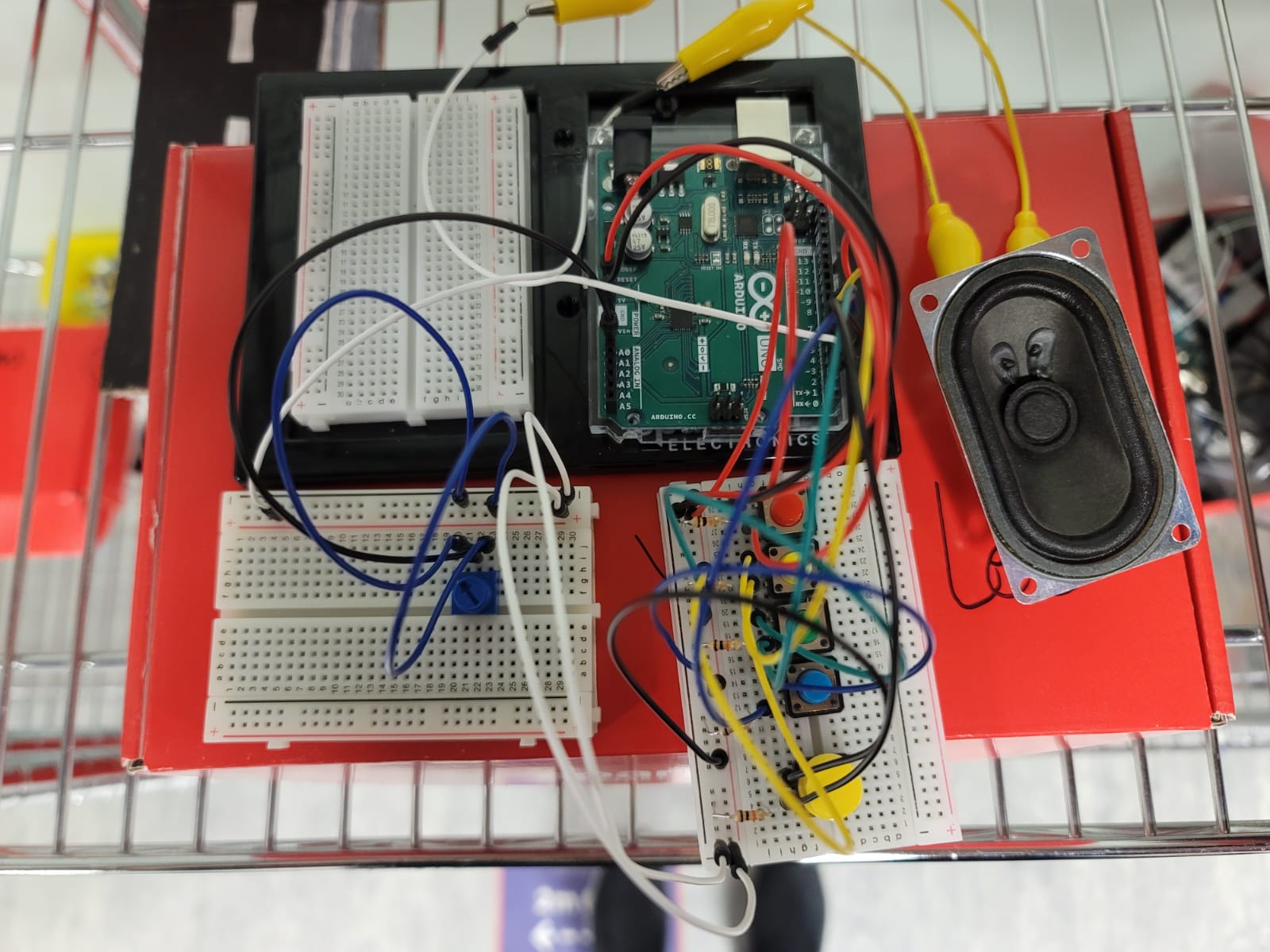
We made a very simple toy electric guitar that anyone can use and make music with just by pressing the buttons in the right order. The tempo of the notes can also be changed using the potentiometer, which challenges the user by seeing how quick they can play the guitar.
Initially, we wanted to use the potentiometer to change the volume of the speakers and we managed to use the potentiometer as a variable resistor almost to change how much current went into the speaker, but the speakers only got soft in the middle range of the potentiometer and got louder at the two extremes, which is unsuitable to use as a switch. Because of this we decided to use it to change the tempo of the notes instead.
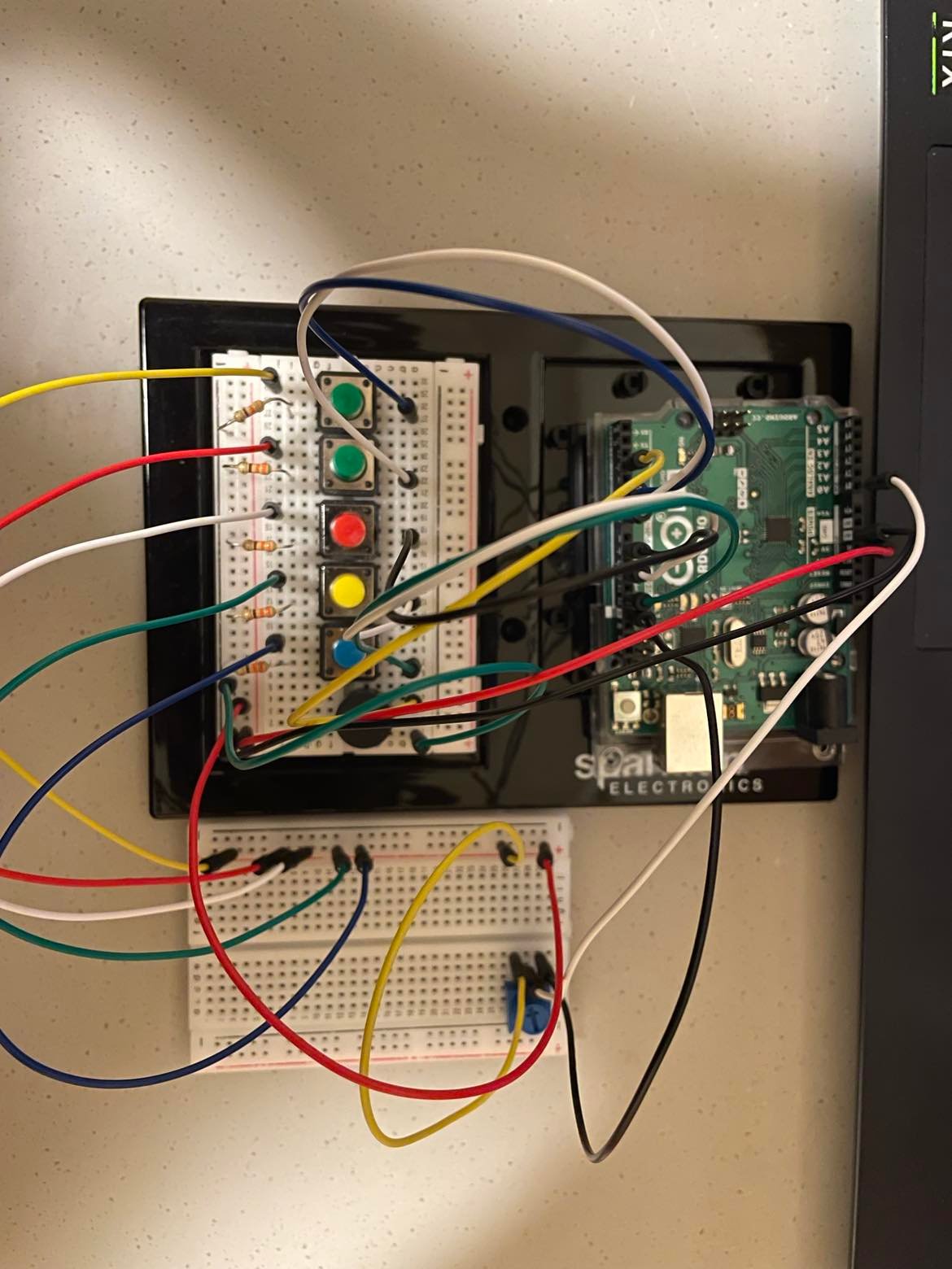
Below is an image of the circuit.
Here is the code and video:
#include "sound.h"

int counter = 0;
int group = 0;
int playMode = 0;

byte But1, PBut1, But2, PBut2, But3, PBut3, But4, PBut4, But5, PBut5;

bool lastnote = false;

int But1Note [] = {NOTE_A2, NOTE_B2, NOTE_C3, NOTE_D3, NOTE_E3, NOTE_F3, NOTE_A3, NOTE_B3, NOTE_C4};
int But2Note [] = {NOTE_B2, NOTE_C3, NOTE_D3, NOTE_E3, NOTE_F3, NOTE_G3, NOTE_D4, NOTE_C4, NOTE_B3};
int But3Note [] = {NOTE_C3, NOTE_D3, NOTE_E3, NOTE_F3, NOTE_G3, NOTE_A3};

int ending [] = {NOTE_A5, NOTE_G5, NOTE_F5, NOTE_E5, NOTE_D5, NOTE_C5, NOTE_B4, NOTE_A4, NOTE_G4, NOTE_E5, NOTE_D5, NOTE_C5, NOTE_B4, NOTE_A4, NOTE_G4, NOTE_F4, NOTE_E4, NOTE_D4, NOTE_C4, NOTE_B3, NOTE_A3};

int play[3];

int octave = 0;

int toneNum;
unsigned long timer = 0;
unsigned long timer2 = 0;

void setup() {
  pinMode(2, INPUT);
  pinMode(3, OUTPUT);
  pinMode(4, INPUT);
  pinMode(5, INPUT);
  pinMode(6, INPUT);
  pinMode(7, INPUT);

  Serial.begin(9600);
}

void loop() {

  if (millis() > timer2) {
    // 3 Buttons that plays 3 notes of the guitar solo
    But1 = digitalRead(7);
    if (But1 == HIGH && PBut1 == LOW) {
      counter = 0;
      for (int i=0; i<3; i++){
        play[i] = But1Note[i+3*group];
      }
    }
    PBut1 = But1;

    But2 = digitalRead(6);
    if (But2 == HIGH && PBut2 == LOW) {
      counter = 0;
      for (int i=0; i<3; i++){
        play[i] = But2Note[i+3*group];
      }
    }
    PBut2 = But2;

    But3 = digitalRead(5);
    if (But3 == HIGH && PBut3 == LOW) {
      if (group == 2) {}
      else{
        counter = 0;
        for (int i=0; i<3; i++){
        play[i] = But3Note[i+3*group];
        }
      }
    }
    PBut3 = But3;

    // this button switches the notes to the next group of the solo
    But4 = digitalRead(4);
    if (But4 == HIGH && PBut4 == LOW) {
      if (group<2){
        group++;
      }
      else group = 0;
    }
    PBut4 = But4;

    // this button switches to the next octave
    But5 = digitalRead(2);
    if (But5 == HIGH && PBut5 == LOW) {
        group = 0;
      if (octave<2){
        octave++;
      }
      else if (octave == 2) {octave++; counter =300;}
      else {octave = 0;}
    }
    PBut5 = But5;

    timer2 = millis() + 10;
  }

  // input from Pot.
  long potVal = analogRead(A0);
  long mapVal = map(potVal, 0, 1023, 100, 350);

  // sound player
  if (millis() > timer) {

    if (counter > 2 && octave !=3) {noTone(3);}
    else if (octave == 3 && counter<21) {tone(3, ending[counter], mapVal+50);}
    else if (octave == 3 && counter>=21) {noTone(3);}
    else{
      tone(3, play[counter]*pow(2,octave), mapVal+50);
    }

    counter++;
    timer = millis() + mapVal;
  }
}
Wouldn’t it be really cool if we built an instrument that made us feel like a DJ? Gathering inspiration from the current use of DJ Consoles and launchpads in the live music industry, we decided on constructing an instrument focused on rhythm and remixing of sounds. We wanted a nice-looking interface that would allow us to modify specific values of sound, and trigger desired notes/mp3’s. But how did we want it to sound?
Have any of you ever asked Siri to beatbox? We had, and so had the internet. From this response from our voice assistant, through which we reference this week’s class discussions, we gave the instrument a name and an initial set of sounds. However, by tapping into the options available by Serial Communication between the P5.js and Arduino, we realized the potential versatility of our instrument. Our instrument did not need to have a specific set of sounds!
Product:
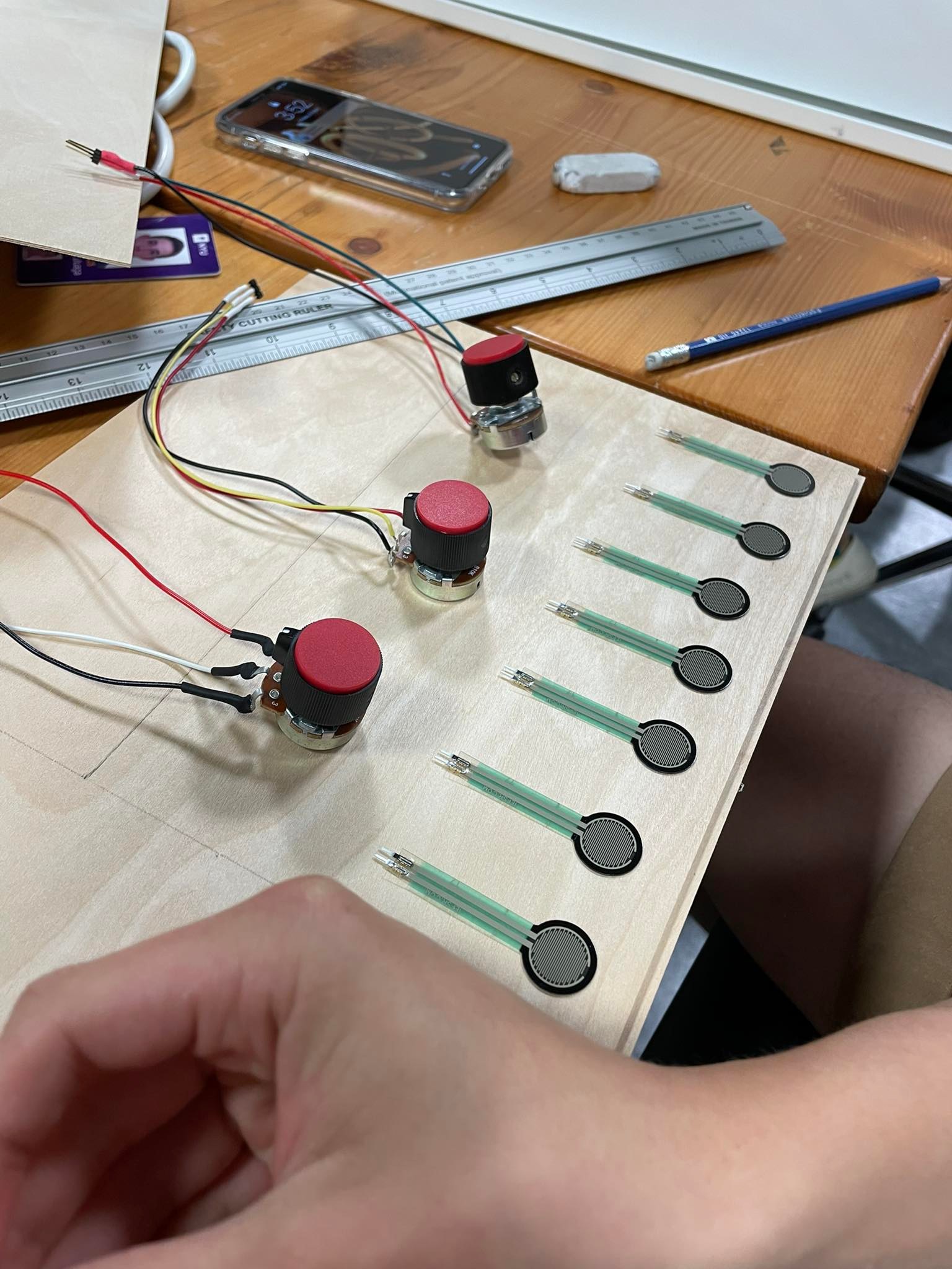
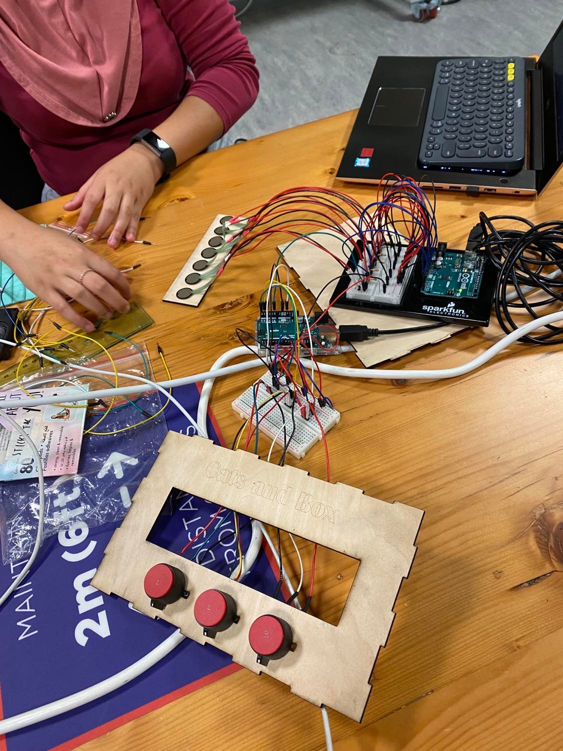
As preparation for the final project, and further Interactive Media endeavors, we wanted to explore the resources available to us in the Interactive Media lab by creating a neat interface and the serial connection. Thus, we built a wooden box with laser-cut sheets that would hold the cables inside/behind. This box has 3 potentiometers, which we soldered that control the volume of 3 different looping sounds. The first one from the left also controls the color of an RGB LED light (which you toggle on/Off with a button) to allow for a more immersive DJ experience. It also has a board with 7 pressure sensors that play a specific sound each.
With the way our code works, you are able to easily upload any .mp3 file to replace the current ones, and thus, completely change the sound of Cats and Box. This makes it similar to a launchpad in that you can completely customize the sounds you input.
Because we had 10 Analog inputs, we had to use two Arduinos, and write two different sets of code. Nevertheless, the premise is the same: We Serial.print a string of the values of each sensor in the arduino. This string is received by P5.js, assigning each value to a specific output. In P5.js we use if statements and variables to control the sounds and volumes.
Here are our codes:
Arduino – Juan’s Laptop
void setup() {
  Serial.begin(9600);
}
void loop() {
  int oneValue = analogRead(A0);

  int twoValue = analogRead(A1);

  int threeValue = analogRead(A2);

  int fourValue = analogRead(A3);

  int fiveValue = analogRead(A4);

  int sixValue = analogRead(A5);


    int sensorValue = oneValue;
    Serial.print(sensorValue);
    Serial.print(",");
    sensorValue = twoValue;
    Serial.print(sensorValue);
    Serial.print(",");
    sensorValue = threeValue;
    Serial.print(sensorValue);
    Serial.print(",");
    sensorValue = fourValue;
    Serial.print(sensorValue);
    Serial.print(",");
    sensorValue = fiveValue;
    Serial.print(sensorValue);
    Serial.print(",");
    sensorValue = sixValue;
    Serial.print(sensorValue);
    Serial.println();
    delay(1);
  }
P5.Js – Juan’s Laptop
Arduino – Lily’s Laptop
const int redPin= 9;
const int greenPin = 10;
const int bluePin = 11;

const int buttonPin = 2;
byte prevButtonState = LOW;
int currentButtonState;

unsigned long timer = 0;
bool blinking = false;
bool onOff = LOW;

const int colour_number = 7;
int ledState = LOW;

void setup() {
  Serial.begin(9600);
  pinMode(redPin, OUTPUT);
  pinMode(greenPin, OUTPUT);
  pinMode(bluePin, OUTPUT);
  currentButtonState = digitalRead(buttonPin);
}

void loop() {
int potValue1 = analogRead(A3);
int colourChoice = potValue1 / (1024 / colour_number);

//for checking if circuit is on or off
  byte currentButtonState = digitalRead(buttonPin);


  if(currentButtonState == HIGH && prevButtonState == LOW) {

    // toggle state of LED
    ledState = !ledState;

    // control LED arccoding to the toggled state

  if (colourChoice > colour_number - 1) {
    colourChoice = colour_number - 1;
  }

  else if (colourChoice == 0) {
    SetColor(18, 221, 54);
  }
  else if (colourChoice == 1) {
    SetColor(235, 242, 39);
  }
  else if (colourChoice == 2) {
    SetColor(234, 31, 37);
  }
  else if (colourChoice == 3) {
    SetColor(0, 255, 0);
  }
  else if (colourChoice == 4) {
    SetColor(249, 88, 212);
  }
  else if (colourChoice == 5) {
    SetColor(29, 33, 168);
  }
  else if (colourChoice == 6) {
    SetColor(0, 193, 249);
  }
  } else {
    digitalWrite(redPin, LOW);
    digitalWrite(greenPin, LOW);
    digitalWrite(bluePin, LOW);
    }
 // Serial.println(potValue1);
 // read the incoming byte - always read whether you need that info or not
   int inByte = Serial.read();

   int sensorValue = analogRead(A0);
    Serial.print(sensorValue);
    Serial.print(",");
    sensorValue = analogRead(A1);
    Serial.print(sensorValue);
    Serial.print(",");
    sensorValue = analogRead(A2);
    Serial.print(sensorValue);
    Serial.print(",");
    sensorValue = analogRead(A3);
    Serial.print(sensorValue);
    Serial.println();
    delay(300);
  }

void SetColor(int R, int G, int B) {
  analogWrite(redPin,   R);
  analogWrite(greenPin, G);
  analogWrite(bluePin,  B);
}
P5.Js – Lily’s Laptop
Process:
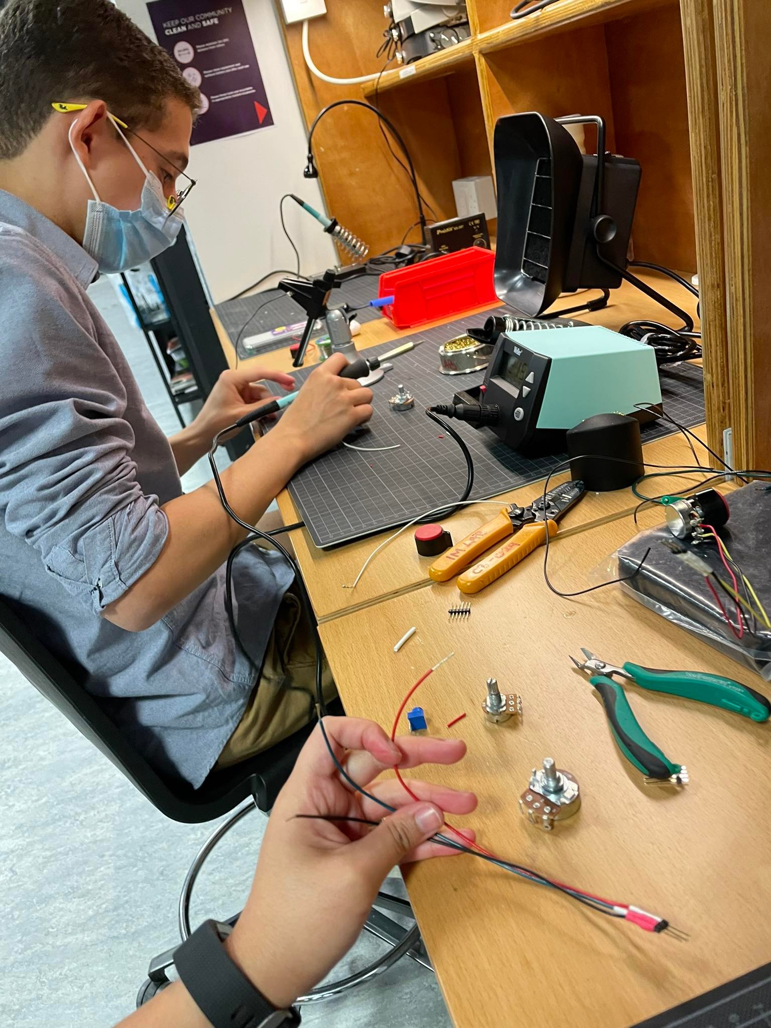
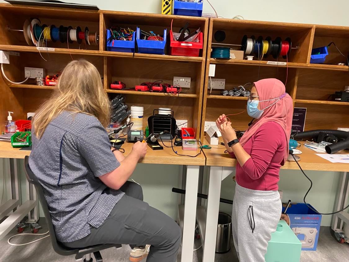
As previously mentioned, we needed to learn and study a lot to build Cats and Box. The first step was learning how to solder. During last week, Kyle Adams and other IM lab assistants were explaining the process to us, guiding us through safety procedures, and helping us with the brainstorming. Kyle, Zion and Alima dedicated a lot of time to guide us through the laser cutting for the box. Without them, we would be very very lost. Once we figured out our interface, building the code with the Serial connection was a big challenge. We struggled to understand the “handshake” and had to watch a few tutorials and read many, many articles to properly manipulate and update the code. Nick and Shamma were an incredible support for us. After many hours of work, we got everything functioning. And then, it was only a matter of assembly and fine-tuning.
Some pictures –
Here is our Final Product:
Reflection:
Juanma: I am very very proud of how our instrument looks. It is the product of countless hours spent in the IM lab and a representation of our steep learning curve. We decided to include many elements that were optional/outside of our scope in order to strengthen our toolbox, and I am very happy we did. In the future, I would like for the sounds to be a bit more seamless, to figure out a way to trigger them multiple times in a row without having to wait for it to end or creating noise, and to include a laser cut space for the LED and cables. However, these are the things that we will keep in mind in future projects and that don’t take away from the awesomeness of Cats and Box. Furthermore, I am very grateful for all the IM students and staff that were more than eager to teach us and help us reach our goal.
Lily: This assignment felt more like a final project than it does a weekly assignment – it took us several late nights to get the p5.js code functioning alongside the arduino. The arduino code was straightforward and it was fun to figure out how to work the RGB lights and button in line with that. However, more work definitely needs to be done to understand integrating sound through p5.js and arduino. Overall I’m very happy with what we came up with and working with Juan was seamless – he was good at things that I’m not good at and vice versa. I’m also very very thankful for Kyle and other IM lab assistants who were very happy to teach us new things like soldering, which truly is what made the mechanics of our instrument work.
For this week’s assignment, we have created a drum with an electronic sound. The idea is that you can control drum sticks (pencils) by tapping the press sensors. To move the drum sticks, we attached them to servo controllers and taped them to the box.
We also have added the button as a digital read, so that a user can change the producing sound. There are four modes of playing the instrument. You can play it by producing sound yourself or by adding extra notes to your play.
To provide a louder sound, we used a speaker instead of a buzzer. After finishing with the functioning part of the work, we decided to add led lights, which would light up whenever the drum sticks touch the box.
#include <Servo.h>
#include "pitches.h"

Servo drum1;
Servo drum2;

int drum1Pin = 5;
int drum2Pin = 3;
int ledPin1 = 8;
int ledPin2 = 2;
int switchPin = 7;
int speaker = 6;

int prevButton;

// play sound or not
bool buzzer = false;


int interval = 250;
unsigned long timer1 = 0;
unsigned long timer2 = 0;

// play different notes with drum beat
int index = -1;
int notes[] = {NOTE_D5, NOTE_F4, NOTE_C4};

void setup() {
  drum1.attach(drum1Pin);
  drum2.attach(drum2Pin);
  pinMode(ledPin1, OUTPUT);
  pinMode(ledPin2, OUTPUT);
  pinMode(switchPin, INPUT);
  pinMode(speaker, OUTPUT);
  pinMode(speaker2, OUTPUT);
}

void loop() {
  int force1 = analogRead(A0);
  int force2 = analogRead(A1);

  int button = digitalRead(switchPin);

  if(button == 1 && prevButton == 0){
    if (index == -1){
      buzzer = true;
      index++;
    }
    else if (index == 2){
      buzzer = false;
      index = -1;
    }
    else{
      index++;
    }
  }

  prevButton = button;

  if(force1 > 800){
    // move the servo
    drum1.write(0);
    digitalWrite(ledPin1, HIGH);
    if(buzzer){
      if (index >= 0){
        // play sound as well
        tone(speaker, notes[index], interval*0.25);
      }
    }
  }
  else{
    // timer to allow the servo to return
    if(millis() > timer1){
        drum1.write(40);
        digitalWrite(ledPin1, LOW);
        timer1 = millis() + interval;
    }
  }

  // for the second servo
  if(force2 > 800){
    drum2.write(0);
      digitalWrite(ledPin2, HIGH);
      if(buzzer){
      tone(speaker, notes[index], interval*0.25);
    }
  }
  else{
    if(millis() > timer2){
        drum2.write(50);
          digitalWrite(ledPin2, LOW);
        timer2 = millis() + interval;
    }
  }
}
For this assignment we decided to use pressure sensors to create a synth sound when pressed. We placed our sensors on a box and programmed everything on P5js and connected it with Arduino using serial control.
After getting our sound to work, we quickly realized that our chosen notes (c4,E4,G4,C5) more closely resemble a digital flute. We then aligned our sensors to the side of the box to mimic the setup of a flute, but in the medium of a box. Of course, our flute box has no air involved but the pressure added to the sensor does change the intensity of the sound produced which is pretty similar to how a flute intrinsically works.
We controlled the flow of data with a variable controlled with a switch, and only sent data to p5js if the switch was toggled using the sample code from class.
 while (Serial.available() > 0 && toggled) {

      // read the incoming byte:

    int analogReading = analogRead(FORCE_SENSOR_PIN);

    int analogReading1 = analogRead(FORCE_SENSOR_PIN1);

    int analogReading2 = analogRead(FORCE_SENSOR_PIN2);

    int analogReading3 = analogRead(FORCE_SENSOR_PIN3);

    Serial.print(analogReading);

    Serial.print(",");

    Serial.print(analogReading1);

    Serial.print(",");

    Serial.print(analogReading2);

    Serial.print(",");

    Serial.print(analogReading3);

    Serial.print("\n");

    Serial.println();

  }
To output the sound input by the sensors, we created an array of MonoSynth instances, in which each instance controlled the note being played and the volume.
monoSynth = [

      new p5.MonoSynth(),

      new p5.MonoSynth(),

      new p5.MonoSynth(),

      new p5.MonoSynth(),

  ];

  notes = [‘C4', 'E4', 'G4', 'C5']

function playSynth(i, val) {

  userStartAudio();

  let intval = int(val)

  let note = notes[i];

  // note velocity (volume, from 0 to 1)

  let velocity = intval<100?0:map(intval, 0, 1023, 0, 1);

  // time from now (in seconds)

  let time = 0;


  // note duration (in seconds)

  let dur = 1/6;

  if(intval > 100)

    monoSynth[i].play(note, velocity, time, dur);

}

if (inString.length > 0) {

    let sensors = split(inString, ","); // split the string on the commas

    if (sensors.length == 4) {

      // if there are three elements

      for(let i=0; i < sensors.length; i++){

        playSynth(i, sensors[i]);

      }

    }

  }
Since the velocity parameter in monoSynth.play() is continuous, we were able to map the input value to a value between 0 and 1, so when the user presses a key heavier, the sound plays louder.
We aimed to build a pianoesque instrument, comprising of multiple push switches (as the digital inputs) to play different musical notes (C4, D4, E4, F4, G4). But given our breadboard’s size, we couldn’t attach too many switches for the wide array of notes, so we used a potentiometer (as the analog input) to further expand our range of pitches to play.
#include "pitches.h"

const int buzzerPin = 3;
const int button_C4 = 5;
const int button_D4 = 7;
const int button_E4 = 9;
const int button_F4 = 11;
const int button_G4 = 13;


void setup() {
  // put your setup code here, to run once:

  pinMode(buzzerPin, OUTPUT);
  pinMode(button_C4, INPUT);
  pinMode(button_D4, INPUT);
  pinMode(button_E4, INPUT);
  pinMode(button_F4, INPUT);
  pinMode(button_G4, INPUT);

}

void loop() {
  // put your main code here, to run repeatedly:

  int potValue = analogRead(A0);
  int mappedPotValue = map(potValue, 0, 1023, -200, 200);

  int buttonstate_C4 = digitalRead(button_C4);
  int buttonstate_D4 = digitalRead(button_D4);
  int buttonstate_E4 = digitalRead(button_E4);
  int buttonstate_F4 = digitalRead(button_F4);
  int buttonstate_G4 = digitalRead(button_G4);

  if(buttonstate_C4 == 1)
    {
      tone(buzzerPin, NOTE_C4+mappedPotValue, 50);
    }
    if(buttonstate_D4 == 1)
    {
      tone(buzzerPin, NOTE_D4+mappedPotValue, 50);
    }
    if(buttonstate_E4 == 1)
    {
      tone(buzzerPin, NOTE_E4+mappedPotValue, 50);
    }
    if(buttonstate_F4 == 1)
    {
      tone(buzzerPin, NOTE_F4+mappedPotValue, 50);
    }
    if(buttonstate_G4 == 1)
    {
      tone(buzzerPin, NOTE_G4+mappedPotValue, 50);
    }

}
Hello everyone, here are some questions for tomorrow’s reading discussion:
Before reading this article what were your thoughts on the future of interaction design?
Are you satisfied with current technology like iPhones or iPads for example and you don’t think it really needs to improve much?
we were wondering if you had any ideas as to how hands could be integrated into interaction design in a feasible way?
Do you actually use voice interactions like voice assistants on their phones for example? Do you think voice will play a big role in future interaction design?
Would you disagree and think that brain interfaces could be good? What other problems do you think brain interfaces could lead to?
Do you have any ideas as to how something like haptic gloves could be integrated into our daily lives and replace some of our current technology?
As a final thought, do you agree or disagree with the author’s perspective on the future of interaction design?
After trying to figure out how to integrate the two switches together, I came up with the idea of using the potentiometer to toggle between three different LEDs – red for a bad face, yellow for a medium face and green for a happy face. This would lead to some sort of customer service device to give feedback on how you feel.
So far I have been understanding the wiring pretty well but to connect the coding with making what I want to physically happen has been slightly difficult. It feels difficult for my brain to wrap around. I was doing okay with the coding part of the first half of the semester, and the wiring physical part we’re learning now – but I’m a little slow to combine them.
In terms of creating this project – It was relatively easy to get the button to work (to turn on the blue LED) and to get the potentiometer connected to the three colored LEDs. With a little help from Juan, I was able to connect the two together and make it such that wen the button is pressed, the blue LED turns on and so does the potentiometer LEDs, and when clicked again, the customer service ‘device’ turns off.
const int redLight = 9;
const int yellowLight = 10;
const int greenLight = 11;
const int blueOnLight = 4;
const int button = 5;

const int LED_number = 3;

int ledState = LOW;
int lastButtonState;
int currentButtonState;

void setup()
{
  pinMode(redLight, OUTPUT);
  pinMode(yellowLight, OUTPUT);
  pinMode(greenLight, OUTPUT);
  pinMode(blueOnLight, OUTPUT);
  pinMode(button, INPUT_PULLUP);
  Serial.begin(9600);
  currentButtonState = digitalRead(button);
}

void loop()
{
  int potValue = analogRead(A0);
  int ledChoice = potValue / (1024 / LED_number);

  //for checking if circuit is on or off
  lastButtonState    = currentButtonState;
  currentButtonState = digitalRead(button);

  if(lastButtonState == HIGH && currentButtonState == LOW) {

    // toggle state of LED
    ledState = !ledState;

    // control LED arccoding to the toggled state
    digitalWrite(blueOnLight, ledState);
  }

//for customer service lights

  if (ledState == HIGH){
  if (ledChoice > LED_number - 1) {
    ledChoice = LED_number - 1;
  }

  else if (ledChoice == 0) {
    digitalWrite(redLight, HIGH);
    digitalWrite(yellowLight, LOW);
    digitalWrite(greenLight, LOW);
  }
  else if (ledChoice == 1) {
    digitalWrite(redLight, LOW);
    digitalWrite(yellowLight, HIGH);
    digitalWrite(greenLight, LOW);
  }
  else {
    digitalWrite(redLight, LOW);
    digitalWrite(yellowLight, LOW);
    digitalWrite(greenLight, HIGH);
  }
  } else {
    digitalWrite(redLight, LOW);
    digitalWrite(yellowLight, LOW);
    digitalWrite(greenLight, LOW);
    }
  Serial.println(potValue);
}
Without further ado, I present you with the customer service device:
make something that uses only one sensor on arduino and makes the ellipse in processing move on the horizontal axis, in the middle of the screen, and nothing on arduino is controlled by processing
make something that controls the LED brightness from processing
take the gravity wind example below and make it so every time the ball bounces one led lights up and then turns off, and you can control the wind from one analog sensor
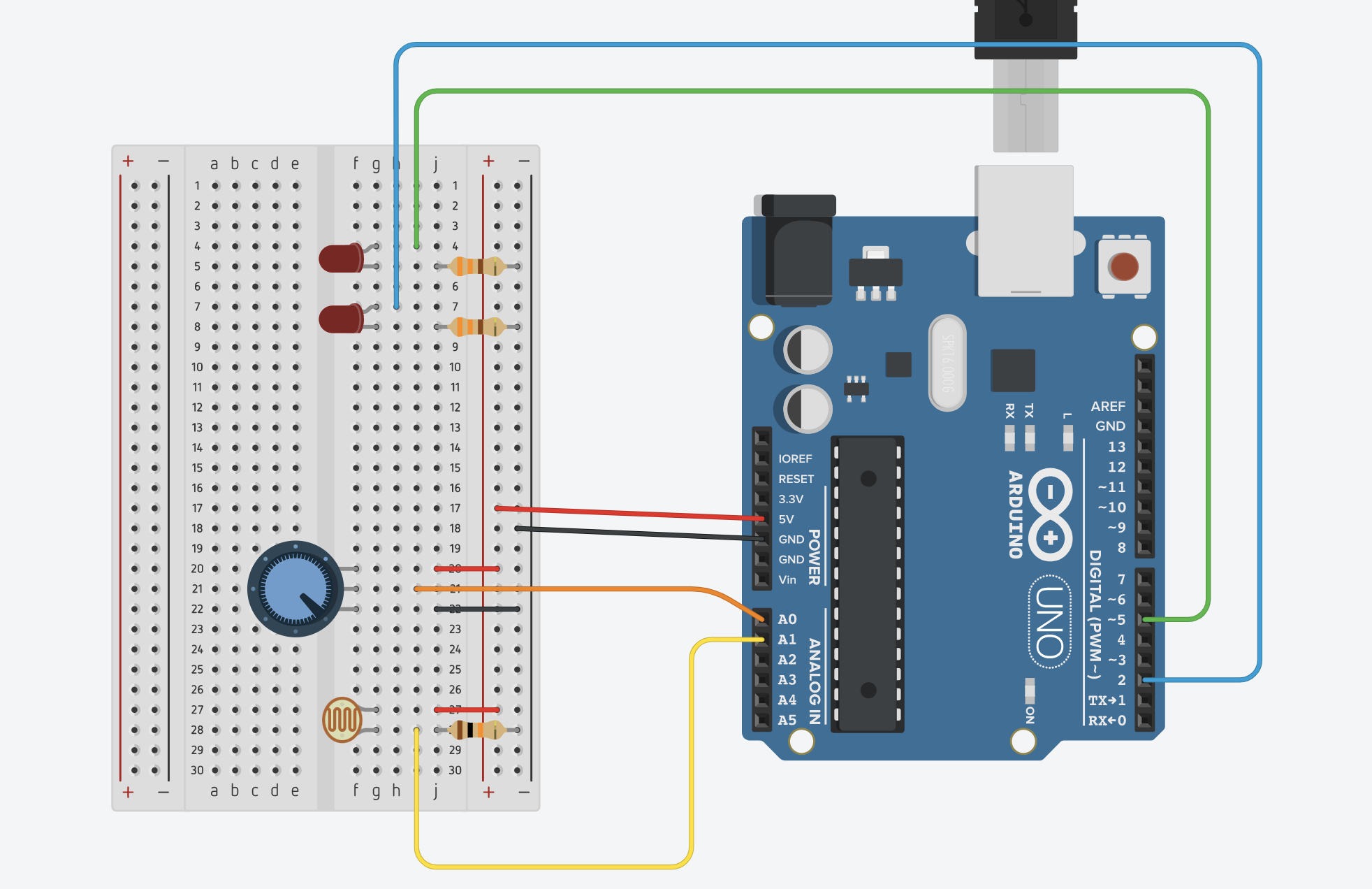
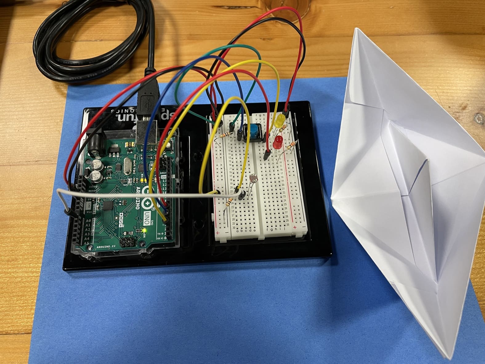
With this assignment I set out to buid a simplified lighthouse using two seperate LEDs.
The yellow LED is controlled by a switch (digital input). So this LED is either turned on or off, similar to how a lighthouse works at set times during the night.
The red LED is dependant on the intensity of light in the environment. It’s brightness is mapped to the resistance of the LDR that varies with light. Therefore, in absence of light, the LDR’s resistance increases, and the LED glows brighter. In real life, this would mean as the sun sets, the lighthouse would emit more light, hence being more visible to far off ships.
These two LED’s represent two plausable ways lighthouses function. The LDR value is read by the analogue input and the switch value is read by the digital inputs.
const int yLedPin = 2;
const int rLedPin = 7;
const int buttonPin = 3;
bool onOff = LOW;
byte prevButtonState = LOW;

void setup() {
  // put your setup code here, to run once:
  pinMode(yLedPin, OUTPUT);
  pinMode(rLedPin, OUTPUT);
  pinMode(buttonPin, INPUT);
  Serial.begin(9600);

}

void loop() {
  // put your main code here, to run repeatedly:
  byte buttonState  = digitalRead(buttonPin);
  int lightValue = analogRead(A0);
//  Serial.println(lightValue);
  int mappedLightValue = map(lightValue, 500, 900, 255, 0);

  int constrainedLightValue = constrain(mappedLightValue, 0, 255);
  analogWrite(5, constrainedLightValue);

  if (buttonState == HIGH && prevButtonState == LOW) {
    // change blinking to not blinking
    onOff = !onOff;
    digitalWrite(yLedPin, onOff);
  }
  prevButtonState = buttonState;

}