Exercise 1: Control p5js through Arduino
For this exercise we had to establish serial communication between p5js and Arduino. Then we had to use an analog sensor to control some values in p5js. I used a photoresistor to control the movement of a circle in p5js.
p5js Code:
// This program reads data from an Arduino board via serial connection and uses the data to control the position of an ellipse drawn on a P5JS canvas.

// Declare a variable to hold the x-coordinate of the ellipse.
let xValue = 0;
// Set up the canvas.
function setup() {
  createCanvas(400, 400);
}
// Draw the ellipse on the canvas and display a message indicating whether or not the serial connection is active.
function draw() {
  background(0);
    // If the serial connection is not active, display a message telling the user to press the space bar to select a serial port.
  if (!serialActive) {
    fill(255);
    text("Press Space Bar to select Serial Port", width/4, 30);
  }
   // If the serial connection is active, display a message indicating that it is connected and draw an ellipse at the current x-coordinate.
  else {
    fill(255);
    noStroke();
    text("Connected", 170, 30);
    stroke(255);
    fill("#39FF14")
    ellipse(xValue, height/2, 50, 50);
  }
}

// Set up the serial connection when the space bar is pressed.
function keyPressed() {
  if (key == " ") {
    setUpSerial();
  }
}

// Read the incoming data from the serial port and map it to the range of the canvas.
function readSerial(data) {
  if (data != null) {
// Map the incoming data from the range of 0 to 1023 to the range of 0 to the width of the canvas.
    xValue = map(data, 840, 0, width, 0);
  }
}
Arduino Code:
// This program reads data from a light sensor connected to analog pin A0 of an Arduino board and sends the data to a serial port (p5js).

// Define the analog pin to which the light sensor is connected.
const int lightSensor = A0;

// Set up the serial connection.
void setup() {
  Serial.begin(9600);

  // Set the light sensor pin as an input.
  pinMode(lightSensor, INPUT);
}

// Read the value from the light sensor and print it to the serial port.
void loop() {
  // Read the value from the light sensor.
  int lightValue = analogRead(lightSensor);

  // Print the light value to the serial port.
  Serial.println(lightValue);
}
Video:
Exercise 2: Control Arduino through p5js
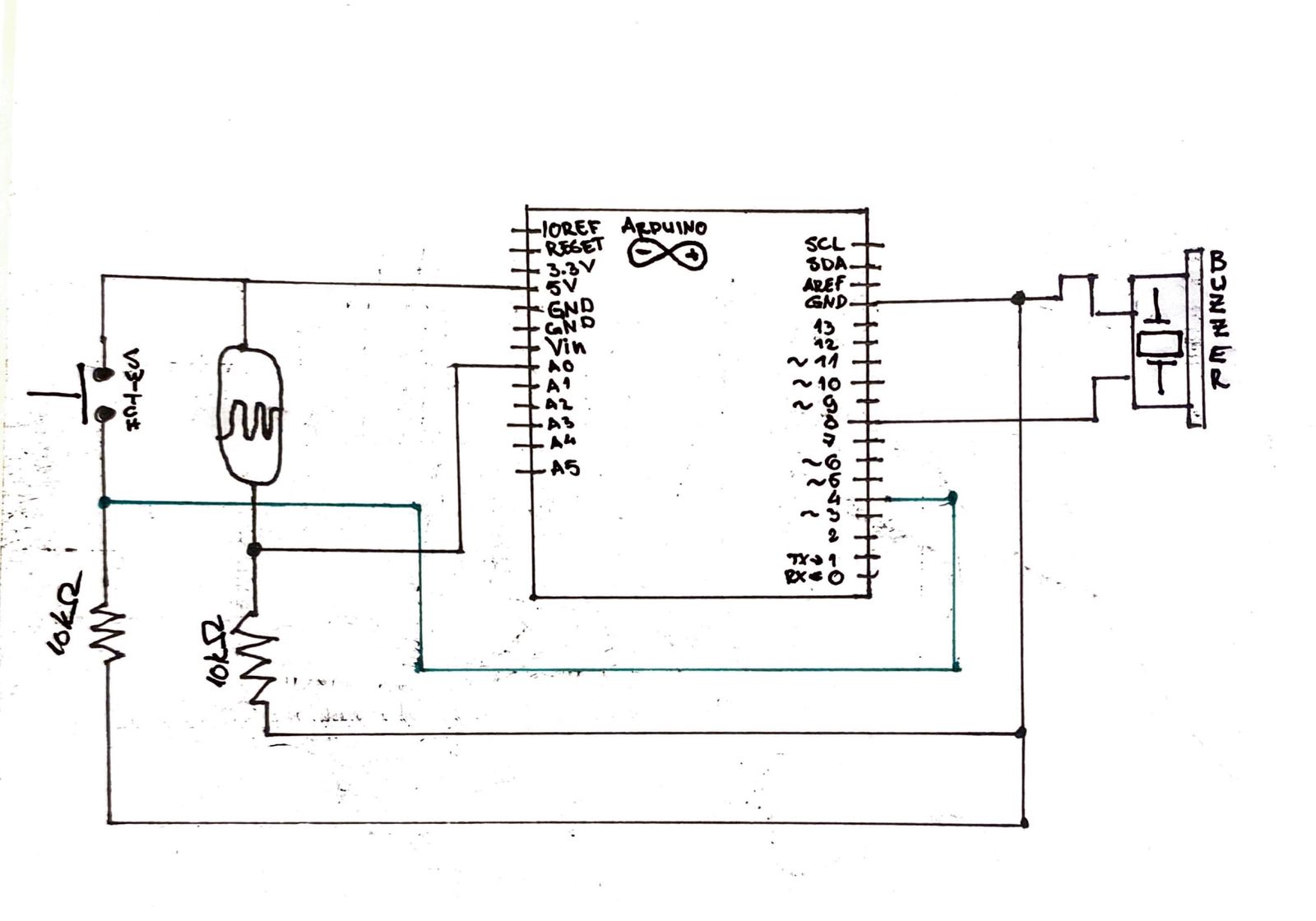
For the second exercise we had to control Arduino through p5js. I designed a circuit with an LED whose brightness was controlled by clicking the mouse in different positions.
P5js Code:
//Declare and intialize the duty variable to 0
let duty = 0;
//Create canvas and set text size to 18
  function setup() {
    createCanvas(640, 480);
    textSize(18);
  }

  function draw() {
  background(0);
    // Check if the serial port is not active
    if (!serialActive) {
      // Display a message to prompt the user to press the space bar to select a serial port
      fill(255);
      text("Press Space Bar to select Serial Port", 20, 30);
    } else {
      fill(255);
      // Display a message indicating that the serial port is connected
      text("Connected", 20, 30);
      // Log the duty value to the console
      console.log(duty);
      // Create a string to send to the Arduino over serial with the duty value and a newline character
      let sendToArduino = duty + "\n";
      // Send the string to the Arduino over serial
      writeSerial(sendToArduino);
    }
   }
  function keyPressed() {
    // Check if the space bar is pressed
    if (key == " ") {
      setUpSerial();
    }
  }
  function mousePressed() {
    // Map the mouseY value to a duty value between 0 and 1023
    duty = int(map(mouseY, 0, height, 0, 1023));
  }
  function readSerial(data) {
  }
Arduino Code:
Unfortunately I lost the Arduino code as I over wrote it with the code from the 3rd exercise without previously saving.
Video:
Exercise 3: Two-way communication between p5js and Arduino
For this exercise we had to establish a two-way communication. I used a photo receptor to control the direction of movement of a circle in p5js, and used p5js to turn on an LED every time that circle hit the ground.
P5js Code:
// Ball simulation variables
let ballVelocity;
let ballGravity;
let ballPosition;
let ballAcceleration;
let ballWind;
let ballDrag = 0.99;
let ballMass = 50;

// Arduino communication variables
let arduinoWindSensorValue = 0;
let arduinoLedOn = 0;

function setup() {
createCanvas(400, 400);
ballPosition = createVector(width/2, 0);
ballVelocity = createVector(0,0);
ballAcceleration = createVector(0,0);
ballGravity = createVector(0, 0.5*ballMass);
ballWind = createVector(0,0);
}

function draw() {
background(0);
fill(255);
if (!serialActive) {text("Press Space Bar to select Serial Port", width/4, 30); }
else {text("Connected!", 165, 30); }

fill("#39FF14");
applyForce(ballWind);
applyForce(ballGravity);
ballVelocity.add(ballAcceleration);
ballVelocity.mult(ballDrag);
ballPosition.add(ballVelocity);
ballAcceleration.mult(0);
ellipse(ballPosition.x,ballPosition.y,ballMass,ballMass);

if (ballPosition.y > height-ballMass/2) {
ballVelocity.y *= -0.9; // A little dampening when hitting the bottom
ballPosition.y = height-ballMass/2;
arduinoLedOn = 1; //If the ball makes contact with the ground, the LED will be ON
}
else {arduinoLedOn = 0;} //Else the LED will be OFF

//If the arduinoWindSensorValue value from the Arduino that was mapped is greater than 0, then it will move the ball to the right
if(arduinoWindSensorValue > 0) {
ballWind.x = 0.5;
}

//Else if the arduinoWindSensorValue value from the Arduino is less than 0, it will move the ball to the left
else if(arduinoWindSensorValue < 0) {
ballWind.x = -0.5;
}

//If it's 0, aka no wind, then it will just keep the ball where it is, no wind.
else {
ballWind.x = 0;
}
}

function applyForce(force){
// Newton's 2nd law: F = M * A
// or A = F / M
let f = p5.Vector.div(force, ballMass);
ballAcceleration.add(f);
}

function keyPressed(){
if (key == "m"){
ballMass=random(15,80);
ballPosition.y=-ballMass;
ballVelocity.mult(0);
}

if(key == " ") {
setUpSerial();
}
}

function readSerial(data) {
if(data != null) {
//Sends the arduinoLedOn information to the Arduino
let sendToArduino = arduinoLedOn + "\n";
writeSerial(sendToArduino);
//Reads the arduinoWindSensorValue values from the Arduino and maps its value to either -1 or 1 to correspond to wind direction.
arduinoWindSensorValue = map(data, 0, 1023, -1 , 1);
}
}
Arduino Code:
// Define pin constants
const int LED_PIN = 8;
const int LIGHT_SENSOR_PIN = A0;

void setup() {
  // Start serial communication
  Serial.begin(9600);

  // Set pin modes
  pinMode(LED_PIN, OUTPUT);
  pinMode(LIGHT_SENSOR_PIN, INPUT);

  // Check LED wiring
  digitalWrite(LED_PIN, HIGH);
  delay(200);
  digitalWrite(LED_PIN, LOW);

  // Wait for serial connection
  while (Serial.available() <= 0) {
    Serial.println("0");
  }
}

void loop() {
  while (Serial.available()) {
    // Read LED ON/OFF information from p5js and switch LED on/off accordingly
    int led_on = Serial.parseInt();
    digitalWrite(LED_PIN, led_on);

    // Read light value from the sensor and send it to p5js
    int light_value = analogRead(LIGHT_SENSOR_PIN);
    Serial.println(light_value);
  }
}
Video:
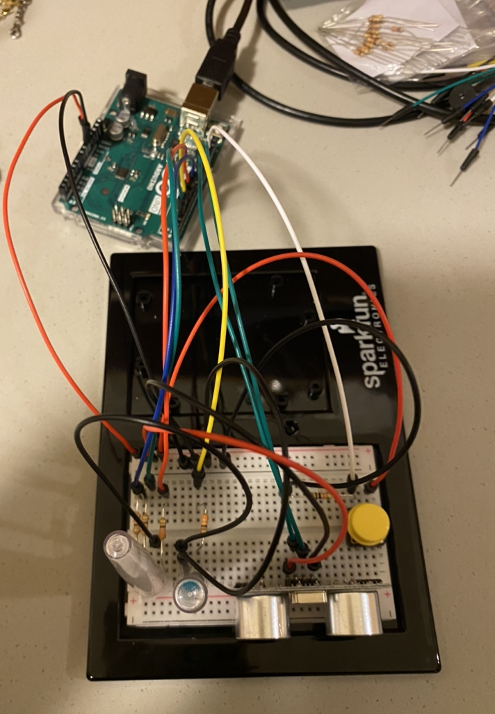
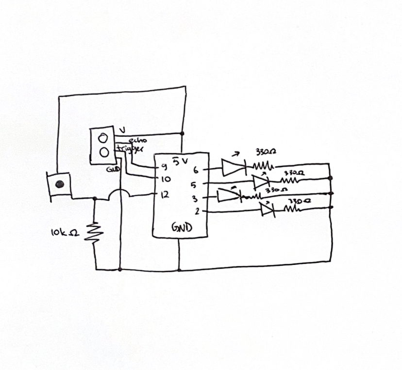
Final Project – Arduino Radar:
The project I am working on involves building a radar system using Arduino and P5JS. The radar will use an ultrasonic sensor to detect objects in the environment and display them on a graphical interface built with P5JS. The graphical interface will show the real-time location of the detected objects on a radar screen, with different colors indicating different distances. This project aims to showcase the capabilities of Arduino in building complex and interactive systems and to demonstrate the potential of radar technology in various applications, such as robotics, security, and environment monitoring. By combining hardware and software, this project will offer a unique and innovative solution for users who are interested in exploring the world of DIY electronics and sensor technology.