FINAL PROJECT IDEA

CONCEPT

For now, my plan is to build a car which will be controlled using hand gestures from the user. To do this, the control system will track the user’s hand position, interpret the hand gestures made by the user and translated the hand gestures into commands that’d be used in moving the car.

IMPLEMENTATION

My goal is to develop a control system for a car by integrating the P5JS tracking system. This system will enable the car to be controlled through hand gestures made by the user. To achieve this, I will utilize the advanced capabilities of PoseNet for detecting the user’s hand position accurately. By interpreting the hand gestures made by the user, the system will translate them into commands that can be used to move the car.

The P5JS tracking system will be responsible for monitoring and analyzing the forward and backward movements of the user’s hand to control the car accordingly. It will allow the user to steer the car in the desired direction by moving their hand forward, backward, left or right. The tracking system will accurately detect the user’s hand position and interpret the hand gestures in real-time, enabling seamless and responsive control of the car.


WEEK 11

PROMPT 1

Code

//declaring variables
let serial;
let photoValue = 0;
let xPos = 0;
let Size = 80;
let yPos = 200;

function setup() {
  createCanvas(400, 400);
  serial = new p5.SerialPort();
  serial.open('/dev/tty.usbmodem1301');
  serial.on('data', readSerialData); // call readSerialData when new data is received
}

function draw() {
  background(220);
  fill("red");
  ellipse(xPos, yPos, Size, Size);
}

function readSerialData() {
  let data = serial.readLine(); // read the incoming data
  if (data) {
    photoValue = Number(data); // convert the data to a number
    xPos = map(photoValue, 0, 1023, 0, width); // map the photo sensor value to the x-position of the ellipse
  }
}

Video


PROMPT 2

CODE

let serial;
let brightness = 0; // variable to store LED brightness

function setup() {
  serial = new p5.SerialPort();
  serial.open('/dev/tty.usbmodem1301');
  createCanvas(400, 400);
}

function draw() {
  background(220);
  text("LED Brightness: " + brightness, 50, 50);

  // send data to Arduino over serial
  if (frameCount % 10 == 0) {
    serial.write(brightness);
  }
}

function keyPressed() {
  if (keyCode === UP_ARROW && brightness < 255) {
    brightness += 10; // increase brightness by 10
  } else if (keyCode === DOWN_ARROW && brightness > 0) {
    brightness -= 10; // decrease brightness by 10
  }
}

VIDEO


PROMPT 3

CODE

let gravity;
let position;
let acceleration;
let wind;
let drag = 0.99;
let mass = 50;
let lightVal = 0;
let ledState = false;

let serial;
let led;

function setup() {
  createCanvas(640, 360);
  noFill();
  position = createVector(width/2, 0);
  velocity = createVector(0,0);
  acceleration = createVector(0,0);
  gravity = createVector(0, 0.5*mass);
  wind = createVector(0,0);

  serial = new p5.SerialPort();
  serial.open('/dev/tty.usbmodem1301');
  serial.on("data", serialEvent);

  led = new p5.SerialPort();
  led.open('/dev/tty.usbmodem1301');
}

function draw() {
  background(255);

  wind.x = map(lightVal, 0, 1023, -1, 1);

  applyForce(wind);
  applyForce(gravity);
  velocity.add(acceleration);
  velocity.mult(drag);
  position.add(velocity);
  acceleration.mult(0);
  ellipse(position.x,position.y,mass,mass);

  if (position.y > height-mass/2) {
    velocity.y *= -0.9;  // A little dampening when hitting the bottom
    position.y = height-mass/2;
    led.write("L"); // Turn off the LED when the ball hits the ground
  } else {
    led.write("H"); // Turn on the LED when the ball is in the air
  }
}

function applyForce(force){
  // Newton's 2nd law: F = M * A
  // or A = F / M
  let f = p5.Vector.div(force, mass);
  acceleration.add(f);
}

function serialEvent() {
  lightVal = Number(serial.readLine());
}

function keyPressed(){
  if (keyCode==LEFT_ARROW){
    wind.x=-1;
  }
  if (keyCode==RIGHT_ARROW){
    wind.x=1;
  }
  if (key==' '){
    mass=random(15,80);
    position.y=-mass;
    velocity.mult(0);
  }
}

VIDEO


Arduino + p5js in class exercises (Saamia and Khadija)

Exercises

Exercise 1:

For our first exercise, we used a light sensor as the analog input value for the movement of the ellipse on the p5js screen. The rVal from Arduino is used to plot the x coordinate of the ellipse.

p5js code:

//exercise 1 p5js
let rVal = 0;
let alpha = 255;

function setup() {
  createCanvas(640, 480);
  textSize(18);
}

function draw() {
  
  if (key == " ") 
  {
    // important to have in order to start the serial connection!!
    setUpSerial();
  }
  
  // one value from Arduino controls the background's red color
  background(map(rVal, 0, 1023, 0, 255), 255, 255);

  // the other value controls the text's transparency value
  fill(255, 0, 255, map(alpha, 0, 1023, 0, 255));

  if (!serialActive) 
  {
    text("Press Space Bar to select Serial Port", 20, 30);
  } else 
  {
    ellipse(rVal/2,240,100,100);
  }
}

function keyPressed() {
  if (key == " ") 
  {
    // important to have in order to start the serial connection!!
    setUpSerial();
  }
}

// This function will be called by the web-serial library
// with each new line of data. The serial library reads
// the data until the newline and then gives it to us through
// this callback function
function readSerial(data) {
  ////////////////////////////////////
  //READ FROM ARDUINO HERE
  ////////////////////////////////////

  if (data != null) 
  {
    // make sure there is actually a message
    // split the message
    let fromArduino = split(trim(data), ",");
    // if the right length, then proceed
    if (fromArduino.length == 2) 
    {
      // only store values here
      // do everything with those values in the main draw loop
      
      // We take the string we get from Arduino and explicitly
      // convert it to a number by using int()
      // e.g. "103" becomes 103
      rVal = int(fromArduino[0]);
      alpha = int(fromArduino[1]);
    }
  }
}

Arduino Code:

//exercise 1 arduino

void setup() {
  Serial.begin(9600); 
  pinMode(LED_BUILTIN, OUTPUT);
// start the handshake
  while (Serial.available() <= 0) 
{
    Serial.println("0,0"); // send a starting message
    delay(300);            // wait 1/3 second
  }
}
void loop() 
{
  // wait for data from p5 before doing something
    while (Serial.available()) 
{
    digitalWrite(LED_BUILTIN, HIGH); // led on while receiving data

  // Read sensor value
  int sensorValue = analogRead(A0);
   Serial.print(sensorValue);
  // Map sensor value to screen width
  int screenValue = map(sensorValue, 0, 1023, 0, 800);

  // Send mapped value to p5.js
  Serial.println(screenValue);
  delay(50); //    for stability
}
digitalWrite(LED_BUILTIN, LOW);
}
Exercise 2:

In the second exercise, we implemented a slider to adjust the brightness of an LED using Arduino. The current position of the slider, accessed through slider.value(), was stored as the variable “brightness”, and subsequently transmitted to Arduino as the new brightness level for the LED.

p5js Code:

//exercise 2 p5js

let brightness;
function setup() 
{
  createCanvas(640, 480);
  textSize(18);
  slider = createSlider(0, 255, 0); 
  slider.position(85, 140);
}

function draw() 
{
  if (!serialActive) 
{
    text("Press Space Bar to select Serial Port", 20, 30);
  } 
else 
{
    text("connected", 20, 30);
    brightness = slider.value();
  }
  brightness = slider.value();
  //readSerial();
  if(mouseIsPressed)
{
    readSerial();
  }
}

function mouseIsPressed()
{
  readSerial();
}

function keyPressed() {
  if (key == " ") 
{
    // important to have in order to start the serial connection!!
    setUpSerial();
  }
}
function readSerial(data) 
{
    console.log(brightness);
    let sendToArduino = brightness+"\n";
    writeSerial(sendToArduino);

}

Arduino Code:

//exercise 2 arduino

int ledpin = 5;
void setup() {
  // Start serial communication so we can send data
  // over the USB connection to our p5js sketch
  Serial.begin(9600);

  // Outputs on these pins
  pinMode(ledpin, OUTPUT);

  //Blink them so we can check the wiring
  digitalWrite(ledpin, HIGH);
    delay(200);
  digitalWrite(ledpin, LOW);

  // start the handshake
  while (Serial.available() <= 0) 
{
    Serial.println("0");
    delay(300);
  }
}

void loop() {
  // wait for data from p5 before doing something
  while (Serial.available()) 
{
    int brightness = Serial.parseInt();

    if(Serial.read() == '\n')
{
      //Serial.println(brightness);
      analogWrite(ledpin, brightness);
    }
    analogWrite(ledpin, brightness);
  }
 
}
Exercise 3:

For this last exercise, we used an ultrasonic sensor to sense the distance and use this variable to change the wind movement in the p5js movement of the ball. The data values of the sensor ranged from 0 to around 3000 and therefore for any value below 1000 the wind blew from left to right and if the value was above 1000 wind and the ball moved towards the left.

p5js Code:

//p5js exercise 3
//declare variables
let velocity;
let gravity;
let position;
let acceleration;
let wind;
let drag = 0.99;
let mass = 50;
let value = 1401;

function setup() 
{
  createCanvas(640, 360); //create canvas
  noFill();
  position = createVector(width/2, 0);
  velocity = createVector(0,0);
  acceleration = createVector(0,0);
  gravity = createVector(0, 0.5*mass);
  wind = createVector(0,0);
}

function display()
{
  text("Press Space Bar to Start Serial Port", width/2 - 109, height/2 - 5);
}

function draw() {
background(255);
if (serialActive) //if the serial is active
{
  applyForce(wind);
  applyForce(gravity);
  velocity.add(acceleration);
  velocity.mult(drag);
  position.add(velocity);
  acceleration.mult(0);
  ellipse(position.x,position.y,mass,mass);
      if (position.y > height-mass/2) //if the ball touches the bottom
      {
      velocity.y *= -0.9; // A little dampening when hitting the bottom
      position.y = height-mass/2;
      }
}
else //if serial not active
  {
  fill(0);
  display();
  }
}

function applyForce(force)
  {
  // Newton's 2nd law: F = M * A
  // or A = F / M
  let f = p5.Vector.div(force, mass);
  acceleration.add(f);
  }

function keyPressed()
{
  if (key==' ')
  {
  setUpSerial();
  }

if (keyCode == UP_ARROW) //if up arrow is pressed
  {
  mass=random(15,80);
  position.y=-mass;
  velocity.mult(0);
  }
}

function readSerial(data) //call back function
{
let sendToArduino = value + "\n"; //sends value to Arduino with \n added
writeSerial(sendToArduino); //write to Arduino
  if (data != null) //if some information is received
  {
  console.log(data);
    if (data < 1000) //if the distance is less than 1000
    {
    wind.x = 1; //the wind blows to the right
    }
    else if (data > 1000) //if the distance is more than 1000
    {
    wind.x = -1; //the wind blows to the left
    }
  }
}

Arduino Code:

//exercise 3 arduino code
int value = 0;
const int trigPin = 7; //trig pin of Sensor
const int echoPin = 13; //echo pin of Sensor
int distance = 0; //distance data from sensor

void setup()
{
Serial.begin(9600); // Start serial communication at 9600 baud

//set the sensor pins as output and input 
pinMode(trigPin, OUTPUT);
pinMode(echoPin, INPUT);

while (Serial.available() <= 0)
{
  Serial.println(1400);
}
}

void loop()
{
//wait for p5js
while (Serial.available())
{
sensorReading(); //reading data from sensor
value = Serial.parseInt(); //parsing from the serial written data from p5js
}
}

//to read the sensor and find distance
void sensorReading()
{
//Send a short low pulse
digitalWrite(trigPin, LOW);
delay(2); //delay to avoid complications
digitalWrite(trigPin, HIGH); //sends a high pulse for 10 microseconds
delay(10);
digitalWrite(trigPin, LOW); //turn off the ping pin
distance = pulseIn(echoPin, HIGH); //Measure the duration of the ultrasonic pulse and calculate the distance
Serial.println(distance); //print the serial from distance
}

Video:

Teammate: Khadija Khalid


Week 10: Arduino-P5 exercises (Youssef-Arslan)

Exercise 1: Make something that uses only one sensor on Arduino and makes the ellipse in p5 move on the horizontal axis, in the middle of the screen, and nothing on Arduino is controlled by p5.

P5 link: https://editor.p5js.org/Arslan108/sketches/DVc3r1-YY Arduino script:

// defines pins numbers
const int trigPin = 9;
const int echoPin = 10;
// const int ledPin = 3;
// int duty = 10;
// defines variables
long duration;
int distance;
void setup() {
  pinMode(trigPin, OUTPUT); // Sets the trigPin as an Output
  // pinMode(ledPin, OUTPUT); // Sets the trigPin as an Output
  pinMode(echoPin, INPUT); // Sets the echoPin as an Input
  Serial.begin(9600); // Starts the serial communication
}
void loop() {
  // Clears the trigPin
  digitalWrite(trigPin, LOW);
  delayMicroseconds(2);
  // Sets the trigPin on HIGH state for 10 micro seconds
  digitalWrite(trigPin, HIGH);
  delayMicroseconds(10);
  digitalWrite(trigPin, LOW);
  // Reads the echoPin, returns the sound wave travel time in microseconds
  
  duration = pulseIn(echoPin, HIGH);
  // Calculating the distance
  distance = duration * 0.034 / 2;
  // Prints the distance on the Serial Monitor * 0.034 / 2
  // analogWrite(ledPin, duty);
  Serial.println(distance);
  delay(150);
}

The Ball class defines the properties and methods for the ball, including its position, velocity, and radius. The update() method updates the ball’s horizontal position and velocity according to the gravity, bounce factor, and the sensor value that is taken from the ultrasonic distance sensor. The show() method is responsible for displaying the ball on the canvas.

Exercise2: Make something that controls the LED brightness from p5

P5 link: https://editor.p5js.org/Arslan108/sketches/rSn6NmdHy. Arduino script:

int ledPin = 3;


void setup() {
  pinMode(ledPin, OUTPUT);
  Serial.begin(9600);
  // put your setup code here, to run once:
  

}

void loop() {
  while (Serial.available()) {
    // digitalWrite(LED_BUILTIN, HIGH); // led on while receiving data

    int duty = Serial.parseInt();
    if (Serial.read() == '\n') {
      analogWrite(ledPin, duty);
    }
 

}
}

The code allows the control the intensity of the light emitted by the LED depending on the Y coordinate of the mouse. The higher the Y-coordinate is the brighter the LED is.

Exercise 3: Make something that controls the LED brightness from p5.

P5 link: https://editor.p5js.org/Arslan108/sketches/yhLl1hYsD. Arduino script:

// defines pins numbers
const int trigPin = 9;
const int echoPin = 10;
const int ledPin = 4;
// int duty = 10;
// defines variables
long duration;
int distance;
void setup() {
  pinMode(trigPin, OUTPUT); // Sets the trigPin as an Output
  pinMode(ledPin, OUTPUT); // Sets the trigPin as an Output
  pinMode(echoPin, INPUT); // Sets the echoPin as an Input
  Serial.begin(9600); // Starts the serial communication
}
void loop() {
  // Clears the trigPin
  digitalWrite(trigPin, LOW);
  delayMicroseconds(2);
  // Sets the trigPin on HIGH state for 10 micro seconds
  digitalWrite(trigPin, HIGH);
  delayMicroseconds(10);
  digitalWrite(trigPin, LOW);
  // Reads the echoPin, returns the sound wave travel time in microseconds
  
  duration = pulseIn(echoPin, HIGH);
  // Calculating the distance
  distance = duration * 0.034 / 2;
  // Prints the distance on the Serial Monitor * 0.034 / 2
  int duty = Serial.parseInt();
    if (Serial.read() == '\n') {
      digitalWrite(ledPin, duty);
    }
  Serial.println(distance);
  delay(150);
  // digitalWrite(ledPin, low);
}

We have kept the code form exercise 1 but we have added the lines that send the light up order to the LED, every time the ellipse get in contact with the right or the left borders of the canvas.

let sendToArduino = light + "\n";
writeSerial(sendToArduino);
light = 0;


Final Project Proposal – Arcade Games!

For the purposes of the Final Project, in order to satisfy the requirements of an interactive system which requires systems of listening, thinking, and speaking from at least 2 parties, and should make use of Arduino and P5Js, we have preliminarily thought of developing an ‘Arcade Game’ console.

While the intricacies are not fine tuned yet, the initial idea is to develop an Extensive Game in p5Js, not a simple one, but an elaborate game with multiple levels which is very challenging. For this, we have though of a childhood favorite called ‘PacXon’ which is similar to PacMan but involves a relatively free space with area to capture. To have a sense of a similar game, we can look here (https://www.gamesbutler.com/game/29933/pacxon-deluxe/)

We believe creating this would require some algorithms, and extremely complex state machines with the utility of power-ups, and would develop our Object Oriented Programming skills in P5Js to an advanced level.

Moving forward, we would then develop a ‘JoyStick’ for this game, that would be designed for the purposes of this game. As an idea, the JoyStick would be a breadboard with multiple buttons for left, right, up, and down movements as well as a Potentiometer to control speeds, and a Piezo Buzzer to produce vibration like sounds on collisions for ‘Haptic Feedback’. We would also incorporate multiple LEDs and different notes of sounds with the state machines, realizing the mechanism to play the required tone at the appropriate time.

The idea is still in works and we are open to feedback!

The project is intended to be completed by Ishmal Khalid, Zunair Viqar, and Abraiz Azhar.

Week11 Assignment

A)

Video:

scheme:

p5js:

let ardVarMove = 200;

function setup() {
  createCanvas(400, 400);
}

function draw() {
  background(220);
  
  ellipse(ardVarMove, 200, 50, 25);
}

function keyPressed() {
  if (key == " ") {
    setUpSerial();
  }
}

function readSerial(data) {
  if (data != null) {
    let fromArduino = split(trim(data), ",");
    if (fromArduino.length == 1) {
      ardVarMove = int(fromArduino[0]);
    }
  }
}


arduino:

void setup() {
  Serial.begin(9600);

  while (Serial.available() <= 0) {
    int sensor = analogRead(A0);
    Serial.println(sensor);
  }
}


B)

Video:

Scheme:

P5js:

let redButton;
let yellowButton;
let blueButton;

function setup() {
  createCanvas(400, 400);
  redButton = new button(100, "red");
  yellowButton = new button(300, "yellow");
  blueButton = new button(200, "blue");
}

function draw() {
  background(220);
  redButton.display();
  yellowButton.display();
  blueButton.display();
}

function keyPressed() {
  if (key == " ") {
    setUpSerial();
  }
}

class button {
  constructor(x, col) {
    this.x = x;
    this.y = 200;
    this.size = 80;
    this.light = 0;
    this.col = col;
  }

  display() {
    fill(this.col);
    ellipse(this.x, this.y, this.size);
  }

  clicked() {
    
    if (dist(mouseX, mouseY, this.x, this.y) < this.size) {
      if(this.light == 0){
        this.light = 1;
      }
      else{
        this.light = 0;
      }
    }
  }
}


function readSerial(data) {
  let sendToArduino = redButton.light + "," + blueButton.light + "," + yellowButton.light + "\n";
  //let sendToArduino = left + "," + right + "\n";
  writeSerial(sendToArduino);
}

function mousePressed(){
  redButton.clicked();
  yellowButton.clicked();
  blueButton.clicked();
}


arduino:

int RedLedPin = 2;
int BlueLedPin = 12;
int YellowLedPin = 11;

void setup() {
  Serial.begin(9600);

  pinMode(LED_BUILTIN, OUTPUT);

  pinMode(RedLedPin, OUTPUT);
  pinMode(BlueLedPin, OUTPUT);
  pinMode(YellowLedPin, OUTPUT);

  while (Serial.available() <= 0) {
    digitalWrite(LED_BUILTIN, HIGH); 
    Serial.println("0,0"); 
    delay(300);           
    digitalWrite(LED_BUILTIN, LOW);
    delay(50);
  }
}

void loop() {
  while (Serial.available()) {
    digitalWrite(LED_BUILTIN, HIGH);

    int lightR = Serial.parseInt();
    int lightY = Serial.parseInt();
    int lightB = Serial.parseInt();

    if (Serial.read() == '\n') {
      digitalWrite(RedLedPin, lightR);
      digitalWrite(BlueLedPin, lightY);
      digitalWrite(YellowLedPin, lightB);
      Serial.println();
    }
  }
  digitalWrite(LED_BUILTIN, LOW);
}


C)

Video:

scheme:

p5js:

let velocity;
let gravity;
let position;
let acceleration;
let wind;
let drag = 0.99;
let mass = 50;
let light = 0;

function setup() {
  createCanvas(640, 360);
  noFill();
  position = createVector(width/2, 0);
  velocity = createVector(0,0);
  acceleration = createVector(0,0);
  gravity = createVector(0, 0.5*mass);
  wind = createVector(0,0);
}

function draw() {
  background(255);
  applyForce(wind);
  applyForce(gravity);
  velocity.add(acceleration);
  velocity.mult(drag);
  position.add(velocity);
  acceleration.mult(0);
  ellipse(position.x,position.y,mass,mass);
  if (position.y > height-mass/2) {
    velocity.y *= -0.9;  // A little dampening when hitting the bottom
    position.y = height-mass/2;
  }
  turnLight(velocity.y);
}

function turnLight(vel){
  if(vel < 0){
    light = 1;
  }
  else{
    light = 0;
  }
}

function applyForce(force){
  // Newton's 2nd law: F = M * A
  // or A = F / M
  let f = p5.Vector.div(force, mass);
  acceleration.add(f);
}

function keyPressed(){
  if (key==' '){
    mass=random(15,80);
    position.y=-mass;
    velocity.mult(0);
  }
  if (keyCode == 90) {
    setUpSerial();
  }
}

function readSerial(data) {
  if (data != null) {
    let fromArduino = split(trim(data), ",");
    if (fromArduino.length == 1) {
      wind.x = (fromArduino[0] - 512) / 1000;
    }
    let sendToArduino = light + "\n";
    writeSerial(sendToArduino);
  }
}


arduino:

int LedPin = 2;

void setup() {
  Serial.begin(9600);

  pinMode(LED_BUILTIN, OUTPUT);
  pinMode(LedPin, OUTPUT);

  while (Serial.available() <= 0) {
    digitalWrite(LED_BUILTIN, HIGH); 
    Serial.println("0,0"); 
    delay(300);           
    digitalWrite(LED_BUILTIN, LOW);
    delay(50);
  }
}

void loop() {
  while (Serial.available()) {
    digitalWrite(LED_BUILTIN, HIGH); 

    int light = Serial.parseInt();
    if (Serial.read() == '\n') {
      digitalWrite(LedPin, light);
      int sensor = analogRead(A0);
      delay(5);
      Serial.println(sensor);
    }
  }
  digitalWrite(LED_BUILTIN, LOW);
}


Final Project Proposal

WHAC-A-MOLE

Concept:

For my final project I’m thinking of making a whac a mole video game stand where users can hit a mole that is showed in the screen but connected to the arduino board so that users can hit the physical mole that pops up on the screen. For the moment, I’m still thinking of my own creative twist for this project, but I really like the idea of physically hitting something that will connect a circuit through the board to make the system complete and score a point on p5js.

Implementation:

The user will see a couple of holes in the screen where a mole will pop up every now and then, and the user will have to hit the correlating sensor with a special hammer I will design that will finish the circuit, which will send a signal to the arduino board and will interpret as a “hit” of the mole and score a point. So basically the hammer is a big switch that the user must turn on precisely when the mole peaks its head out.

Week 11 – Seiral Communication

For the 11th Week assignment, we were tasked to pair up in groups of 2-3, and complete the following 3 exercises to fully understand the connection and communication methodologies between Arduino and p5Js. The 3 exercises were:

      1. make something that uses only one sensor  on arduino and makes the ellipse in p5 move on the horizontal axis, in the middle of the screen, and nothing on arduino is controlled by p5
      2. make something that controls the LED brightness from p5
      3. take the gravity wind example (https://editor.p5js.org/aaronsherwood/sketches/I7iQrNCul) and make it so every time the ball bounces one led lights up and then turns off, and you can control the wind from one analog sensor

The requirements were to post the code for each exercise, and the video of the LED lighting up with the ball bouncing.

We paired up in a group of 3, consisting of Abraiz Azhar, Ishmal Khalid, and Zunair Viqar. In the next few sections, we have described the solutions to each of the above exercises.

Prompt 1

Make something that uses only one sensor on arduino and makes the ellipse in p5 move on the horizontal axis, in the middle of the screen, and nothing on arduino is controlled by p5

Implementation

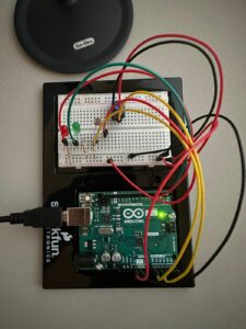
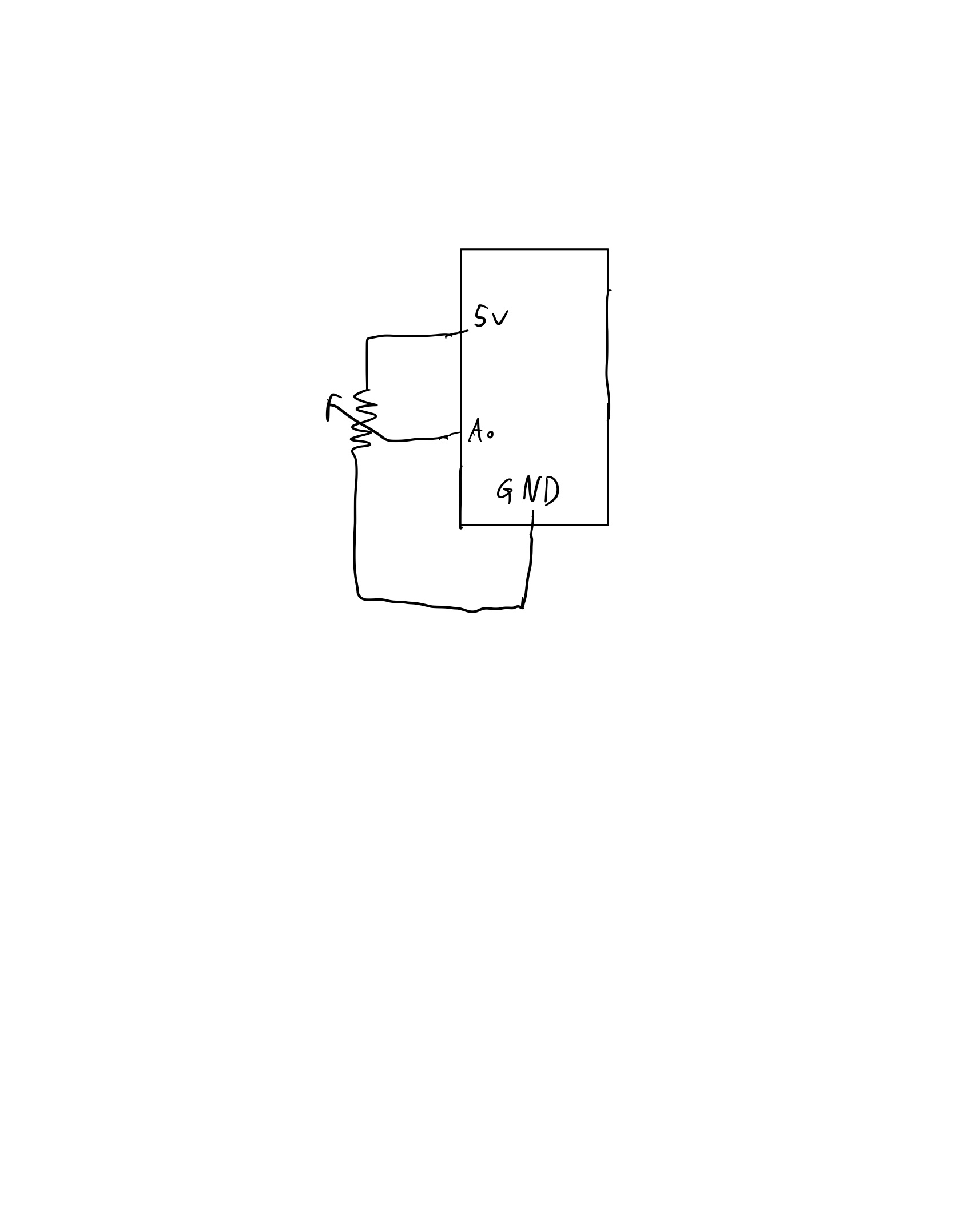
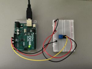
For this part, I made use of a potentiometer and connected it to the Arduino’s A0 port. The variable rVal changes according to the position of the potentiometer and this variable is in turn mapped to the ellipse’s x-position. I made the ellipse’s grey-scale value change according to the potentiometer’s reading.

Code
let rVal = 0;

function setup() {
  createCanvas(640, 480);
  textSize(18);
}

function draw() {
  // one value from Arduino controls the background's red color
  background(map(rVal, 0, 1023, 0, 255), 255, 255);

  if (!serialActive) {
    text("Press Space Bar to select Serial Port", 20, 30);
  } else {
    text("Connected", 20, 30);
    

    // Print the current values
    text('rVal = ' + str(rVal), 20, 50);
    text('alpha = ' + str(alpha), 20, 70);

  }
  
  // making an ellipse that moves according to the potentiometer's rVal 
  noStroke()
  fill(map(rVal, 0, 1023, 0, 255));
  ellipse(map(rVal, 0, 1023, 20, width - 20), height/2, 20);
}
Circuit


Prompt 2

Implementation & Challenges

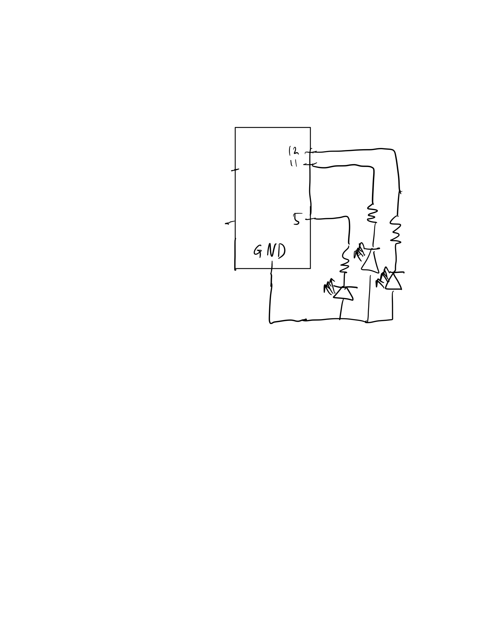
The prompt for the second task seemed straightforward initially: create a system to control LED brightness using p5. However, it turned out to be more challenging than expected. Our initial approach was to map the mouseX position relative to the screen width to adjust the brightness of the lamp accordingly. We removed the code for reading from p5 and writing to Arduino, as we thought only sending data from p5 was needed. However, we later realized that both read and write operations are necessary for establishing a connection.

Despite this realization, we still encountered issues as we didn’t initially understand that data must be continuously read and written from both Arduino and p5 for the circuit to function properly. It wasn’t just limited to the handshake phase, but required continuous data exchange. Despite the challenges, this exercise provided us with a deeper understanding of the serial connection between p5 and Arduino.

We also faced challenges with data formatting during the data exchange. It was important to ensure that the data sent from p5 was properly formatted with the addition of ‘\n’, and that Arduino used println instead of print to receive the data. This was crucial for establishing reliable communication between p5 and Arduino, and it required careful attention to detail to get the formatting right.

Code
p5Js
let rVal = 0;
let alpha = 255;
let left = 0;
let right = 0;
let brightness = 0;

function setup() {
  createCanvas(640, 480);
  textSize(18);
}

function draw() {
  // one value from Arduino controls the background's red color
  background(map(rVal, 0, 1023, 0, 255), 255, 255);

  // the other value controls the text's transparency value
  brightness = map(mouseX, 0, 640, 0, 255);

  if (!serialActive) {
    text("Press Space Bar to select Serial Port", 20, 30);
  } else {
    text("Connected", 20, 30);
    

    // Print the current values
    text('rVal = ' + str(rVal), 20, 50);
    text('alpha = ' + str(alpha), 20, 70);

  }

}

function keyPressed() {
  if (key == " ") {
    // important to have in order to start the serial connection!!
    setUpSerial();
  }
}


function readSerial(data) {
  ////////////////////////////////////
  //READ FROM ARDUINO HERE
  ////////////////////////////////////

  if (data != null) {

    //////////////////////////////////
    //SEND TO ARDUINO HERE (handshake)
    //////////////////////////////////
    let sendToArduino = brightness + "\n";
    writeSerial(sendToArduino);
  }
}
Arduino .ino
int leftLedPin = 2;
int rightLedPin = 5;

void setup() {
  // Start serial communication so we can send data
  // over the USB connection to our p5js sketch
  Serial.begin(9600);

  // We'll use the builtin LED as a status output.
  // We can't use the serial monitor since the serial connection is
  // used to communicate to p5js and only one application on the computer
  // can use a serial port at once.
  pinMode(LED_BUILTIN, OUTPUT);

  // Outputs on these pins
  pinMode(leftLedPin, OUTPUT);
  pinMode(rightLedPin, OUTPUT);

  // Blink them so we can check the wiring
  digitalWrite(leftLedPin, HIGH);
  digitalWrite(rightLedPin, HIGH);
  delay(200);
  digitalWrite(leftLedPin, LOW);
  digitalWrite(rightLedPin, LOW);

  // start the handshake
  while (Serial.available() <= 0) {
    digitalWrite(LED_BUILTIN, HIGH); // on/blink while waiting for serial data
    Serial.println("0"); // send a starting message
    delay(300);            // wait 1/3 second
    digitalWrite(LED_BUILTIN, LOW);
    delay(50);
  }
}

void loop() {
  // wait for data from p5 before doing something
  while (Serial.available()) {
    digitalWrite(LED_BUILTIN, HIGH); // led on while receiving data

    int right = Serial.parseInt();
    if (Serial.read() == '\n') {
      analogWrite(rightLedPin, right);
      int sensor = analogRead(A0);
      Serial.println(sensor);
    }
  }
  digitalWrite(LED_BUILTIN, LOW);
}

Prompt 3

Implementation & Challenges

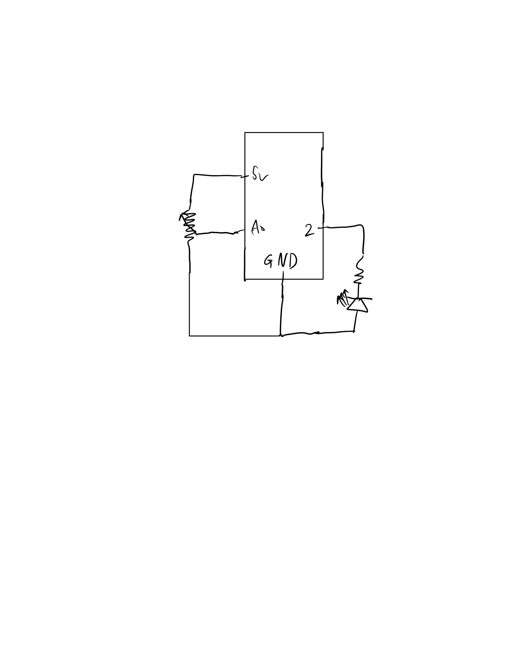
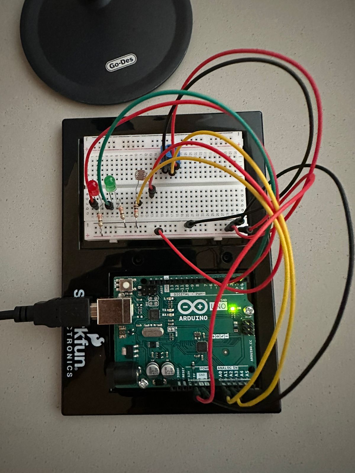
For the very last prompt, we were required to take an input from Arduino in the form of an Analog Sensor and also send data to Arduino to blink an LED.

Using an existing p5Js Sketch (https://editor.p5js.org/aaronsherwood/sketches/I7iQrNCul), the requirement was to blink the LED when the ball bounces, and use an Analog Sensor to control the wind.

Therefore, making use of the circuit we designed in class by taking help from the basics of these 3 sources, we began to adapt the Gravity Wind Example from p5Js:

      • Circuit (https://github.com/mangtronix/IntroductionToInteractiveMedia/blob/master/code/Week_11_Serial_schematic.png)
      • Arduino Code (https://github.com/mangtronix/IntroductionToInteractiveMedia/blob/master/code/Week11Serial.ino)
      • P5Js Starter Code (https://editor.p5js.org/mangtronix/sketches/s67XC0zT4)

The first task was to detect a bounce, and once a bounce was detected, we just simply sent a signal of ‘1’ to the Arduino – which only meant switching on the light, which would then switch off with ‘0’ being sent when the ball was in motion.

Similarly, the Potentiometer value was read from the Arduino, and its value was sent to the P5Js sketch. This value was checked to be either greater then 512, or less than that, which then meant left or right movement of the wind.

Video
Code
p5Js
let velocity;
let gravity;
let position;
let acceleration;
let wind;
let drag = 0.99;
let mass = 50;

let rVal = 0;
let alpha = 255;
let left = 0;
let right = 0;

function setup() {
  createCanvas(640, 360);
  noFill();
  position = createVector(width/2, 0);
  velocity = createVector(0,0);
  acceleration = createVector(0,0);
  gravity = createVector(0, 0.5*mass);
  wind = createVector(0,0);
}

function draw() {
  left = 0;
  background(255);
  applyForce(wind);
  applyForce(gravity);
  velocity.add(acceleration);
  velocity.mult(drag);
  position.add(velocity);
  acceleration.mult(0);
  fill(0);
  ellipse(position.x,position.y,mass,mass);
  if (position.y > height-mass/2) {
      velocity.y *= -0.9;  // A little dampening when hitting the bottom
      position.y = height-mass/2;
    }
  
  
  if(abs(velocity.y)>1){
    if(position.y+(mass/2)>=(height)){
      left = 1;
    }
  }
  
  // print(alpha);
  
  if(alpha>512){
    // print("right");
    wind.x=1;
  }
  else{
    // print("left");
    wind.x=-1;
  }
  

}

function applyForce(force){
  // Newton's 2nd law: F = M * A
  // or A = F / M
  let f = p5.Vector.div(force, mass);
  acceleration.add(f);
}

function keyPressed(){
  if (key == " ") {
    // important to have in order to start the serial connection!!
    setUpSerial();
  }
  
  if (keyCode==UP_ARROW){
    // wind.x=-1;
    position.y = 200;
  }
  
  if (keyCode==ENTER){
    mass=random(15,80);
    position.y=-mass;
    velocity.mult(0);
  }
}


function readSerial(data) {
  ////////////////////////////////////
  //READ FROM ARDUINO HERE
  ////////////////////////////////////

  if (data != null) {
    // make sure there is actually a message
    alpha = data;

    //////////////////////////////////
    //SEND TO ARDUINO HERE (handshake)
    //////////////////////////////////
    let sendToArduino = left + "\n";
    writeSerial(sendToArduino);
  }
}
Arduino .ino
// Week 11.2 Example of bidirectional serial communication

// Inputs:
// - A0 - sensor connected as voltage divider (e.g. potentiometer or light sensor)
// - A1 - sensor connected as voltage divider 
//
// Outputs:
// - 2 - LED
// - 5 - LED

int leftLedPin = 2;

void setup() {
  // Start serial communication so we can send data
  // over the USB connection to our p5js sketch
  Serial.begin(9600);

  // We'll use the builtin LED as a status output.
  // We can't use the serial monitor since the serial connection is
  // used to communicate to p5js and only one application on the computer
  // can use a serial port at once.
  pinMode(LED_BUILTIN, OUTPUT);

  // Outputs on these pins
  pinMode(leftLedPin, OUTPUT);

  // Blink them so we can check the wiring
  digitalWrite(leftLedPin, HIGH);
  delay(200);
  digitalWrite(leftLedPin, LOW);


  // start the handshake
  while (Serial.available() <= 0) {
    digitalWrite(LED_BUILTIN, HIGH); // on/blink while waiting for serial data
    Serial.println("0,0"); // send a starting message
    delay(300);            // wait 1/3 second
    digitalWrite(LED_BUILTIN, LOW);
    delay(50);
  }
}

void loop() {
  // wait for data from p5 before doing something
  while (Serial.available()) {
    digitalWrite(LED_BUILTIN, HIGH); // led on while receiving data

    int left = Serial.parseInt();
    // int right = Serial.parseInt();
    if (Serial.read() == '\n') {
      digitalWrite(leftLedPin, left); // Write value to the bulb, to blink it
      int sensor2 = analogRead(A1); // Read input from the Potentiometer
      delay(5);
      Serial.println(sensor2); // Send message to p5js
    }
  }
  digitalWrite(LED_BUILTIN, LOW);
}
Circuit


Final Project Proposal

Concept

Our project is to create a remote-controlled car that can be controlled using hand gestures, specifically by tracking the user’s hand position. We will achieve this by integrating a P5JS tracking system into the car, which will interpret the user’s hand gestures and translate them into commands that control the car’s movements.

Implementation

To implement this project, we will first build the remote-controlled car using an Arduino Uno board and other necessary components. We will then integrate the P5JS system, which will detect the user’s hand position and translate it into movement commands for the car. We have two options for detecting user’s hand position, either PoseNet or Teachable Machine.  The camera tracking system will be programmed to interpret specific hand gestures, such as moving the hand forward or backward to move the car in those directions.

Potential challenges

One potential challenge we may face during the implementation is accurately interpreting the user’s hand gestures. The camera tracking system may require experimentation and programming adjustments to ensure that it interprets the user’s hand movements accurately. Also testing will be required to see if PoseNet performs better or Teachable Machine. Responsiveness will also be a factor as we would want the control to be fluid for the user. Additionally, ensuring the car responds correctly to the interpreted movement commands may also present a challenge, in terms of the physical construction of the cars and the variability of the motors. 

Exercises + Final Project Idea

Homework Exercises


Ellipse Moving:

Switch + LED:

Arduino code:

// Week 11.2 Example of bidirectional serial communication

int analog_pin = A2;
int led_pin = 9;

void setup() {
  // Start serial communication so we can send data
  // over the USB connection to our p5js sketch
  Serial.begin(9600);

  pinMode(analog_pin, INPUT);
  pinMode(led_pin, OUTPUT);

  // start the handshake
  while (Serial.available() <= 0) {
    Serial.println("-1"); // send a starting message
    delay(300);            // wait 1/3 second
  }
}

void loop() {
  // wait for data from p5 before doing something
  while (Serial.available()) {
    int led_brightness = Serial.parseInt();
    digitalWrite(led_pin, led_brightness);

    Serial.println(map(analogRead(analog_pin), 0, 1023, -1, 1));
  }
}

P5.js code:

/* Week 11.2 bidi serial example
 * Originally by Aaron Sherwood
 * Modified by Mangtronix
 *
 * Add this library to Sketch files
 *  https://github.com/mangtronix/IntroductionToInteractiveMedia/blob/master/code/p5.web-serial.js files
 *
 * Arduino code:
 * https://github.com/mangtronix/IntroductionToInteractiveMedia/blob/master/code/Week11Serial.ino
 */

let dir = 0;
let x = 40;
let r = 40;
let inc = 2;

function setup() {
  createCanvas(640, 480);
}

function draw() {
  // one value from Arduino controls the background's red color
  background(0);

  ellipse(x,height/2,r*2,r*2);
  if (serialActive)
    x = dir == 1 ? min(width - r, x + inc) : x = max(r, x - inc);
  
}

function keyPressed() {
  if (key == " ") {
    // important to have in order to start the serial connection!!
    setUpSerial();
  }
}

// This function will be called by the web-serial library
// with each new *line* of data. The serial library reads
// the data until the newline and then gives it to us through
// this callback function
function readSerial(data) {
  ////////////////////////////////////
  //READ FROM ARDUINO HERE
  ////////////////////////////////////

  if (data != null) {
    // make sure there is actually a message
    // split the message
    let fromArduino = split(trim(data), "\n");

    // if the right length, then proceed
    if (fromArduino.length == 1) {
      // only store values here
      // do everything with those values in the main draw loop
      dir = fromArduino[0];
    }

    //////////////////////////////////
    //SEND TO ARDUINO HERE (handshake)
    //////////////////////////////////
    console.log("X: ", x);
    let output = map(x, r, width - r, 0, 255);
    console.log("Output: ", int(output));
    writeSerial(int(output));
  }
}


Gravity:

Arduino code:

// Week 11.2 Example of bidirectional serial communication

int analog_pin = A2;
int led_pin = 9;

void setup() {
  // Start serial communication so we can send data
  // over the USB connection to our p5js sketch
  Serial.begin(9600);

  pinMode(analog_pin, INPUT);
  pinMode(led_pin, OUTPUT);

  // start the handshake
  while (Serial.available() <= 0) {
    Serial.println("-1"); // send a starting message
    delay(300);            // wait 1/3 second
  }
}

void loop() {
  // wait for data from p5 before doing something
  while (Serial.available()) {
    int led_brightness = Serial.parseInt();
    digitalWrite(led_pin, led_brightness);

    Serial.println(map(analogRead(analog_pin), 0, 1023, -1, 1));
  }
}

P5.js code:

let velocity;
let gravity;
let position;
let acceleration;
let wind;
let drag = 0.99;
let mass = 50;
let led_on = 0;

function setup() {
  createCanvas(640, 360);
  noFill();
  position = createVector(width/2, 0);
  velocity = createVector(0,0);
  acceleration = createVector(0,0);
  gravity = createVector(0, 0.5*mass);
  wind = createVector(0,0);
}

function draw() {
  background(255);
  if (serialActive) {
    applyForce(wind);
    applyForce(gravity);
    velocity.add(acceleration);
    velocity.mult(drag);
    position.add(velocity);
    acceleration.mult(0);
    ellipse(position.x,position.y,mass,mass);
    if (position.y > height-mass/2) {
        led_on = 1;
        velocity.y *= -0.9; 
        position.y = height-mass/2;
    } else {
      led_on = 0;
    }
  }
}

function applyForce(force){
  // Newton's 2nd law: F = M * A
  // or A = F / M
  let f = p5.Vector.div(force, mass);
  acceleration.add(f);
}

function keyPressed(){
  if (keyCode==UP_ARROW){
    mass=random(15,80);
    position.y=-mass;
    velocity.mult(0);
  }
  if (key == " ") {
    setUpSerial();
  }
}

// This function will be called by the web-serial library
// with each new *line* of data. The serial library reads
// the data until the newline and then gives it to us through
// this callback function
function readSerial(data) {
  ////////////////////////////////////
  //READ FROM ARDUINO HERE
  ////////////////////////////////////

  if (data != null) {
    // make sure there is actually a message
    // split the message
    let fromArduino = split(trim(data), "\n");

    // if the right length, then proceed
    if (fromArduino.length == 1) {
      // only store values here
      // do everything with those values in the main draw loop
      wind.x = fromArduino[0];
    }

    //////////////////////////////////
    //SEND TO ARDUINO HERE (handshake)
    //////////////////////////////////
    console.log(led_on);
    writeSerial(led_on);
  }
}


Final Project

My plan for the Final Project is an interactive device for my room. It is going to have at least 2 buttons one for “Good Morning” and a second for “Good Night”. When pressed “Good Night”, Arduino will turn off the lights, and turn off the AC, while P5.js will wish me “Good Night”, and tell me what time my alarm is set for tomorrow and how much time is left, and something more(TBD). For the “Good Morning” button, Arduino will turn on the AC, while P5.js will greet me, tell me what’s on my calendar today, read me a motivational quote, and tell me how many emails and from whom I received while I was sleeping.

Most of this is very new for me and will be complicated but I believe that if APIs of external services will work properly on p5.js this project is very doable and I’m very optimistic about it. I will have to learn how to use Google Calendar API, Gmail API, and Text-to-Voice API.

The idea came from a “Jarvis” AI from the Iron Man movie. Just like Jarvis, my project will be able to control some aspects of my room and become my companion.