Week 10: Creative Instrument

Concept

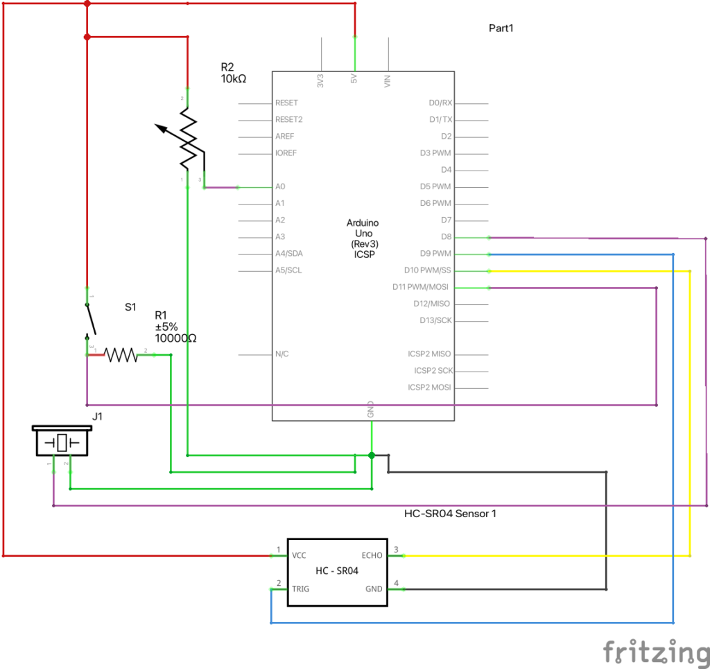
For this project, we decided on creating a creative musical instrument using a distance sensor. The device calculates the distance of an object (in this case, the object behaves as a percussion beater), and based on its location, tunes of varying frequencies are produced. The device allows the user to set the base note using a pushdown switch; once the switch is pressed, the distance calculated at that phase is used as an initial point. Thus, the user can move the beater to and fro in order to create a musical track. Similarly, using the potentiometer, the user can further control the duration and type of sound produced by the buzzer.

The devices used in the system are:

    • One ultrasonic distance sensor
    • One potentiometer
    • One piezo buzzer
    • One pushdown switch
    • One 10 000 ohm resistor

The design of the instrument is based on the schematics as shown below:

Codes

Our code mainly consists of 4 parts: ultrasonic sensor reading, button reading, potentiometer reading, and piezo buzzer output. We first started with ultrasonic sensors, referring to online code for simple distance measurement (Reference). We have slightly modified the original code to our needs.

int findDistance() 
{
  digitalWrite(trigPin, LOW);
  delayMicroseconds(2);

  // Sets the trigPin on HIGH state for 10 micro seconds
  digitalWrite(trigPin, HIGH);
  delayMicroseconds(10);
  digitalWrite(trigPin, LOW);

  // Reads the echoPin, returns the sound wave travel time in microseconds
  long duration = pulseIn(echoPin, HIGH);
  return (duration * 0.034 / 2);
}

This code above is a function that we used to measure distance using the ultrasonic sensor for each loop. Depending on the position of the object, the buzzer will produce different pitches of sound.

Then, the button comes in. Button is used to offset the starting position of the instrument. By placing an object in front of the sensor and pushing the button, the object’s position will automatically be set as a C4 note. Using this button, a player can adjust the instrument in a way that he or she is most comfortable with.

  if (millis() - currentTime > 200 || currentTime == 0) 
  {
    // If the switch is pressed, reset the offset
    if (digitalRead(11) == 1) 
    {
      distanceOffset = findDistance();
      Serial.print("new offset: ");
      Serial.println(distanceOffset);
      currentTime = millis();
    }
  }

  int distance = findDistance() - distanceOffset;

As shown above, when the button is pressed, the program will subtract the offset from the sensor reading.

int pitch_ = intoNotes(map(distance, 0, 20, 1, 7)); 

int pitch = pitch_ * myList[0];
int toneDuration = myList[1];

if(distance <= 20)
  {
    tone(pPin, pitch,toneDuration);                              // Controls 1. PinNumber, 2. Frequency, 3. Time Duration
  }
else
  {
    noTone(pPin);
  }

float intoNotes(int x)
{
  switch(x)
  {
    case 1:
      return 261.63;
    case 2:
      return 293.66;
    case 3:
      return 329.63;
    case 4:
      return 349.23;
    case 5:
      return 392.00;
    case 6:
      return 440.00;
    case 7:
      return 493.88;
    default:
      return 0;
  }
}

The code above is how a program produces different pitches depending on the distance. The program maps 20 cm into 7 different integers; depending on the value of the mapped value, intoNotes() will return a specific pitch value accordingly. If the distance is above 20cm, the instrument will simply not produce a sound.

The code consists of two more functionalities which is facilitated by the function titled “noteModifier()”. It is a void function that takes the data read from the potentiometer as an argument.

void noteModifier(int volt)
{
  float val1 = 0;

  if (volt > 4 && volt <= 4.6)
    val1 = 5;
  else if (volt > 3 && volt <= 4)
    val1 = 4;
  else if (volt > 2 && volt <= 3)
    val1 = 3;
  else if (volt > 1 && volt <= 2)
    val1 = 2;
  else
    val1 = 1;

  myList[0] = val1;
  myList[1] = val1 * 1000;
  
}


As a potentiometer is an analog sensor, it is connected to the A0 pin for a contiguous set of data that ranges from 0 to 1023. Before using this data as input, the values are mapped to a new scale of (1.0 to 5.0) V as the maximum emf in the circuit is 5V. The conversion is done by these lines of code at the beginning of the loop() function.

pVoltRead = analogRead(potentioPin);
trueVolt = (pVoltRead * 5.0/1023);
Serial.println(trueVolt);

Once the true volt in the potentiometer is calculated, the function noteModifier() uses a set of if-conditions to determine the value of a variable named ‘val1’. As seen in the code, the value of ‘val1’ varies based on the range of the true volt argument. The true purpose of using val1 is to alter the content of a global list “myList[]” declared at the beginning of the project. The list consists of two elements: (1) the first element is a coefficient that scales the frequency of the sound produced by the buzzer and (2) the second element is the duration of a single tone produced by the buzzer.

This way, the function determines two primary arguments — frequency and time duration — of the Arduino’s inbuilt function tone().

The idea here is to replicate the real-life application of the project. A user can rotate the knob in the potentiometer; consequently, different tones are produced for varying lengths of time. In short, including a potentiometer provides one additional layer of user interaction to the system. The second demo clip shows the functionality of the potentiometer and how it can be used to produce different tunes.

Reflection / Future Improvements

Working on this assignment was very entertaining and exciting. We were able to use different sensors in the kit and use them to create an object that we can physically interact with, unlike p5js. We believe the instrument came out as we initially expected, but there are a few points that we can improve upon:

      • Ultrasonic Sensor
        • Ultrasonic sensor uses sound waves to measure the distance. This means the measurement can be inaccurate and unreliable depending on the surface of the object the wave is hitting. Due to this, we found out our instrument malfunctions when trying to play it with our own hands. To improve this, we would like to use a laser distance sensor that is less affected by the object’s surface.
      • Piezo Buzzer
        • Piezo Buzzer is very simple to use, but its sound quality is great. If we use a better speaker, we may be able to add more interesting functionalities, such as producing different sounds of instruments when a button is pressed.

Watch demos of the instrument here:

Without potentiometer:

With potentiometer:

GitHub Link

Week 10: Musical Instrument

OVERVIEW

for this weeks musical instrument project, we created a DJ setup using servo motors and a piezo buzzer. A digital switch controls the piezo buzzer, which cycles through a series of melodies, while two potentiometers control the servo motors. The potentiometer on the left hand side controls the speed at which the arms rotate, while the potentiometer on the right hand side controls how wide the arm sweeps. A demo of the instrument is shown below. 

DESIGN 

Our original idea was that we wanted to create some type of percussion instrument that would play rhythms rather than notes,  since using the buzzers as the main focus of the instrument felt a bit predictable. Interestingly, the sound and movement of the servo motors reminded us of turn tables, and hence our DJ idea was born. We also really liked using potentiometers to control the rhythm of the servo motors, because the twisting motion of the potentiometers felt very intuitive and similar to the actual motion one would use on a turn table. To add more interest, we decided to add on a buzzer that would play “techno” music to make the entire piece have a clear “club” or “house” atmosphere. 

SCHEMATIC

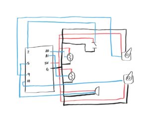
A schematic of our board is shown below:

CODE 

The instrument gets its input through two analog sensors – the potentiometers, and one digital sensor – the button. As mentioned above, the analog sensors control the servo motors, or the turn tables. Inside our program, the value obtained by the potentiometer is stored in a variables sensorValue1 and sensorValue2. The former is then used to control the delay, or how fast the motor arm is sweeping, while the latter controls the degree to which the arm motor sweeps. This is demonstrated in the code below:

for (pos1 = 0; pos1 <= 60 + sensorValue2/20; pos1 += 1) {
... 
    myservo1.write(pos1);              
    myservo2.write(pos1);
    delay(sensorValue1/50);    
}

On the other hand, the digital sensor controls which melody the piezo will play. Our program has an array of 3 different techno melodies (called melodies[], each 16 notes each. We cycle through each melody by defining a variable called melodyState, which ranges from 0-2, corresponding to the length of the melodies[] array, and increments each time the button is clicked. This is demonstrated in the following code:

In the beginning of loop() calculating the melodyState:

int buttonState1 = digitalRead(pushButton1);

 if (buttonState1==HIGH) {
   add = true; 
 }

if (add) {
   melodyState++;
   add=false;
 }
if (melodyState>=3) melodyState=0;

Using melodyState to index into the melodies[] array:

if (pos1%frequency==0) {
  tone(5, melody[melodyState][melodyCount], length);
  delay(50);
  noTone(5);

  melodyCount++;
  if (melodyCount >=16) { 
    melodyCount = 0; 
  }

CHALLENGES  & IMPROVEMENTS

One of the challenges of this project was the wiring. Because we had so many elements we wanted to incorporate, we did struggle with the circuit getting cut off in certain places where we added new elements. Also, because we used two potentiometers, and one of them was directly connected to 5V, and all other elements were connected to this potentiometer, this meant that when it was turned all the way down, all the power was shut off and the circuit broke. In terms of what we would like to improve, we thought it would be cool to add lights that would flash in correspondence with the melody that was playing, though because our board was already very cluttered, we opted against it. (As shown in the demo, it is a little difficult to maneuver given the tight space). We do, however, think it is worth experimenting with spreading our circuit across multiple breadboards. For example, it would be nice to have the servo motors and potentiometers on one board, and the buzzer and lights on another.  

Musical Instrument

OVERVIEW

for this weeks musical instrument project, we created a DJ setup using servo motors and a piezo buzzer. A digital switch controls the piezo buzzer, which cycles through a series of melodies, while two potentiometers control the servo motors. The potentiometer on the left hand side controls the speed at which the arms rotate, while the potentiometer on the right hand side controls how wide the arm sweeps. A demo of the instrument is shown below. 

DESIGN 

Our original idea was that we wanted to create some type of percussion instrument that would play rhythms rather than notes,  since using the buzzers as the main focus of the instrument felt a bit predictable. Interestingly, the sound and movement of the servo motors reminded us of turn tables, and hence our DJ idea was born. We also really liked using potentiometers to control the rhythm of the servo motors, because the twisting motion of the potentiometers felt very intuitive and similar to the actual motion one would use on a turn table. To add more interest, we decided to add on a buzzer that would play “techno” music to make the entire piece have a clear “club” or “house” atmosphere. 

SCHEMATIC

A schematic of our board is shown below:

CODE 

The instrument gets its input through two analog sensors – the potentiometers, and one digital sensor – the button. As mentioned above, the analog sensors control the servo motors, or the turn tables. Inside our program, the value obtained by the potentiometer is stored in a variables sensorValue1 and sensorValue2. The former is then used to control the delay, or how fast the motor arm is sweeping, while the latter controls the degree to which the arm motor sweeps. This is demonstrated in the code below:

for (pos1 = 0; pos1 <= 60 + sensorValue2/20; pos1 += 1) {
... 
    myservo1.write(pos1);              
    myservo2.write(pos1);
    delay(sensorValue1/50);    
}

On the other hand, the digital sensor controls which melody the piezo will play. Our program has an array of 3 different techno melodies (called melodies[], each 16 notes each. We cycle through each melody by defining a variable called melodyState, which ranges from 0-2, corresponding to the length of the melodies[] array, and increments each time the button is clicked. This is demonstrated in the following code:

In the beginning of loop() calculating the melodyState:

int buttonState1 = digitalRead(pushButton1);

 if (buttonState1==HIGH) {
   add = true; 
 }

 if (add) {
   melodyState++;
   add=false;
 }
if (melodyState>=3) melodyState=0;

Using melodyState to index into the melodies[] array:

if (pos1%frequency==0) {
  tone(5, melody[melodyState][melodyCount], length);
  delay(50);
  noTone(5);

  melodyCount++;
  if (melodyCount >=16) { 
    melodyCount = 0; 
  }

CHALLENGES  & IMPROVEMENTS

One of the challenges of this project was the wiring. Because we had so many elements we wanted to incorporate, we did struggle with the circuit getting cut off in certain places where we added new elements. Also, because we used two potentiometers, and one of them was directly connected to 5V, and all other elements were connected to this potentiometer, this meant that when it was turned all the way down, all the power was shut off and the circuit broke. In terms of what we would like to improve, we thought it would be cool to add lights that would flash in correspondence with the melody that was playing, though because our board was already very cluttered, we opted against it. (As shown in the demo, it is a little difficult to maneuver given the tight space). We do, however, think it is worth experimenting with spreading our circuit across multiple breadboards. For example, it would be nice to have the servo motors and potentiometers on one board, and the buzzer and lights on another.  

Week 9: Traffic light controller

Concept

For this assignment, I decided to make a traffic light that can be controlled by the enemy and get broken. It gets broken by using the potentiometer, which turns it off or turns all the lights on at the same time which can create a huge traffic jam. However, policemen can make it work by clicking the button, which lets the lights turn on one by one.

Code

int potpin = 2;  // analog pin used to connect the potentiometer
int val; 
void setup() {
  pinMode(7, OUTPUT);
  pinMode(2, OUTPUT);
  pinMode(4, OUTPUT);
  pinMode(A2, INPUT);
}

void loop() {

  int switchPosition = digitalRead(A2);
  val = analogRead(potpin);            // reads the value of the potentiometer (value between 0 and 1023)
  val = map(val, 0, 1023, 0, 360); 
  if (switchPosition == LOW) {
    digitalWrite(4, val);   
    digitalWrite(2, val);
    digitalWrite(7, val);


  } else  {

    digitalWrite(7, HIGH);    // turn the  red LED on
    digitalWrite(4, LOW);
    digitalWrite(2, LOW);
    delay(500);
    digitalWrite(7, LOW);    // turn the yellow LED on
    digitalWrite(4, HIGH);
    digitalWrite(2, LOW);
    delay(500);
    digitalWrite(7, LOW);    // turn the green LED on
    digitalWrite(4, LOW);
    digitalWrite(2, HIGH);
    delay(500);
    digitalWrite(4, HIGH);   // turn all the lights on
    digitalWrite(2, HIGH);
    digitalWrite(7, HIGH);
  }
}

Reflection

Connecting several lights and making them light one by one was a really fun exercise. However, adding a potentiometer broke down my switch at some point, which made it difficult for me to control the LED light using it. For future improvements, I would like to be able to have different outputs when changing the potentiometer values when the switch is on and off, so the game mode can get difficult, so I can learn more about the potentiometer’s advanced features.

Week 9: Analog and Digital sensors – Picture Perfect

Concept

I have always wondered why it is not possible to take the perfect picture of yourself. I realized that two of the most important controllable variables in photography are the lighting and the focus distance. Hence the project was designed to give an indication of the perfect lighting for the surroundings and the distance for the person taking the photo.

Implementation

const int buttonPin = 7; 
int onOff = 0;
int sensorPin = A0;   
int ledPin = 13;  
int sensorValue = 0; 
const int blueLEDPin = 12;
const int yellowLEDPin = 8;
const int goLED = 10;
#define echoPin 2 
#define trigPin 3
long duration; 
int distance;
void setup() {
  // put your setup code here, to run once:
  
  pinMode(ledPin, OUTPUT);
  digitalWrite(blueLEDPin, OUTPUT);
  digitalWrite(yellowLEDPin, OUTPUT);
  digitalWrite(goLED, OUTPUT);
  pinMode(buttonPin, INPUT);
  Serial.begin(9600);

  //Ultra
  pinMode(trigPin, OUTPUT); // Sets the trigPin as an OUTPUT
  pinMode(echoPin, INPUT); // Sets the echoPin as an INPUT

}

void loop() {
  onOff = digitalRead(buttonPin);
//LDR
  sensorValue = analogRead(A0);
  Serial.println(sensorValue);
  digitalWrite(ledPin, LOW);
  digitalWrite(blueLEDPin, LOW);
  delay(sensorValue/2);
  digitalWrite(ledPin, HIGH);
  digitalWrite(blueLEDPin, HIGH);
  delay(sensorValue/2);

  //Ultrasonic sensor
  digitalWrite(trigPin, LOW);
  delay(2);
  digitalWrite(trigPin, HIGH);
  delay(10);
  digitalWrite(trigPin, LOW);
  duration = pulseIn(echoPin, HIGH);
  distance = duration * 0.034 / 2; 
  Serial.print("Distance: ");
  Serial.print(distance);
  Serial.println(" cm");

  if ((distance>40&&distance<55)){
    digitalWrite(yellowLEDPin, HIGH);
    
  }
  else {
    digitalWrite(yellowLEDPin, LOW);
    delay(distance*2);
    digitalWrite(yellowLEDPin, HIGH);
  }
  Serial.println(onOff);
  if ((distance>40&&distance<55)&&(sensorValue>600 &&sensorValue<900)&&(onOff == LOW)){
    digitalWrite(goLED, HIGH);
    digitalWrite(yellowLEDPin, HIGH);
    digitalWrite(blueLEDPin, HIGH);
    delay(10000);
    digitalWrite(goLED, LOW);
    digitalWrite(yellowLEDPin, LOW);
    digitalWrite(blueLEDPin, LOW);
  
  }

}

The program takes in the lighting of the surroundings using the LDR and then makes the blue LED turn on and off proportional to the intensity of the light. This shows if you need to increase the light in surroundings or if it getting closer to the perfect level. Likewise with the Ultrasonic sensor, it detects the distance from the object right in front and inputs distance data and the yellow led blinks proportionally to the distance from sensor. When button is pressed and conditions are met, the lights stay on for 10 seconds.

Reflections

Initially, I wanted to use Tarek’s creative switch idea to make sure that the subject is flexing for the picture. However, I realized that it would require a considerable length of wire to obtain a reasonable distance to take a good picture. I also wanted to make the iPhone take the photo itself via voice commands (where a recoding of me sating “hi Siri, take a picture” would be output once the correct conditions are met). However, iOS security regulations and the lack of complexity in the speaker would not allow this function.

Using Sensors To Control LED Output

Concept:

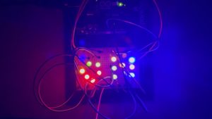
My idea was to use the photoresistor as an analog sensor to control how a group of LEDs display. With a decrease in resistance as a result of lumen capacity, the photoresistor controls the LEDs to output a pattern of light displays which spells “ON”. Whereas with high resistance due to less lumen capacity, the LEDs output in a pattern which spells “OFF” with a missing F due to space.

The change between “ON” and “OFF” is controlled by two LEDs which read the analog value of the photoresistor and output a scaled down value of it.

The code:


int g1 = 12;
int g2 = 11;
int fOn = 8;
int fOff = 7;
int sens = A0;
int sensVal;
int ledval;

void setup() {
  // put your setup code here, to run once:
  pinMode(g1, OUTPUT);
  pinMode(g2, OUTPUT);
  pinMode(A0, INPUT);
  Serial.begin(9600);
}

void loop() {
  // put your main code here, to run repeatedly:
  sensVal = analogRead(sens);
  ledval = (255./1023.) * sensVal;
  Serial.println(sensVal);
  delay(250);
  if(sensVal < 200){
    digitalWrite(g1, HIGH);
    digitalWrite(g2, HIGH);
    analogWrite(fOn, ledval);
    digitalWrite(fOff, LOW);
  }
  else{
    digitalWrite(g1, HIGH);
    digitalWrite(g2, HIGH);
    analogWrite(fOff, ledval);
    digitalWrite(fOn, LOW);
  }
  
}

The “ON” state display:

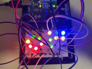
The “OFF” state display:


When the lights are on the leds display on and when the lights are off the leds display off.

The video demonstration:


Reflections:

It was challenging to set up the LEDs group them together to display. With a little try and error and schematic, I got them to work. I plan to add sound and other output signals to signify when the lights are out.


My attempt at adding sound:

Week 9: Analog & digital sensors

Concept

For this assignment we were required to get information from at least one analog sensor and at least one digital sensor (switch), and use this information to control at least two LEDs, one in a digital fashion and the other in an analog fashion, in some creative way. At first I thought of doing a distance-related project using the ultrasonic sensor, but I decided to stick to my previous project on moisture detection to try and make it better. So for this assignment I incorporated a digital sensor (switch) and more LEDs for different scenarios.

Code

The coding aspect of the implementation was a bit challenging as it involved a lot of trial, observation and error.  A snippet of the code below shows how the LEDs change color based on amount of moisture detected.

void loop() {
  int low = 350, high = 100, water, pepsi;
  bool status = false;
  int sensorValue = analogRead(A0);
  if(digitalRead(7)==1)
    { digitalWrite(6, HIGH);
    if(sensorValue < 550)
     digitalWrite(5, HIGH);
    else
     digitalWrite(5, LOW);
   if(sensorValue > 550)
     digitalWrite(4, HIGH);
   else
     digitalWrite(4, LOW);}

Result / Future improvements

The original idea was to create a demo of an instrument that can measure moisture of say the area where a tree should be planted. If the there isn’t enough moisture the yellow LED turns on indicating that the area is dry. If there is optimal moisture levels for the tree to be planted then the green LED turns on. The blue LED is controlled by the digital sensor to allow electricity to pass and flow throughout the circuit. In the video below, the green towel has been moisturized with water and the orange one is the dry one. The original idea was to implement the digital switch as a toggle switch, which when clicked stays on until clicked again. However, this proved to be very complicated and couldn’t implement it in the end.

Analog and Digital Sensor

Concept

I TRIED to make a circuit in which an LED could be powered on or off by a switch (button) and a photoresistor (light sensor). When you press the button, you can switch the LED on or off. When the LED is off, however, you can either switch it on by clicking the button, or by waving your hand or any other object on top of the photoresistor to cover it. This is because when the photoresistor is not exposed to much light, it can trigger the LED to switch on.

I followed a tutorial by Electronic Explorer on YouTube in order to figure out the photoresistor’s circuit configuration as well as the coding required to go with it.

To add the button to the circuit, I placed two green wires on either side that connected the button to the rest of the circuit.

  • The problem with this, however, was that when I connected the button to the circuit, the photoresistor could no longer control the LED. The only way it could switch it on is by clicking the button.

I came up with another way to fix this, but I had to completely remove the button and keep the two wire ends that were connected to it exposed. This way, I could switch on the LED by either:

  • Waving my hands over the photoresistor

OR

  • Connecting the two exposed wires to each other to close the circuit

Video

Here’s a video of my brother showing you how to use it:

Code

int LDR = 0;
void setup() {
  pinMode(13, OUTPUT);
  pinMode(A0, INPUT);
  Serial.begin(9600);
}

void loop() {
  LDR = analogRead(A0);
  Serial.println(LDR);
  if(LDR < 512)
  {
    digitalWrite(13, 1);
  }
  else
  {
    digitalWrite(13, 0);
  }

}

Reflection and Improvements:

  • I couldn’t figure out how to embed coding for the button (switch) so that the LED could either turn on from the button being pressed or the photoresistor being covered.
  • I want to learn how to code proficiently on Arduino because I didn’t know how to resolve any of the problems I had when trying to adjust something in the circuit.
  • I also wish I could’ve implemented more creativity overall (especially for the button which I couldn’t figure out how to connect).

Week 9: Analog and Digital Sensor

Concept:

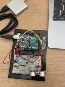
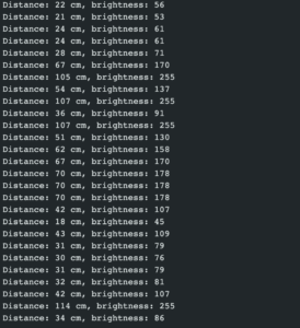
To construct this project, I had to learn how to use the ultrasonic sensor online, which measures the distance between the sensor and an item in front of it by sending signals and calculating the time it takes for it to return. I set up the ultrasonic sensor but I wanted to control the brightness of an LED lamp by the distance measured by it. Hence, I made the scale of the brightness of the lamb range between 0 cm away from the ultrasonic sensor and 100 cm (1m). 1m(and beyond) being the brightest and 0 being the dullest. To achieve this, I had to multiply the distance measured by the ultrasonic sensor by 2.55; if the distance is more than 100 cms, it tunes it down to 255.

Afterward, I wanted to activate the ultrasonic sensor only when a button is pressed while acknowledging the user that the ultrasonic sensor. Therefore I made two LEDs dependent upon the button that blinks for around 2 seconds, while the ultrasonic sensor takes the input and alters the brightness of the LED bulb that is dependent upon the distance.

Code:

At the beginning of the code, the global variables are initialized with the duration it takes the ultrasonic takes back the variable distance to store it in. with the pins the echo and the trig are connected to.

The LEDS are connected to dynamic or analog pins according to their usage. as well as one pin to check if the button is pressed.

int buttonPin = A0;
int redLed = 2;
int blueLed = 4;

int greenLed = 6;

int echo = 11;
int trig = 10;

long duration;
long distance;

In setup, the pins for the leds and ultrasonic are set up as well as the Serial to know the distance exactly and the brightness of the main LED.

void setup() {
  // setup pin modes
  Serial.begin(9600);
  pinMode(redLed, OUTPUT);
  pinMode(blueLed, OUTPUT);

  pinMode(trig, OUTPUT); 
  pinMode(echo, INPUT);
}

In the loop function, the program continuously checks if the button is pressed, and if it is pressed it calls the function blink.

void loop() {
  digitalWrite(trig, LOW);
  delayMicroseconds(2);

  int buttonState = digitalRead(buttonPin);
  if(buttonState == HIGH){
    blink(2);
  }
}

The blink function makes the red and blue LEDs blink while calling a function to make the ultrasonic sensor start getting data and alter the brightness of the green LED.

void blink(int period){
  period = period * 5;
  for(int i = 0; i < period; i++){
    digitalWrite(redLed, LOW);
    digitalWrite(blueLed, HIGH);
    delay(100);
    digitalWrite(redLed, HIGH);
    digitalWrite(blueLed, LOW);
    delay(100);
    updateSensor();
  }
  digitalWrite(redLed, LOW);
  digitalWrite(blueLed, LOW);

}

The update sensor function gets data for the ultrasonic sensor by getting the time difference it takes for the ultrasonic waves to go out and come back, and by this data calculates the distance. then transforms the distance to a number that can be converted to an analog brightness.

void updateSensor(){
  digitalWrite(trig, HIGH);
  delayMicroseconds(10);
  digitalWrite(trig, LOW);
  duration = pulseIn(echo, HIGH);
  distance = duration * 0.034 / 2; 

  int brightness = ((int)(distance * 2.55) );
  brightness = (brightness > 255)? 255 : brightness;

  Serial.print("Distance: ");
  Serial.print(distance);
  Serial.print(" cm, ");
  Serial.print("brightness: ");
  Serial.println(brightness);


  analogWrite(greenLed,brightness);
}


Reflection:

In this project, to be honest I achieved everything I was looking for. However, I was thinking about alerting the user while the ultrasonic sensor is running by a speaker and making the program start in another more interactive way than a button like a sound command recognition. I am not sure how can that be possible since it’s complex and needs AI, but if it’s manageable I am looking forward to working on a project like that.

In my project, the distance is changing is the brightness of the LED lamp. I was thinking about making it change to something more interactive like the speed of a motor.


Assignment 9- The Color Palette

For this assignment, I started off by placing an LED and playing with the switch to control its blinking parameter. Gradually, I added two more LEDs to the circuit. And controlled them alternatively when the switch was switched on and off. After playing with it for a while, I decided to give it a whimsy twist to highlight the process of how we make secondary colors on the color palette when two primary colors get mixed. Hence, when a blue “colored” LED is mixed with a yellow “colored” LED, we get the green “color” or in other words, the switch controls the primary colors (blue and yellow) and the potentiometer creates the secondary color (green).

CODE AND CHALLENGES

It took me quite some time to figure out how three LEDs had to be controlled using a single switch in the code and then to alternate their blinking movements too. Initially, the three LEDs in the series were not switching on and off so I had to change the input value to INPUT_PULLUP.

int switchPin = 5;
 int led1Pin = 6;
 int led2Pin = 7;
 int led3Pin = 8;
 

void setup()
{
  pinMode(led1Pin, OUTPUT);
  pinMode(led2Pin, OUTPUT);
  pinMode(led3Pin, OUTPUT);
  pinMode(switchPin, INPUT_PULLUP);
  
}
void loop()
{
  byte buttonState = digitalRead(switchPin);
  
  if (buttonState == LOW) {
    digitalWrite(led1Pin, HIGH);
    digitalWrite(led2Pin, LOW);
    digitalWrite(led3Pin, HIGH);
  }
  else if (buttonState != LOW){
    digitalWrite(led1Pin, LOW);
    digitalWrite(led2Pin, HIGH);
    digitalWrite(led3Pin, LOW);
}
}

Secondly, connecting the potentiometer to control the green LED’s brightness through an analog input was a task too. It was either the switch or the potentiometer that was controlling the LEDs, I had to code them in the same button state if-else conditional to get them to work together.

else if (buttonState == LOW) {
//     int prValue = analogRead(Pr);
//     int brightness = map(prValue, 0, 1023, 0, 255);
//     analogWrite(led3Pin, brightness);    
//   }

Here is the artist session!

REFLECTIONS

Since I coded in C++ for the first time, I had to go through multiple tutorials to finalize my code. I am happy with the final outcome but would also like to further experiment with analog and sensor switches separately before putting them together. The animation is still very simple, but I would also like to work a bit more on them for example make the first LED blink once, the second LED twice, and so on. I did try to incorporate these cases in my project through delay() but was not able to do so while connecting both sensory and analog switches.