Concept
For my final project, I made a radio that changes FM channels according to what value range you turn the potentiometer dial to. I inputted song files that play according to their designated serial monitor value and an array of different songs for each channel.
This includes:
- 51-240 (Hip Hop), which is designated the variable RED on p5
- 241-429 (History), variable YELLOW on p5
- 430-619 (Classic Rock), variable GREEN on p5
- 620-814 (Classical), variable TEAL on p5
- 815-1023 (Khaleeji), variable BLUE on p5
For 0-50 Radio is switched off (variable OFF on p5)
Implementation and Interaction
So, whenever you turn the dial to 267, for example, an audio file from the History channel will start to play, and the yellow LED will simultaneously light up to indicate the change in channels.
The interactive element comes from you turning the dial to change the channel, and being able to control the output according to what value you stop on.
Arduino Code
int potPin = A5; // potentiometer
int bluePin = 2;
int tealPin = 3;
int greenPin = 4;
int yellowPin = 5;
int redPin = 6;
int currentColor = 0; // current color
int OFF = 0;
int RED = 6;
int YELLOW = 5;
int GREEN = 4;
int TEAL = 3;
int BLUE = 2;

void setup() {
  pinMode (potPin, INPUT);
  pinMode (bluePin, OUTPUT);
  pinMode (tealPin, OUTPUT);
  pinMode (greenPin, OUTPUT);
  pinMode (yellowPin, OUTPUT);
  pinMode (redPin, OUTPUT);
  Serial.begin (9600); // serial monitor count
}

void loop() {

  // x == y (x is equal to y)
  // x != y (x is not equal to y)
  // x <  y (x is less than y)
  // x >  y (x is greater than y)
  // x <= y (x is less than or equal to y)
  // x >= y (x is greater than or equal to y)

  delay(100);
  int potMeasure = analogRead (A5);
  int mappedPot = map(potMeasure, 0, 1023, 0, 255);
  Serial.println(currentColor);

  if ((potMeasure > 0) && (potMeasure <= 50)) {
    currentColor = 0;
    digitalWrite (redPin, LOW);
    digitalWrite (yellowPin, LOW);
    digitalWrite (greenPin, LOW);
    digitalWrite (tealPin, LOW);
    digitalWrite (bluePin, LOW);
    int OFF = 0;
  }
  else if ((potMeasure > 50) && (potMeasure <= 240)) {
    currentColor = 6;
    digitalWrite (redPin, HIGH);
    digitalWrite (yellowPin, LOW);
    digitalWrite (greenPin, LOW);
    digitalWrite (tealPin, LOW);
    digitalWrite (bluePin, LOW);
    int RED = 1;
  }
  else if ((potMeasure > 240) && (potMeasure < 430)) {
    currentColor = 5;
    digitalWrite (yellowPin, HIGH);
    digitalWrite (redPin, LOW);
    digitalWrite (greenPin, LOW);
    digitalWrite (tealPin, LOW);
    digitalWrite (bluePin, LOW);
    int YELLOW = 2;
  }
  else if ((potMeasure >= 430) && (potMeasure < 620)) {
    currentColor = 4;
    digitalWrite (greenPin, HIGH);
    digitalWrite (redPin, LOW);
    digitalWrite (yellowPin, LOW);
    digitalWrite (tealPin, LOW);
    digitalWrite (bluePin, LOW);
    int GREEN = 3;
  }
  else if ((potMeasure >= 620) && (potMeasure < 815)) {
    currentColor = 3;
    digitalWrite (tealPin, HIGH);
    digitalWrite (redPin, LOW);
    digitalWrite (yellowPin, LOW);
    digitalWrite (greenPin, LOW);
    digitalWrite (bluePin, LOW);
    int TEAL = 4;
  }

  else if ((potMeasure >= 815) && (potMeasure <= 1023)) {
    currentColor = 2;
    digitalWrite (bluePin, HIGH);
    digitalWrite (redPin, LOW);
    digitalWrite (yellowPin, LOW);
    digitalWrite (greenPin, LOW);
    digitalWrite (tealPin, LOW);
    int BLUE = 5;
  }
}
For my Arduino code, I essentially made it so that whenever the integer potMeasure (potentiometer value) is between a range of values, it would trigger the designated pin to light up.
For example, this segment of code here shows that whenever the potMeasure value is between or equivalent to 817 and 1023, all other pins but the bluePin are on LOW (to indicate them being switched off), and the bluePin is on HIGH (to indicate it being switched on). Each colored pin stands for each colored LED on the board.
else if ((potMeasure >= 817) && (potMeasure <= 1023)) {
currentColor = 2;
digitalWrite (bluePin, HIGH);
digitalWrite (redPin, LOW);
digitalWrite (yellowPin, LOW);
digitalWrite (greenPin, LOW);
digitalWrite (tealPin, LOW);
int BLUE = 5;
}
The currentColor integer encompasses each of the potMeasure ranges for each LED to light up, hence why if the serial monitor is between or equivalent to 815 and 1023, the value 2 would pop up as it is the designated value for the blue LED.
int potMeasure = analogRead (A5);
int mappedPot = map(potMeasure, 0, 1023, 0, 255);
Serial.println(currentColor);
p5 Code
For p5, I first uploaded all the audio files for each channel to function preload and designated each channel an array of audio files that p5 can randomly choose from.
soundFormats("mp3");
 // BLUE (KHALEEJI)
blueSong1 = loadSound ("MEHAD.mp3");
blueSong2 = loadSound ("UMY KM AHWAHA.mp3")
blueSounds = [blueSong1, blueSong2] // etc
I then designated a new variable called oldData in function draw, which holds the previous value of inData (serial monitor value/ potMeasure on Arduino). This was done so that whenever the user changes the channel, p5 would stop the song from playing so as to not interrupt the next song.
// oldData holds the *previous* value of inData

// if user changes station, p5 checks that oldData has changed into inData
// then prints the change
if (inData != oldData) {
  // The station changed
   console.log("changed from " + oldData + " to " + inData);

  // stops all songs if inData (new station value) is not equal to oldData (old station value)
  redSong1.stop();
  redSong2.stop();
  yellowSong1.stop();
  yellowSong2.stop();
  greenSong1.stop();
  tealSong1.stop();
  blueSong1.stop();
  blueSong2.stop();
I then created an if statement for each inData value (BLUE in this context is the Khaleeji channel. Within each statement, there would be a new variable initializing the random selection of songs from the designated array, which it would then play.
if (inData == BLUE){
  khaleejiChannel = random(blueSounds)
  khaleejiChannel.play()
}
I then added more if statements further below within function draw, which consisted of the font and text to be displayed on the screen every time a channel is changed.
else if (inData == BLUE) { // KHALEEJI

    // CHANNEL NAME TEXT
    noStroke();
    fill (128,172,57); // text color
    textFont(radioFont, 45); // (font name, font size)
    text("KHALEEJI", 178, 148); // (text, x, y)
    glow(color(128,172,57), 19); // (color, intensity) calls glow function

  }
The glow variable refers to the glow function further below, which makes the text look like it’s lit up.
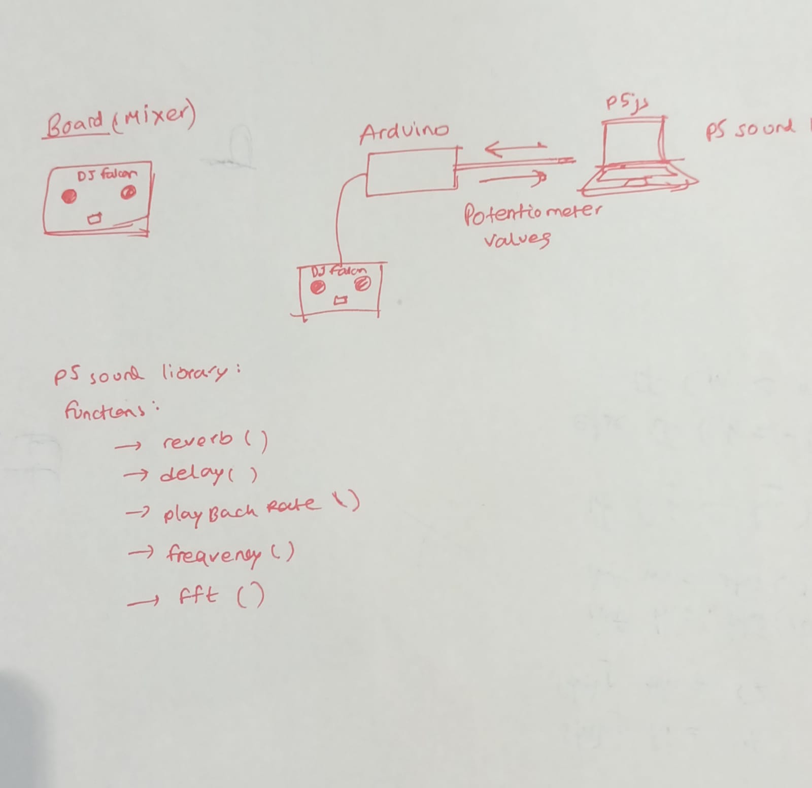
Audiovisual Communication between Arduino and p5
Arduino and p5 input:
- Potentiometer values
Arduino output (visual):
- LEDs lighting up
p5 output (audio):
- Songs being played
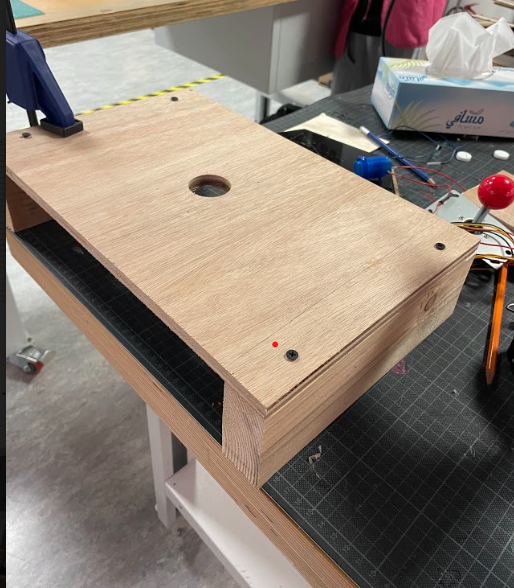
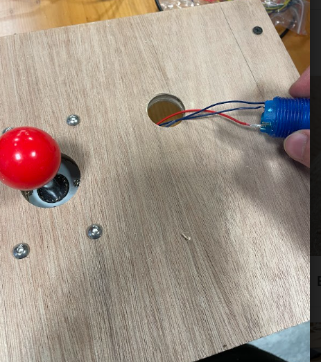
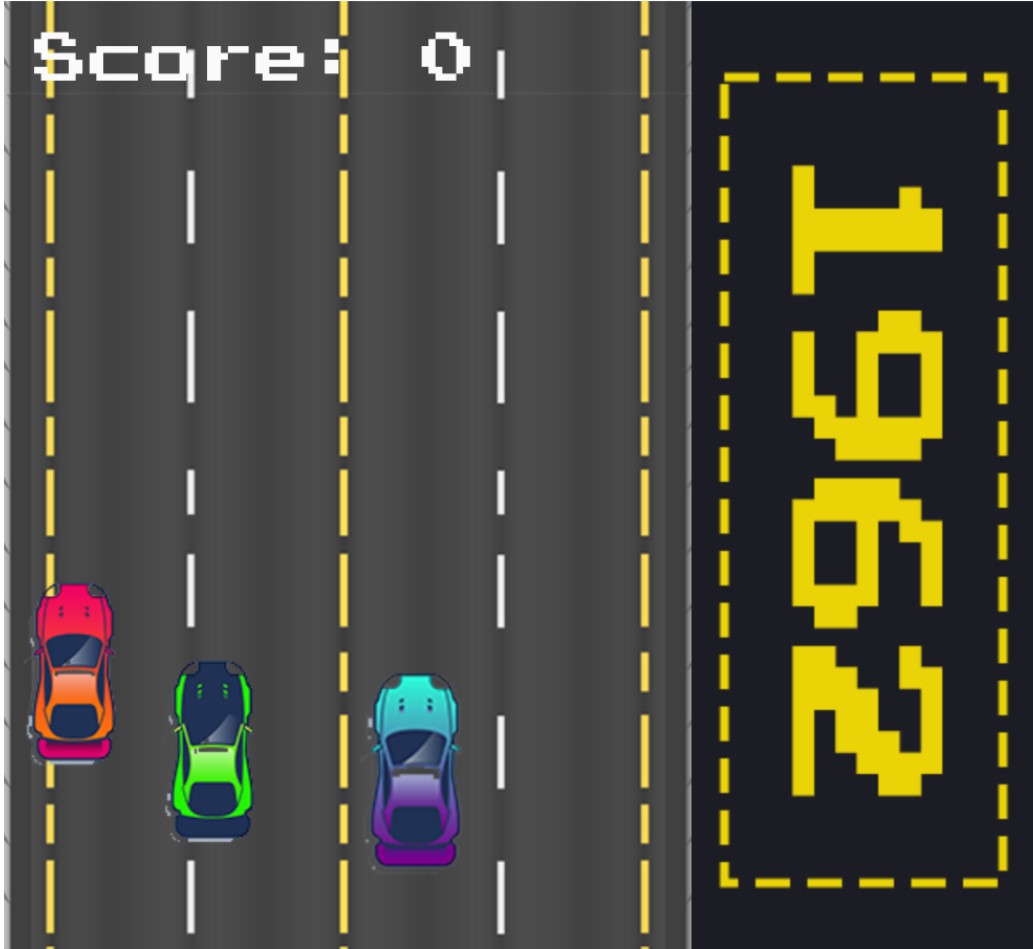
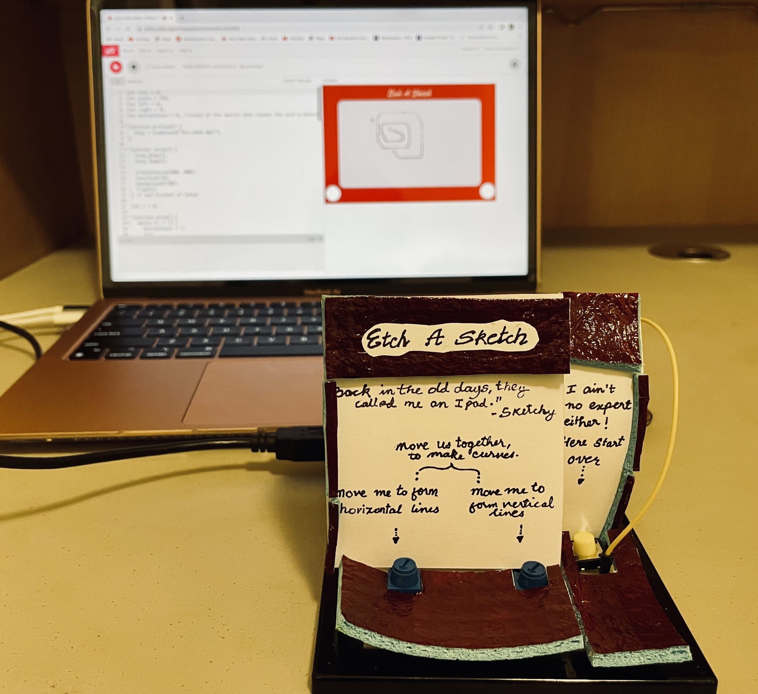
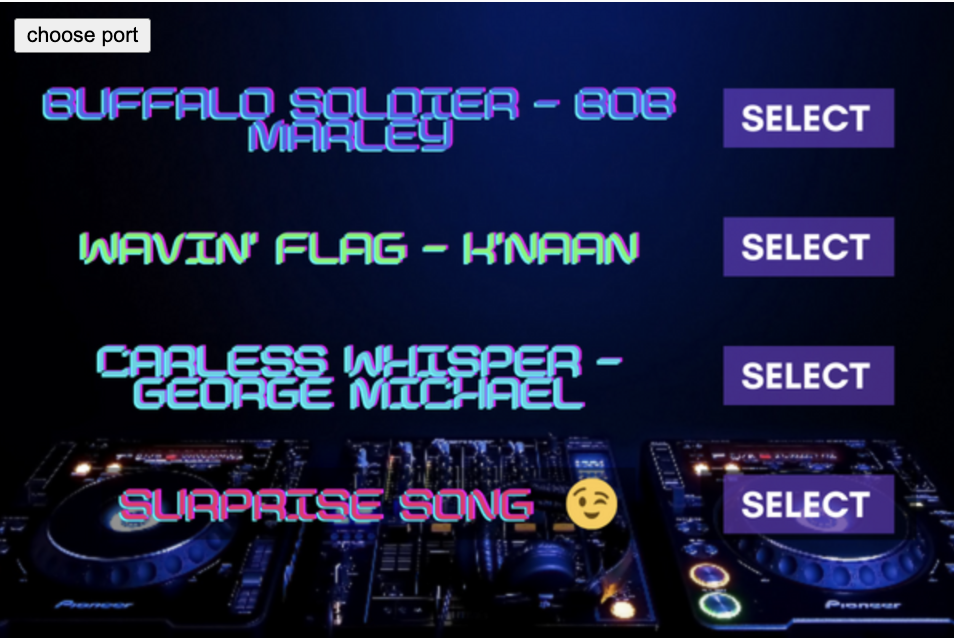
p5 Screen Design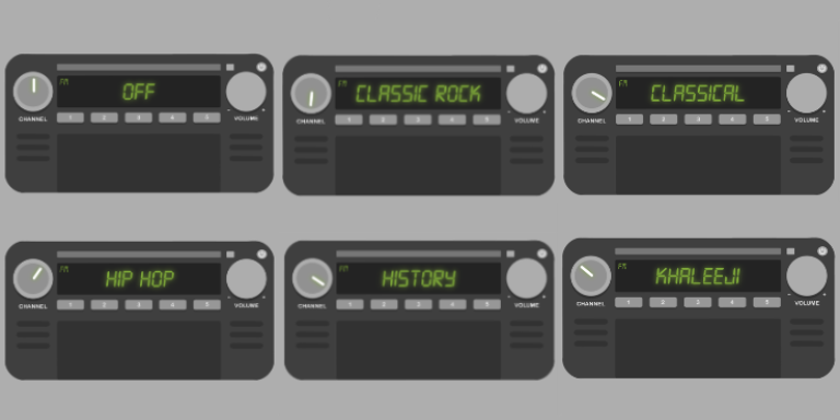
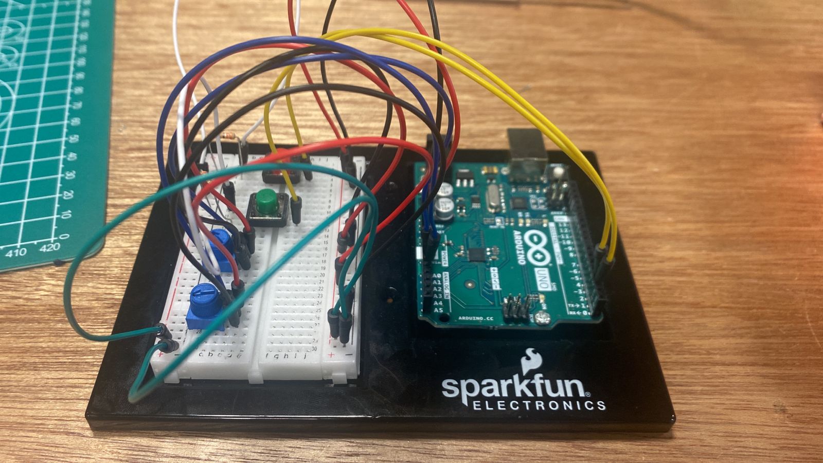
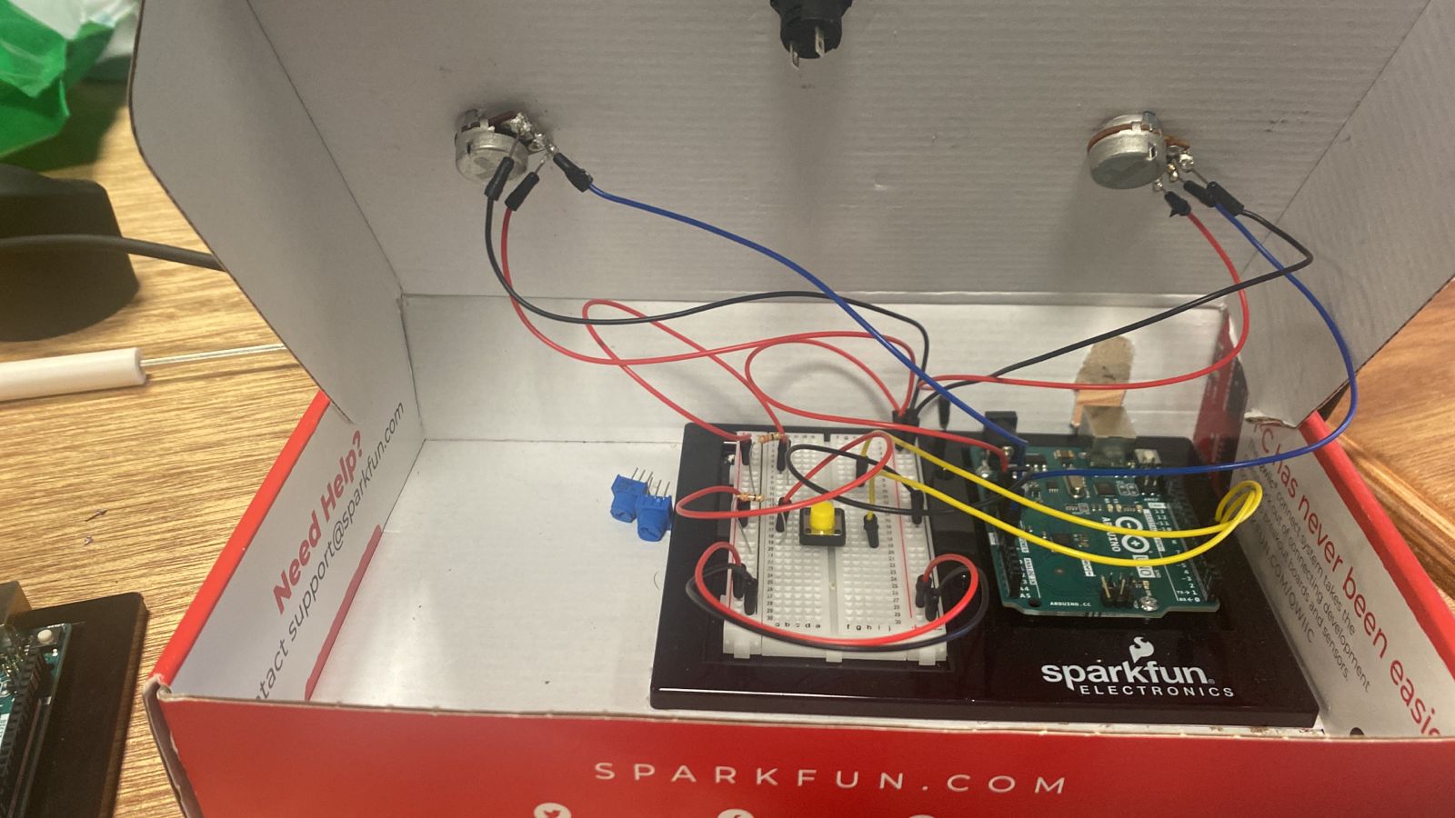
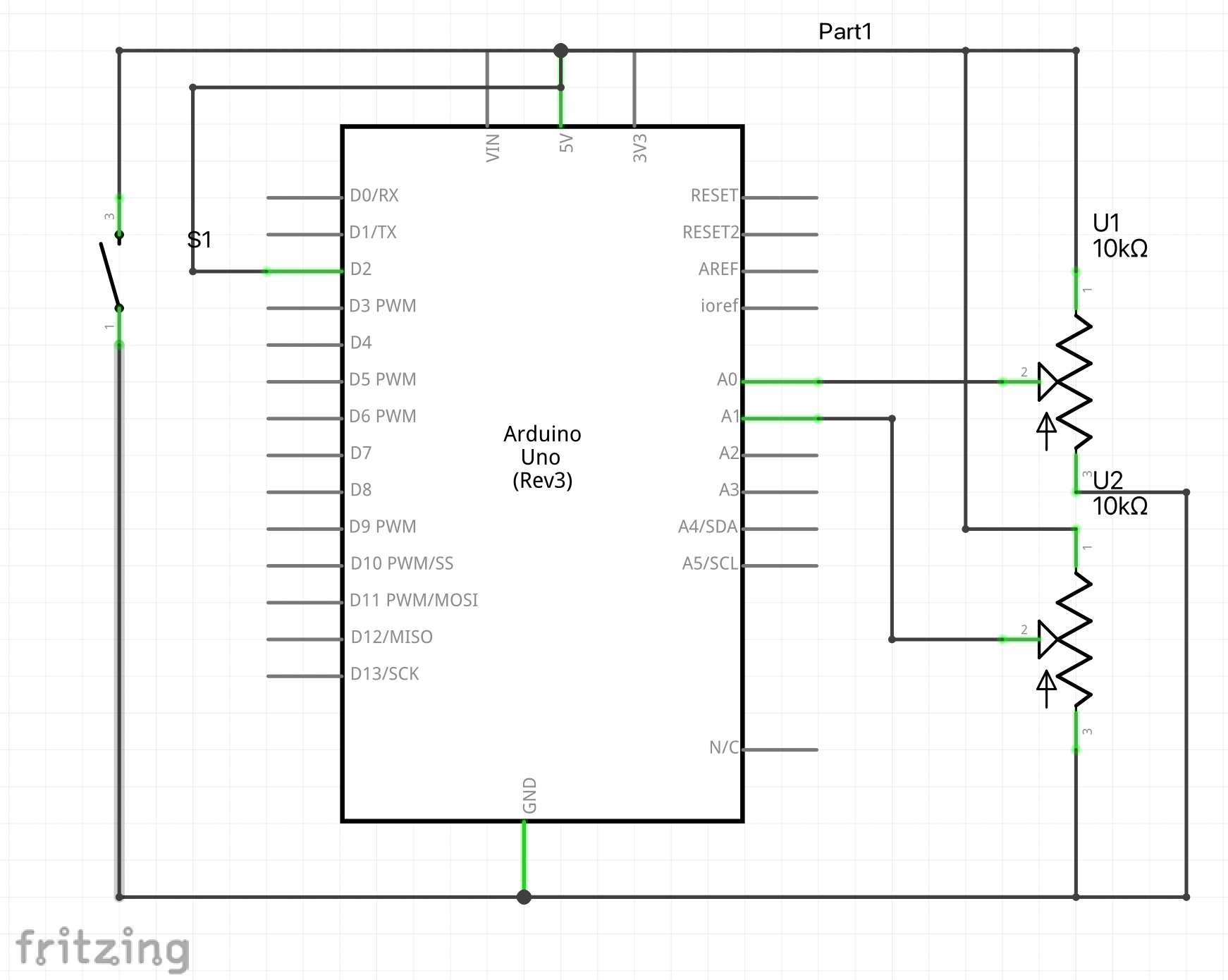
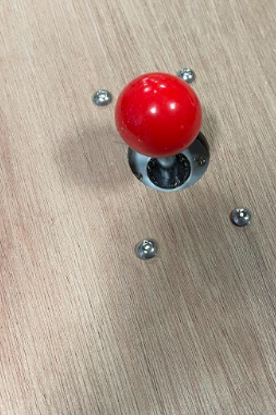
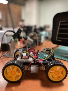
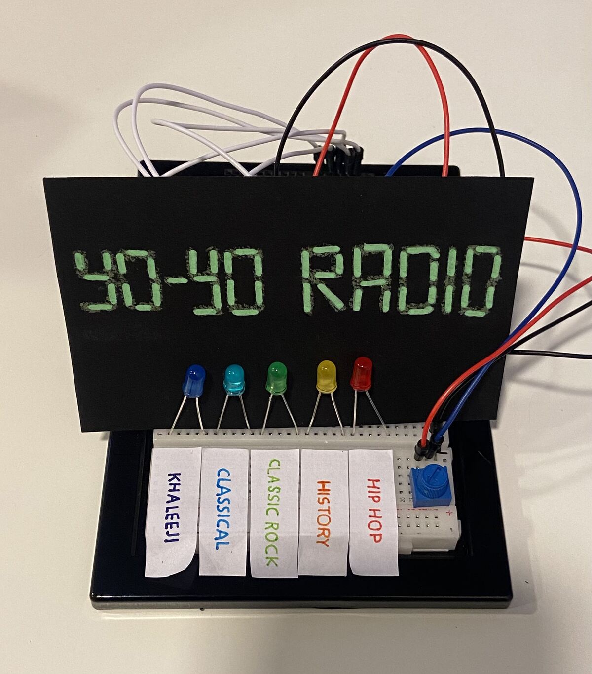
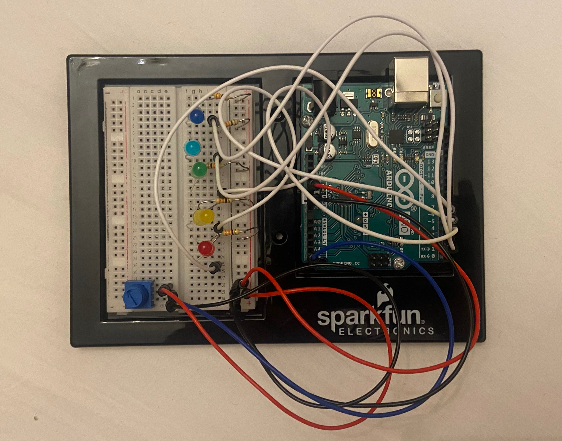
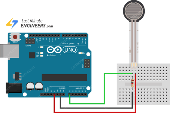
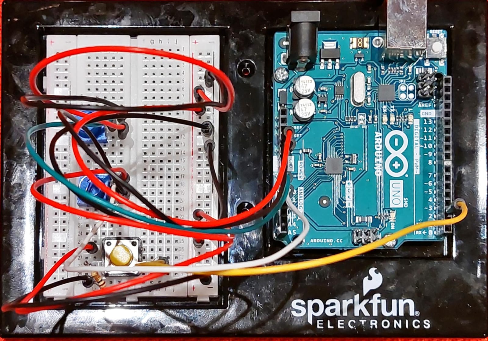
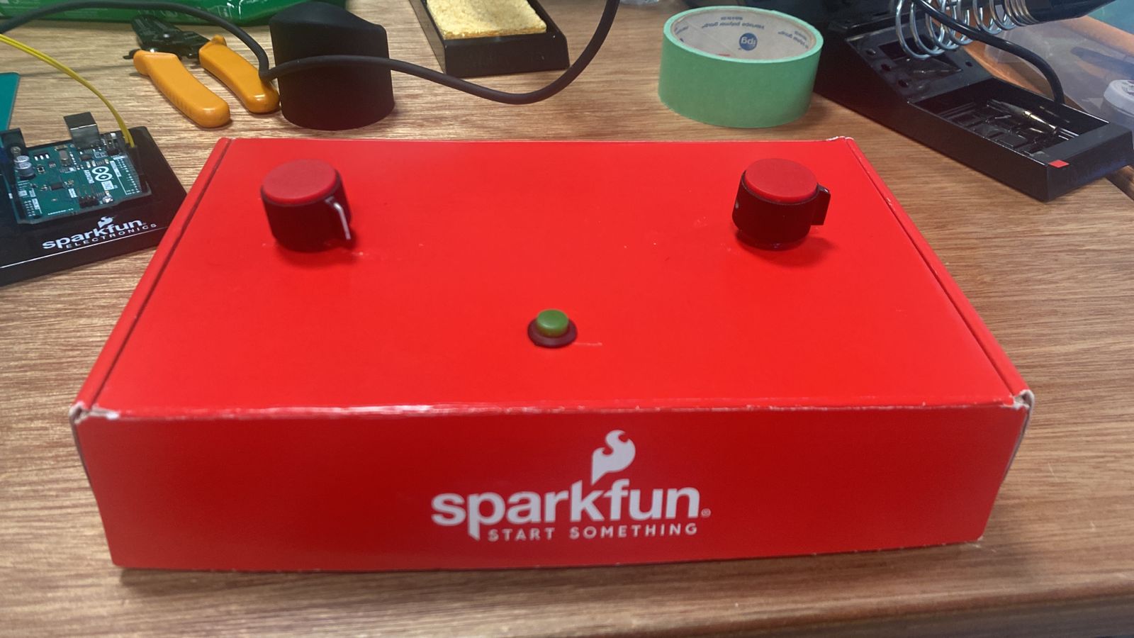
Arduino Board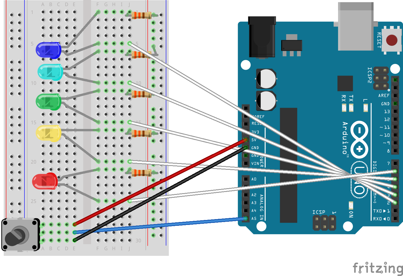
Video Demonstration
Click here to watch video demonstration
Highlights
- I’m proud of the fact that I was able to make an array for each channel without the program lagging.
- Figuring out the C++ coding for Arduino was challenging, but now I understand it enough to be able to modify it to include any last-minute changes.
- The p5 screen design (which I made on procreate).
- The glow function, which I was able to apply using this video tutorial:
Improvement
- Some other visual demonstration that indicates what channel you’re on. I would have liked for the background to possibly show the sound waves of the song playing and in the color of the designated channel.
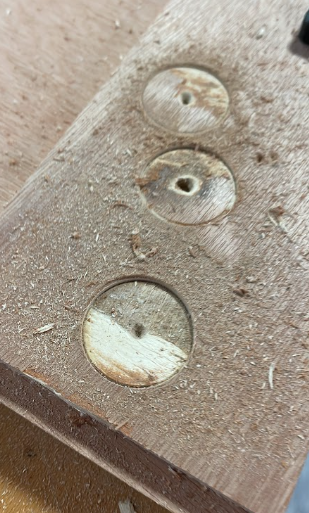
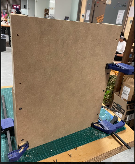
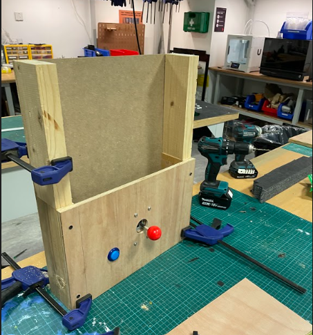
- I also wanted to do something more for the physical presentation of the Arduino board, though I was able to customize it just a little using some card paper.


_ztBMuBhMHo.jpg?auto=compress%2Cformat&w=140&h=140&fit=fill&bg=ffffff) Arduino UNO board
Arduino UNO board Breadboard
 Rotary Potentiometers (2)
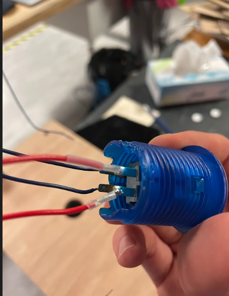
 Push down Switch (1)
 Resistors
 Jumper Wires
 Arduino IDE