Musical Instrument!

This week’s assignment was, by far, the most difficult one for me. Not because it required a lot of coding or wiring, but because pushing myself mentally to plan and execute something completely unfamiliar was tough! But I am proud that I did it, despite taking some time to make it work. So, let’s see what I got here.

💡 idea

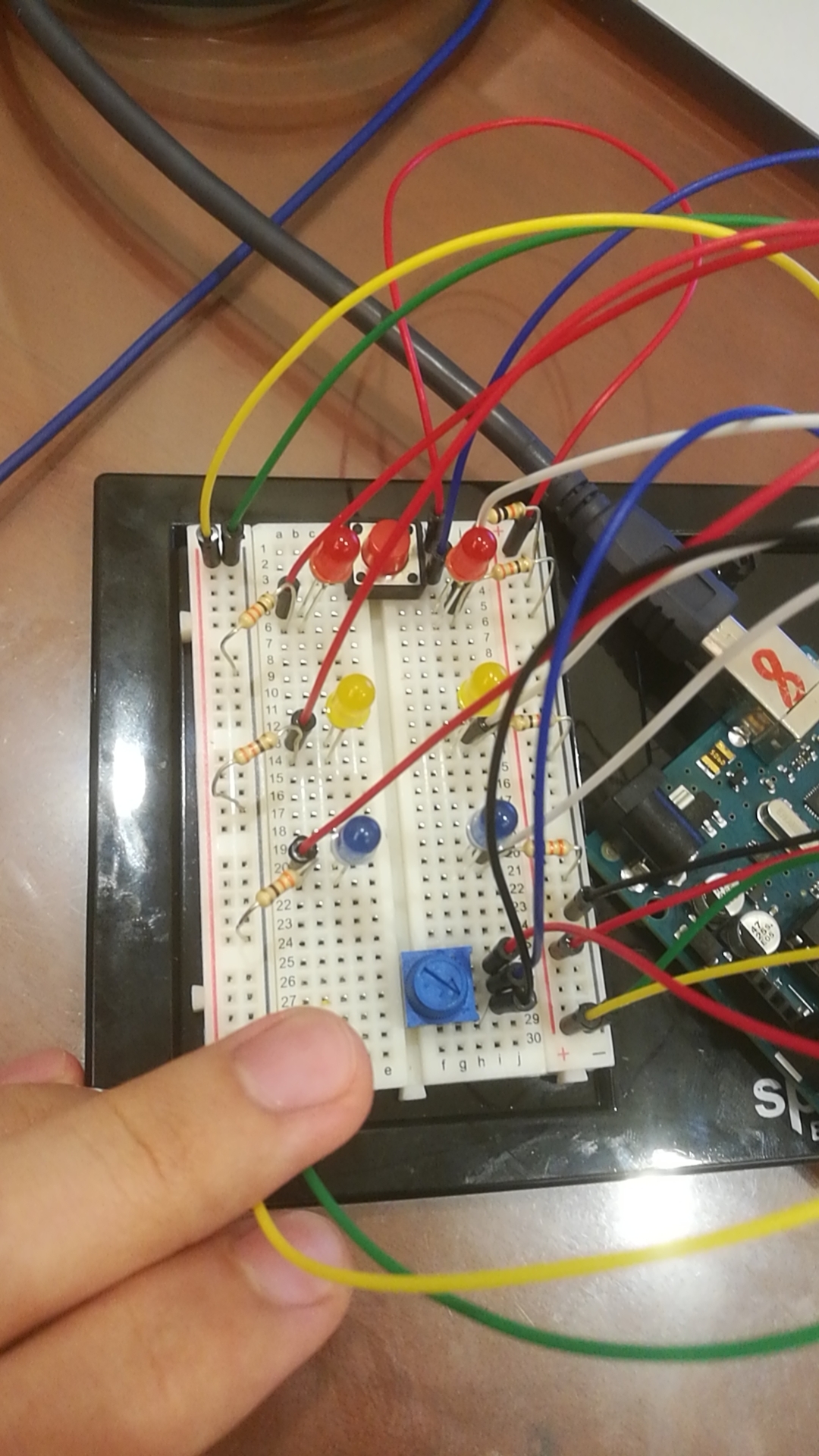
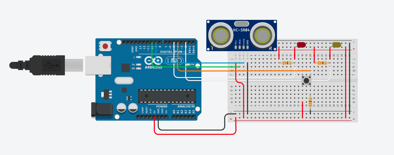
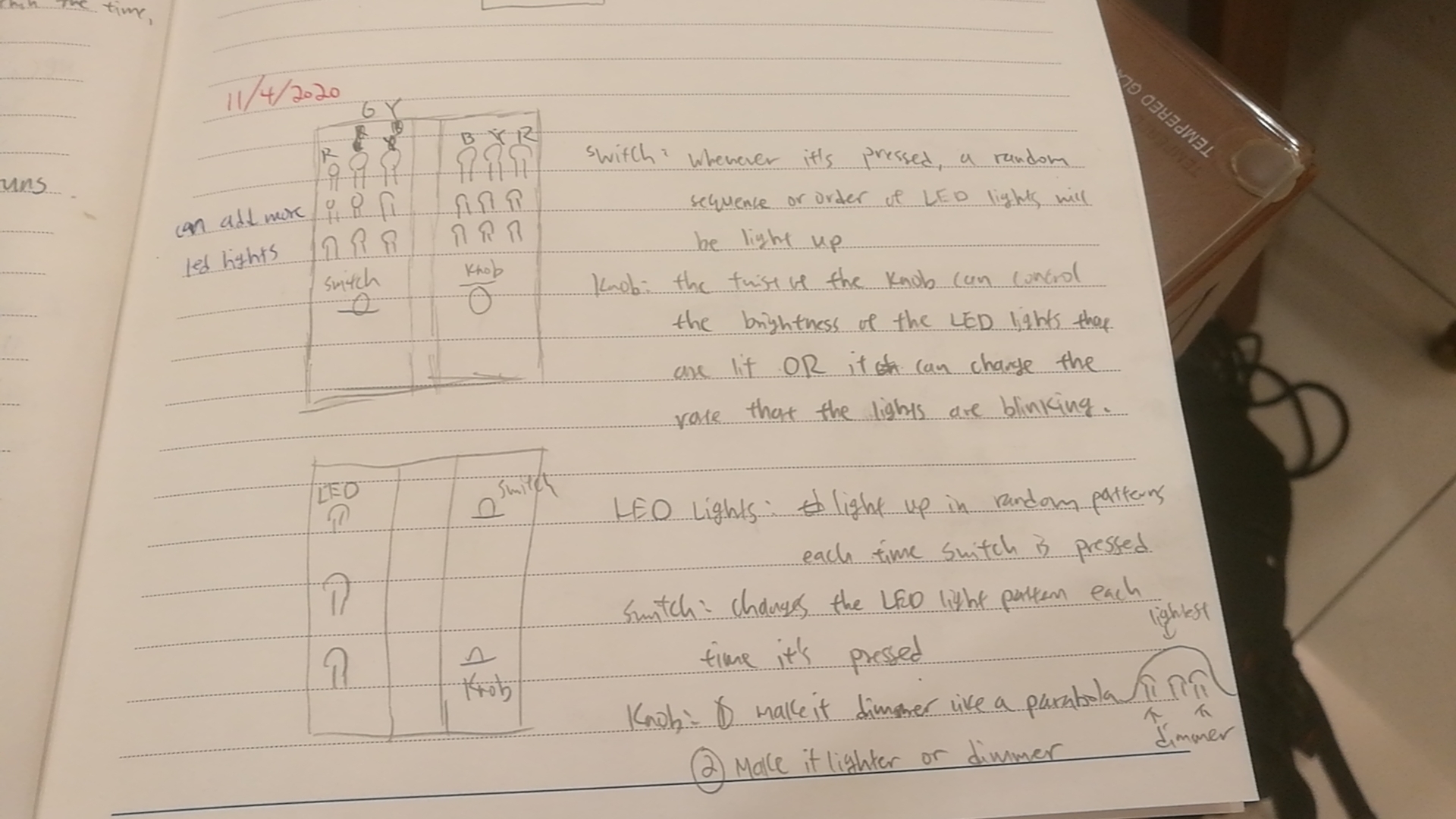
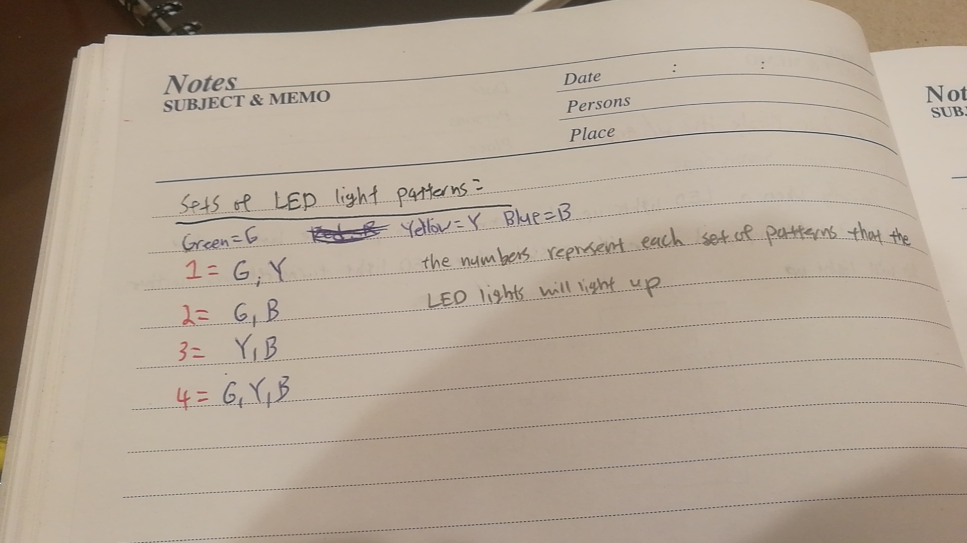
The idea was to use a switch, an LED light, and a potentiometer to produce some kind of sound altogether to create a musical instrument.

🛠 process

After getting all of the circuit elements, I started to experiment with sounds. I wired my button and wrote the code so that every time I press it, one particular sound plays. Then, I wired a potentiometer and connected it to the LED through the code so that the lighting changes with the potentiometer values. I later added the sounds so that they begin to play whenever the LED is on. The whole system can be turned off by pressing the switch.

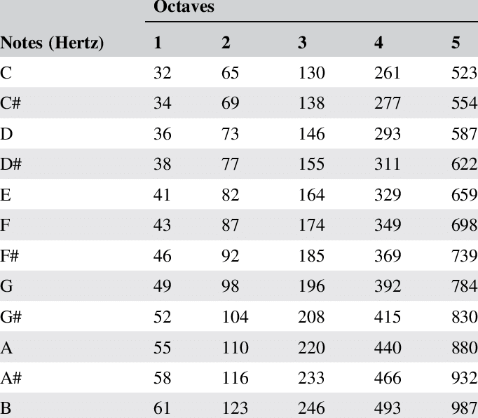
The primary challenge was to make sure that the tone() is producing clean notes and not just noise. I guess this depends more on the frequency and duration of the sound, but in the beginning, some of my sounds were like noise. I was able to overcome this by adding delay() and reducing the duration of each sound.

I was talking a bit about the mental challenge at the beginning of the post, and for me personally, it was believing in the idea that hardware and circuits can produce sound! I was struggling for about two days because I couldn’t come up with the idea, but then it finally hit me after some trial and error!

🎼 demo

#include "pitches.h"

int speakerPin = 4;
int ledPin = 2;
int button = 7;
// int photoPin = A0;
int potenPin = A2;
int prevState = 0;
boolean flag = false;
int notes[11] = {NOTE_C4, NOTE_D4, NOTE_E4, NOTE_DS2, NOTE_E2, NOTE_F2, NOTE_FS2, NOTE_G2, NOTE_GS2, NOTE_A2, NOTE_AS2};
int durations[11];
int whichNote = 0;

void setup() {
  // put your setup code here, to run once:
  pinMode(ledPin, OUTPUT);
  pinMode(button, INPUT);
  Serial.begin(9600);
}

void loop() {
  // read button state
  int buttonState = digitalRead(button);

  // if button is pressed, run the program
  if (buttonState == 1 && prevState == LOW){
    flag = !flag;
    tone(speakerPin, notes[0], 300);
    delay(500);
  }

  if (flag){
    int ledValue = analogRead(potenPin);
    
    analogWrite(ledPin, ledValue/4);
    Serial.println(digitalRead(ledPin == HIGH));
    
    if(digitalRead(ledPin)){
      for (int i = 0; i<10; i++){
        tone(speakerPin, notes[i+1], 300);
        delay(200);
      }
    }    
  }
  else {
      pinMode(ledPin, LOW);
    }

  // track button state
  prevState = buttonState;
}

/*************************************************

 * Public Constants

 *************************************************/

#define NOTE_B0  31
#define NOTE_C1  33
#define NOTE_CS1 35
#define NOTE_D1  37
#define NOTE_DS1 39
#define NOTE_E1  41
#define NOTE_F1  44
#define NOTE_FS1 46
#define NOTE_G1  49
#define NOTE_GS1 52
#define NOTE_A1  55
#define NOTE_AS1 58
#define NOTE_B1  62
#define NOTE_C2  65
#define NOTE_CS2 69
#define NOTE_D2  73
#define NOTE_DS2 78
#define NOTE_E2  82
#define NOTE_F2  87
#define NOTE_FS2 93
#define NOTE_G2  98
#define NOTE_GS2 104
#define NOTE_A2  110
#define NOTE_AS2 117
#define NOTE_B2  123
#define NOTE_C3  131
#define NOTE_CS3 139
#define NOTE_D3  147
#define NOTE_DS3 156
#define NOTE_E3  165
#define NOTE_F3  175
#define NOTE_FS3 185
#define NOTE_G3  196
#define NOTE_GS3 208
#define NOTE_A3  220
#define NOTE_AS3 233
#define NOTE_B3  247
#define NOTE_C4  262
#define NOTE_CS4 277
#define NOTE_D4  294
#define NOTE_DS4 311
#define NOTE_E4  330
#define NOTE_F4  349
#define NOTE_FS4 370
#define NOTE_G4  392
#define NOTE_GS4 415
#define NOTE_A4  440
#define NOTE_AS4 466
#define NOTE_B4  494
#define NOTE_C5  523
#define NOTE_CS5 554
#define NOTE_D5  587
#define NOTE_DS5 622
#define NOTE_E5  659
#define NOTE_F5  698
#define NOTE_FS5 740
#define NOTE_G5  784
#define NOTE_GS5 831
#define NOTE_A5  880
#define NOTE_AS5 932
#define NOTE_B5  988
#define NOTE_C6  1047
#define NOTE_CS6 1109
#define NOTE_D6  1175
#define NOTE_DS6 1245
#define NOTE_E6  1319
#define NOTE_F6  1397
#define NOTE_FS6 1480
#define NOTE_G6  1568
#define NOTE_GS6 1661
#define NOTE_A6  1760
#define NOTE_AS6 1865
#define NOTE_B6  1976
#define NOTE_C7  2093
#define NOTE_CS7 2217
#define NOTE_D7  2349
#define NOTE_DS7 2489
#define NOTE_E7  2637
#define NOTE_F7  2794
#define NOTE_FS7 2960
#define NOTE_G7  3136
#define NOTE_GS7 3322
#define NOTE_A7  3520
#define NOTE_AS7 3729
#define NOTE_B7  3951
#define NOTE_C8  4186
#define NOTE_CS8 4435
#define NOTE_D8  4699
#define NOTE_DS8 4978
🎲 next steps

For now, the musical instrument is fairly simple, and the next steps would probably be adding some interactivity – perhaps adding different sounds as the potentiometer values change or adding a non-switch button to add more sounds.
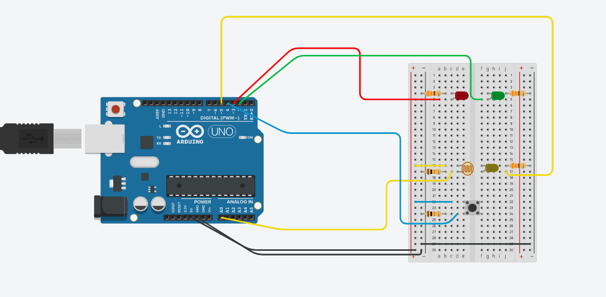
Analog Musical Instrument

const int blueButton = 6;
const int servoPin = 9;
const int songLength = 8;
const int tempo = 115;

const int noteC3 = 130;
const int noteD3 = 146;
const int noteE3 = 164;
const int noteF3 = 174;
const int noteG3 = 196;
const int noteA3 = 220;
const int noteB3 = 246;


const int noteC4 = 261;
const int noteD4 = 293;
const int noteE4 = 329;
const int noteF4 = 349;
const int noteG4 = 392;
const int noteA4 = 440;
const int noteB4 = 493;
const int noteC5 = 523;

const int noteD5 = 587;
const int noteE5 = 659;
const int noteF5 = 698;
const int noteG5 = 784;
const int noteA5 = 880;
const int noteB5 = 987;


//int musicNotes[] = {noteC4, noteD4, noteE4, noteF4, noteG4, noteA4, noteB4, noteC5};
int musicNotes[] = {noteC5, 0, noteE5, 0, noteG5, 0, noteB5, 0};
int musicNotes2[] = {noteC4, 0, noteE4, 0, noteG4, 0, noteB4, 0};
int musicNotes3[] = {noteC3, 0, noteE3, 0, noteG3, 0, noteB3, 0};
int noteDuration[] = {2, 4, 2, 4, 4, 2, 4, 2};

void setup() {
  pinMode(servoPin, OUTPUT);
  pinMode(blueButton, INPUT_PULLUP);
  Serial.begin(9600);
}
void loop() {
 lightSensor();
  button();


}

//new tab: button
void button() {

  
  bool bluebuttonState = digitalRead(blueButton);
  if (bluebuttonState == HIGH) {
    for (int i = 0; i < songLength; i++) {

      int duration =   noteDuration[i] * tempo;

      tone(servoPin, musicNotes2[i], duration);
      delay(duration); //make the length of the time = length of the musical note(frequency)
      delay(15);

    }
  }    else {
    for (int i = 0; i < songLength; i++) {

      int duration =   noteDuration[i] * tempo;

      tone(servoPin, musicNotes[i], duration);
      delay(duration); //make the length of the time = length of the musical note(frequency)
      delay(15);


    };


  };

};
//new tab light sensor
void lightSensor() {
  int analogValue = analogRead(A0);
 Serial.print(analogValue);
  if (analogValue < 10) {
   Serial.println(" - Dark");
//   //add music note here
  } else if (analogValue < 200) {
   Serial.println(" - Dim");
    for (int i = 0; i < songLength; i++) {

     int duration =   noteDuration[i] * tempo;

     tone(servoPin, musicNotes3[i], duration);
     delay(duration); //make the length of the time = length of the musical note(frequency)
     delay(15);

    }

  }  };


Documentation:

Idea: Create sound directly from Arduino, like a musical drone sound by changing the musical notes from C4 to C5 when you click on the button or change from either to a 3rd octave when you dim the light sensor (all by changing the frequency from within the motor).

Positives:

I like how I could manipulate the motor sound based on its frequency to create a tone and tempo.In addition to that I was able to play around with that frequency within the motor to create an array of musical notes with different octaves. Once I could adjust the tempo and time spacing between notes through looping the array, I was able to integrate that into different parts of the code.

I like that I was able to introduce different noises from the motor by adding in different components that trigger different sounds like the button and sensor.

This was also surprisingly fun compared to other assignments for me because I learned that Arduino could be used for more than just LED circuits etc but you can incorporate and manipulate other media like sound.

Negatives:

I don’t think its particularly musical, however I think it follows the rules of music in terms of octaves and musical notes.


Nathan analog + digital Assignment

For this week’s assignment, I wanted to do a ghostbuster (kind of, not really) themed project. The idea is to use the potentiometer to find the position of the ghost, while the lights fade.

General instructions

The player is entering a house that is infested with ghosts. First, they have to click the red button on the right to activate the ghost-catching device. The ghost-catching device has five red LEDs, marking the general 5 directions in front of the player. When the lights in the house are on, all five device lights are on, as the surrounding is too bright to detect anything.

As the lights in the ghost-infested house are dimmed, the ghosts begin to reveal themselves. They are quick and barely leave marks, so the lights on the device are usually all lighting chaotically. The player then turns the knob to try and pinpoint the ghost locations.

The ghost changes its location every second. If the direction the knob is pointing to aligns with the ghost’s location, the correlating light on the device will shine, revealing that location to the player.

Troubles

I ran into a lot of problems for this week’s assignment. Some kind of dumb, for example, I forgot the ground the red button and was very confused about the chaotic lights that were flashing for quite some time.

I think the most useful challenge that I faced was trying to organize functions, specifically the logic of the functions and their conditions. There are many steps and phases in my project this week. When I began to code the project, I didn’t really use functions, and the loop function was a mess. So I redesigned my code and tried to compartmentalize each step. This helped a lot, but the order that the functions ran was also something that needed to be taken care of.

Wiring

For the wiring of this project, I had one digital button that inputs ON/OFF to the Arduino wired on the right side of the breadboard. There are five red LEDs to signify the device location lights, a potentiometer that signifies the controls for the ghost device, and a photoresistor that signifies the lights in the haunted hosue

Code

int button = 2;
int led1 = 4;
int led2 = 6;
int led3 = 8;
int led4 = 10;
int led5 = 12;
bool led1state = false;
bool led2state = false;
bool led3state = false;
bool led4state = false;
bool led5state = false;
bool prevB = false;
//timer for fake ghost position
long timer;
int timerlength = 50;
//timer for real ghost position
long timer1;
int timerlength1 = 1000;
int ghostPosition;
int truePosition;


void setup() {
  pinMode(button, INPUT);
  pinMode(led1, OUTPUT);
  pinMode(led2, OUTPUT);
  pinMode(led3, OUTPUT);
  pinMode(led4, OUTPUT);
  pinMode(led5, OUTPUT);
  
  Serial.begin(9600);
  timer = millis() + timerlength;
  timer1 = millis() + timerlength1;
}

void loop() {
  deviceon();
  //shifting the ghost's true position every second
  if (millis() > timer1){
    truePosition = random(1,6);
    timer1 = millis() + timerlength1;
  }
}

//function for turning the ghost catching device on
void deviceon() {
  int buttonstate = digitalRead(button);
  if (buttonstate == HIGH && prevB == LOW){
    deviceSwitch();
  }
  digitalWrite(led1, led1state);
  digitalWrite(led2, led2state);
  digitalWrite(led3, led3state);
  digitalWrite(led4, led4state);
  digitalWrite(led5, led5state);
  prevB = buttonstate;
  lightsoff();
}

//turning the ghost device lights on or off
void deviceSwitch() {
  led1state = !led1state;
  led2state = !led2state;
  led3state = !led3state;
  led4state = !led4state;
  led5state = !led5state;
}

//fake ghost position lights
void ghost() {
  if (millis() > timer){
    ghostPosition = random(1,6);
    
    if (ghostPosition == 1){
      digitalWrite(led1, true);
    }
    else if (ghostPosition != 1){
      digitalWrite(led1, false);
    }
    
    if (ghostPosition == 2){
      digitalWrite(led2, true);
    }
    else if (ghostPosition != 2){
      digitalWrite(led2, false);
    }
    
    if (ghostPosition == 3){
      digitalWrite(led3, true);
    }
    else if (ghostPosition != 3){
      digitalWrite(led3, false);
    }

    if (ghostPosition == 4){
      digitalWrite(led4, true);
    }
    else if (ghostPosition != 4){
      digitalWrite(led4, false);
    }
    
    if (ghostPosition == 5){
      digitalWrite(led5, true);
    }
    else if (ghostPosition != 5){
      digitalWrite(led5, false);
    }
    
    timer = millis() + timerlength;
  }
}

//what happens when the house lights are off
void lightsoff() {
  int light = analogRead(A0);
  if (light <= 250){

    led1state = false;
    led2state = false;
    led3state = false;
    led4state = false;
    led5state = false;
    ghost();
    catching();
  }
}

//function for the potentiometer, catching the true position
void catching() {
  int knobValue = analogRead(A1);
  Serial.println(knobValue);
  int knobPosition;

  if (270 < knobValue && knobValue <= 360){
    if (truePosition == 5){
      led5state = !led5state;
      led1state = false;
      led2state = false;
      led3state = false;
      led4state = false;
    }
  }
  if (360 < knobValue && knobValue <= 480){
    if (truePosition == 4){
      led4state = !led4state;
      led1state = false;
      led2state = false;
      led3state = false;
      led5state = false;
    }
  }
  if (480 < knobValue && knobValue <= 650){
    if (truePosition == 3){
      led3state = !led3state;
      led1state = false;
      led2state = false;
      led4state = false;
      led5state = false;
    }
  }
  if (650 < knobValue && knobValue <= 730){
    if (truePosition == 2){
      led2state = !led2state;
      led3state = false;
      led1state = false;
      led4state = false;
      led5state = false;
    }
  }
  if (730 < knobValue && knobValue <= 800){
    if (truePosition == 1){
      led1state = !led1state;
      led2state = false;
      led3state = false;
      led4state = false;
      led5state = false;
    }
  }

}

Demonstration

The Police

In this weeks assignment I was inspired by current protests in Poland. The police lights are flashing all the time in Warsaw nowadays and I wanted to have some control over that. At least on my mini Arduino board 🙂

I decided to have two modes, which I could switch around by pressing the button. One is the rapid mode, where the two LEDs blink rapidly in the police fashion. The other is the controlled mode, where the user can switch between the two LEDs by the means of the potentiometer. By doing that, they can control the LEDs and almost play with them just as the DJs do with their sounds decks .

And here is my code:

int buttonPin = 2;
int blueLedPin = 7;
int redLedPin = 8;
int prevBtnState = 0;
bool mode1 = true;
long timer = 0;
long debounce = 200;

void setup() {
  pinMode(blueLedPin, OUTPUT);
  pinMode(redLedPin, OUTPUT);
  pinMode(buttonPin, INPUT);
  Serial.begin(9600);
}

void loop() { 
  int knobValue = map(analogRead(A0), 190, 860,  10, 500);
  int btnState = digitalRead(buttonPin);
  
  if (!btnState && prevBtnState  && millis() - timer > debounce){
    mode1 = !mode1;
    timer = millis();
  }  
  
  if (mode1) {
    Serial.println("MODE 1");
      digitalWrite(redLedPin, HIGH);
      delay(75);
      digitalWrite(blueLedPin, HIGH);
      delay(75);
      digitalWrite(redLedPin, LOW);
      delay(75);
      digitalWrite(blueLedPin, LOW);
      delay(75);
  }
  else {
      if (knobValue < 250) {
        digitalWrite(blueLedPin, HIGH);
        digitalWrite(redLedPin, LOW);
      }
      else {
        digitalWrite(blueLedPin, LOW);
        digitalWrite(redLedPin, HIGH);
      }
  }  
  prevBtnState = btnState;
}

Week 8: Emotion-O-Meter

Intro

Brainstorming for this week was pretty tough. I went from playing around with the potentiometer and ultrasonic sensor to choosing to prioritize adding signifiers and things that add more context to a project. I personally think I could’ve done something more complex or experimented more with sensors, but by the time I reached this realization I was in too deep in this assignment. However, I will make it a goal to explore the sensors and switches I still haven’t touched in the kit (temperature sensor, photoresistor, and switch).

Note: check this link for a good starting point on Ultrasonic Sensors:

Idea 

After brainstorming and trying to find inspiration, I decided to make use of the potentiometer’s movement in a circular motion and wanted to do something that has to do with the user needing to point the arrow of the potentiometer towards a specific thing to get a specific interaction.

So, the potentiometer was my source of analog input.

For this, I recalled the feeling charts I used to have in kindergarten, as well as the reversible octopus plushie that took over TikTok. Both these things are tools meant to make it easier for children to express their emotions without having to struggle through verbalizing it.

Feelings Chart Example 
Octopus Plushie


So, I thought it would be interesting to do something similar. The user inputs their feeling by twisting the dial to a certain quadrant in a circle cutout that I added to my circuit. An LED to the emotion lights up. Then, for the digital input and output, I used a simple button and LED, and the user turns on the LED if they feel like they want to talk further about why they feel the way they feel.

Add-ons to Circuit


Implementation

In terms of the code, it was actually pretty simple. I just read through the values that the knob gives on the serial monitor, and added ranges for each LED to turn on accordingly. So, for the yellow quadrant of the circle the range was 220 – 186, and so if the user turns it and the reading is in that range, the yellow LED turns on and the rest turn off. As for the digital part, I just applied the switch example we looked over in class.

Here’s a demo:

(Okay, I did actually film horizontally, I’m not exactly sure why the video still turned out like this 🙁 (help))

Reflection and Development

I really enjoy the aspect of adding a story or context to what I’m making, it somehow makes the process much easier and I enjoyed doing that here. However, I do think I could’ve gone for something a bit more complex to push myself and really get comfortable with working with analog inputs. I think one of the main issues I have in this program is that the varying of brightness in the LED lights doesn’t make much sense in context, and I want to look into how to use elements of analog output for my benefit and to enrich my ideas. Any suggestions or insight is appreciated as always :-)!

Code 

//define variables for button and LEDs
int button = 2;
int yellowLed = 11;
int greenLed = 10;
int blueLed = 9;
int redLed = 6;
int expressionLed = 3;

//booleans to check if the button is pressed + to turn LED on (digital)
bool prevButtonState = LOW;
bool expressionLedState = false;

//determining knob input for the dial
int knob = A0;

void setup() {
  pinMode(yellowLed, OUTPUT);
  pinMode(greenLed, OUTPUT);
  pinMode(blueLed, OUTPUT);
  pinMode(redLed, OUTPUT);
  pinMode(button, INPUT);
  pinMode(expressionLed, OUTPUT);
  Serial.begin(9600);
  // put your setup code here, to run once:

}

void loop() {
  // put your main code here, to run repeatedly:
  int knobValue = analogRead(knob);
  int mappedValue = map(knobValue, 0, 1023, 0, 220); //i thought mapping to 220 rather than 255 could be helpful, since my circle has 4 divisions, but it didn't make much of a difference. 
   

  if (mappedValue >= 186) { //first quadrant, very happy
    analogWrite(greenLed, 0);
    analogWrite(blueLed, 0);
    analogWrite(redLed, 0);
    analogWrite(yellowLed, mappedValue);

  }
  else if (mappedValue <= 185 && mappedValue >= 105) { //second quadrant, happy
    analogWrite(yellowLed, 0);
    analogWrite(blueLed, 0);
    analogWrite(redLed, 0);
    analogWrite(greenLed, mappedValue);

  }
  else if (mappedValue <= 104 && mappedValue >= 22) { //third quadrant, neutral
    analogWrite(greenLed, 0);
    analogWrite(yellowLed, 0);
    analogWrite(redLed, 0);
    analogWrite(blueLed, mappedValue);

  }
  else if (mappedValue <= 21 && mappedValue >= 0) { //fourth quadrant, sad
    analogWrite(greenLed, 0);
    analogWrite(yellowLed, 0);
    analogWrite(blueLed, 0);
    analogWrite(redLed, mappedValue);
    if (mappedValue <= 5){
      analogWrite(redLed, mappedValue + 5); //to avoid light turning off
    }

  }
  //digital, turns on an LED if the individual presses it
  int buttonState = digitalRead(button);
  if(buttonState == HIGH && prevButtonState == LOW){
  expressionLedState = !expressionLedState;
  }
  digitalWrite(expressionLed, expressionLedState); 
  prevButtonState = buttonState;


  //analogWrite(led,mappedValue);
//  Serial.print(knobValue);
//  Serial.print(" ");
//  Serial.println(mappedValue);

}


Alarm System – Analog and Digital Sensors

I would like to start off by saying that I’m actually not very proud of my assignment this week. This is because, for the first time, I felt like I didn’t really go beyond what we did in class.
However, the reason for this is that I found out that I have not yet grasped what we did last week. Therefore, I took the time to watch the recorded lectures and read some online resources to fully understand the basics of input and output. This took up most of the time I had for this week’s assignment, so I decided to keep it simple and just use what I have learned to make sure that I now knew how to handle analog and digital input/output.

idea

Trying to incorporate everything that I have learned so far, I came up with this idea. I wanted to create some sort of alarm system, but with a visual signal (represented by a flashing LED) instead of sound.

In the circuit, there are 3 LEDs, 1 push button, and 1 photoresistor.
2 LEDs (green and red) are digital output, and the other LED (yellow) is an analog output.
Initially, the red and yellow LEDs are off. The green LED is on, meaning the alarm system hasn’t been triggered.
The closer you get to the photoresistor, the brighter the yellow LED lights up, signaling that something is getting close.
When you actually touch the photoresistor, the alarm system is triggered: the green LED turns off, the yellow LED is at its brightest, and the red LED starts to flash.
If you want to turn off the “alarm”, you press the button which turns the green LED back on and the red LED off.

NOTe

I also ended up adding a boolean alarmStopped that does the following:

        • If something touches the photoresistor but doesn’t move away and stays still, you can still shut off the alarm.
        • As soon as it moves and touches the photoresistor again, the alarm system is triggered once again.

circuit and code

int green = 2; //green LED
int red = 3; //red LED
bool redState = LOW;
int b = 4; //buton
bool prevBState = LOW; //to check previous button state
int yellow = 5; //yellow LED
int pr = A0; //photoresitor
bool alarm; //to check if alarm is triggered
bool alarmStopped; //to check if alarm has been stopped
//timer to make yellow LED flash
long timer;
int timerLength = 100;

void setup() {
  // put your setup code here, to run once:
  Serial.begin(9600);
  pinMode(red,OUTPUT);
  pinMode(green,OUTPUT);
  pinMode(yellow,OUTPUT);
  pinMode(b,INPUT);
  pinMode(pr,INPUT);
  alarm = false;
  alarmStopped = false;
  digitalWrite(red,LOW);
  digitalWrite(green,HIGH);
  timer = millis();
}

void loop() {
  // put your main code here, to run repeatedly:
  //analog read photoresistor values
  int prValue = analogRead(pr); 
  //digitally read current button state
  int bState = digitalRead(b); 
  
  //Serial.println(prValue);
  
  //map the photoresistor value (from min 270 to max 640) to the LED needed value 
  //and constrain it between those values 0 and 255
  int mappedValue = 255- constrain(map(prValue,270,640,0,255),0,255);
  //light the yellow LED according to the photoresistor value
  analogWrite(yellow,mappedValue);
  
  //Serial.println(mappedValue);
  
  //in my case, the photoresistor has been touched when the LED value is around 150
  if (mappedValue > 150 && alarmStopped == false)
  {
    alarm = true;
  }
  //if alarm has been triggered, flash red LED and turn off green LED
  if (alarm == true)
  {
    if (millis()>timer){
      redState = !redState;
      timer = millis() + timerLength;
    }
    digitalWrite(red,redState);
    digitalWrite(green,LOW);
  }
  //if button has been pressed
  if (bState == HIGH && prevBState == LOW)
  {
    alarmStopped = true; //alarm system has been stopped
    alarm = false; //alarm is not currently triggered
    digitalWrite(red,LOW); //turn off red LED
    digitalWrite(green,HIGH); //turn green LED back on
  }
  prevBState = bState; //update the previous button state every frame
  //this is to allow the button to turn off the alarm
  //even if we're still touch the photoresistor
  //however the alarm will be triggered again if you move and touch the photoresistor once more 
  if (alarm == false && mappedValue< 150)
  {
    alarmStopped = false;
  }
}


Final outcome

Day/Night Arduino Simulation

For probably the first time since we started the semester, I was able to do a weekly assignment just as I planned it initially. As soon as we were assigned to include some analog sensor in our circuit and a digital one, I thought of the photocell (because it’s just so cool) and some application of it where the environment is dark and then is bright. I thought of having three bulbs, red, yellow, and green and as you get closer with your finger it changes from red to yellow to green. Then I thought of drawing a rabbit and a turtle and having bulbs as their eyes; if you get too close then the rabbit’s eyes brighten up, but if you are too far (bright environment)  the turtle’s eyes brighten up. But after a long time brainstorming, I decided to go with the most intuitive idea relating to darkness and light: day and night in real life.

Artistic (not so much) steps:

As visible, I draw small icons of the sun and the moon in order to represent day and night, where the yellow bulb would sit in the middle of the sun, and the white bulb will sit in the middle of the white crescent.

Process:

Learning from last assignment, I extrapolated the power and the ground to the rest of the board using two jumper wires, in order to give myself extra space to work with.

I put a button the middle as some kind of digital switch for the whole simulation, if you click once, it’s on and stays on until you click once again.

I put both bulbs in pins with the “~” sign next to them so that their pulse can be changed using the photocell readings.

I decided to make the simulation so that the yellow bulb is very bright (bright sun at the beginning of the day), and as you get your finger closer (as time passes throughout the day and light lessens) the brightness decreases until at one point it stops completely (the evening), and as you continue to get closer, the white bulb of the moon becomes brighter and bright (through the night), until it’s maximized when you physically touch the photocell and block almost all light (midnight), then as you move your finger back upwards the opposite happens (after midnight until dusk). The key is that I map the first values until half of the maximum reading of photocell into inverted values for the bulb so I would get that effect of a spectrum.

Struggles:

The only problem I faced was with the if conditions and digital/analog writing bearing in mind that I always do analogRead(); if I only had analogwrite() then the bulb would keep being bright, and of it’s only digitalWrite() then the bulb doesn’t turn on at all. I’m sure I had some errors in there which I was not able to deal with. So I decided to have two scenarios, if the simulation is on, read photocell and analogWrite() based on that, and if simulation is off then digitalWrite() the bulbs to be off.

Also, when I forgot to make “prevButtonState = buttonState” at the very end and rather had it inside the if statement, everything would work incorrectly, so that was another thing I learned.

The last issue was just that I had a non-working jumper wire, and a bulb that was probably not 100% functional, which caused some confusion for me at first but soon I realized the issue and resolved it.

Final Project Angle 1:

Final Project Angle 2:

The code for the assignment:

int button = 2;                 //button pin

int ledWhite = 3;               //white bulb pin
int ledState1;                  
int ledYellow = 5;              //yellow bulb pin
int ledState2
bool prevButtonState = LOW;     //initializing button to be unpressed

int knob = A0;                  //pin of photocell

void setup() {
 
  pinMode(button, INPUT);         //button initialized as input
  pinMode(ledWhite, OUTPUT);      //bulbs initialized as outputs
  pinMode(ledYellow, OUTPUT);
  
  Serial.begin(9600);
}

void loop() {
  int buttonState = digitalRead(button);              //storing reading from button
  Serial.println(buttonState);

  if (buttonState == HIGH && prevButtonState == LOW) {      //if button is clicked change the led states to their opposites
    ledState1 = !ledState1;
    ledState2 = !ledState2;
    }

  if (ledState1 == HIGH && ledState2 == HIGH) {           //if the bulbs were previously off then were turned on by button
      int knobValue = analogRead(knob);                   //store reading from photocell
      int mappedValue1 = constrain( map(knobValue, 596, 850, 0, 255), 0, 255);        //map the values from half the max until the max of the photocell readings into 0 -> 255 so that as they increase teh brightness increases, and constrain that within 0 to 255
      int mappedValue2 = constrain( map(knobValue, 340, 595, 255, 0), 0, 255);        //map the first values until half the max of photocell readings into 255 -> 0 so that as they increase the brightness decreases, and constrain that within 0 to 255
      
      
      Serial.println(knobValue);

    analogWrite(ledYellow, mappedValue1);             //change output of sun bulb accordingly
    analogWrite(ledWhite, mappedValue2);              //change output of moon bulb accordingly
    }
    
  else {
    digitalWrite(ledWhite, ledState2);              //make bulbs's state = LOW, hence turned off
    digitalWrite(ledYellow, ledState1);             //make bulb's state = LOW, hence turned off
    }

  prevButtonState = buttonState;                    //update prevButtonState in each loop
}


Week 8 Assignment: Analog Input and output, Mapping, data types, printing

INITIAL IDEA #1

For this week’s assignment, I originally thought of an idea where I would have different rows of LED lights on the breadboard along with a switch and a knob on a different row.

Whenever the switch is pressed, it will generate a random set of pattern or sequence that will light up different LED lights that will also be blinking on the breadboard. On the other hand, the knob will be able to control the blinking speed of those LED lights that are lit up.

IDEA #1.1

However, after thinking about the level of difficulty to make a total of 9 LED lights to light up in different patterns, I decided to decrease the amount of lights to just three. Also, I had changed my idea to not make the lights blink and to make 3 other LED lights to be controlled by the knob separately from the switch.

Initial Ideas for Setup
The LED Light patternsFinal Setup

Main Difficulties 

One of the major difficulties regarding the programming process for switching of LED light patterns was whenever I clicked the button, it does not switch to any of the other designated LED pattern. But, after a bit of debugging, I realized that I have to manually turn off all the LED lights everytime  the button starts to press and randomly generate a LED light pattern again.

One of the major difficulties regarding the programming behind making the LED lights dim or become brighter based on the knob is figuring out the entire logic behind it. I had to consult from Aaron regarding this problem and we had to search for an entire bell curve equation first, and figure out how to convert that into Arduino.

FINAL PRODUCT 


Interesting Thing…

I just found out that if I comment out one of my functions, the knobturn function, and leave the LEDfade 1,2,and 3 in the loop, it creates another amazing effect as originally in the knobturn function, I assigned every LED light with the brightness integer. However, I assigned it separately for each LED light (LEDfade1, LEDfade2, LEDfade3), therefore creating a fade effect.

MY CODE 

const int button = 2;

//digital LED lights
const int RedLed = 4;
const int YellowLed = 7;
const int BlueLed = 8;

//analog LED lights
const int RedLed1 = 3;
const int YellowLed1 = 5;
const int BlueLed1 = 6;

int RedLedState = LOW;
int YellowLedState = LOW;
int BlueLedState = LOW;

const int knob = A0;

int prevButtonState = LOW;
int randomNum;

//change spread to make bell curve wider or narrower
int spread = 60;

// set the postion to start above the screen so the first circle is dark
int bellCurveCenter = -spread;
//rewrite the array form in arduino
int ledPos [] = {
  160, 320, 480
};
int ledPosCount = 3; // the number of pins (i.e. the length of the array)
int ledIndex [] = {3, 5, 6};

void setup() {
  // put your setup code here, to run once:
  pinMode(button, INPUT);
  pinMode(knob, INPUT);

  pinMode(RedLed, OUTPUT);
  pinMode(YellowLed, OUTPUT);
  pinMode(BlueLed, OUTPUT);

  ////  ledPos = new int[3];
  //  // three different heights to put three different circle on screen
  //  ledPins[0] = 640/4;
  //  ledPins[1] = 640/2;
  //  ledPins[2] = 640 - 640/4;

  Serial.begin(9600);
}
//light up all three lights altogether first
//Each time the button's pressed, choose a random number (1-4)
//Light up the pattern that the chosen number corresponds to:
// If the number is 1, light up Green and Yellow
// If the number is 2, light up Green and Blue
// If the number is 3, light up Blue and Yellow
// If the number is 4, light up Green and Yellow and Blue
void loop() {
  buttonpress();
  LEDpattern();
  knobturn();
  LEDfade1();
  LEDfade2();
  LEDfade3();
}


void buttonpress() {

  int currentbuttonstate = digitalRead(button); //read current state of button
  if (currentbuttonstate == HIGH && prevButtonState == LOW) {
    randomNum = random(1, 5); //pick random number between 1 to 4
    Serial.println(randomNum);
  }
  prevButtonState = currentbuttonstate;
}

void LEDpattern() {
  //turn all LED lights offf irst
  digitalWrite(RedLed, LOW);
  digitalWrite(YellowLed, LOW);
  digitalWrite(BlueLed, LOW);

  if (randomNum == 1) {
    digitalWrite(RedLed, HIGH);
    digitalWrite(YellowLed, HIGH);
  }
  if (randomNum == 2) {
    digitalWrite(RedLed, HIGH);
    digitalWrite(BlueLed, HIGH);
  }
  if (randomNum == 3) {
    digitalWrite(YellowLed, HIGH);
    digitalWrite(BlueLed, HIGH);
  }
  if (randomNum == 4) {
    digitalWrite(RedLed, HIGH);
    digitalWrite(YellowLed, HIGH);
    digitalWrite(BlueLed, HIGH);
  }
}

void knobturn() {
  for (int thisPin = 3; thisPin < 7; thisPin++) {
    //taking the position of the circle and finding the distance of each LED from the center of our bell curve
    float distance = abs(ledPos[thisPin] - bellCurveCenter);
    // this is the formula for the bell curve, multiply by 255 to put in the proper range for brightness
    float brightness = exp(-0.5 * pow(distance / spread, 2.)) * 255;
    analogWrite(ledIndex[0], brightness);
    analogWrite(ledIndex[1], brightness);
    analogWrite(ledIndex[2], brightness);
  }
}

void LEDfade1() {
  int knobvalue = analogRead(knob);
  Serial.print(knobvalue);

  //might need to add an int before map, but test it out first
  bellCurveCenter = map(knobvalue, 0, 1023, -200, 640 + spread);

  //  for (int thisPin = 3; thisPin < 7; thisPin++) {
  //taking the position of the circle and finding the distance of each LED from the center of our bell curve
  float distance = abs(ledPos[0] - bellCurveCenter);
  // this is the formula for the bell curve, multiply by 255 to put in the proper range for brightness
  float brightness = exp(-0.5 * pow(distance / spread, 2.)) * 255;
  analogWrite(RedLed1, brightness);
}

void LEDfade2() {
  int knobvalue = analogRead(knob);
  Serial.print(knobvalue);

  //might need to add an int before map, but test it out first
  bellCurveCenter = map(knobvalue, 0, 1023, -200, 640 + spread);
  float distance = abs(ledPos[1] - bellCurveCenter);
  float brightness = exp(-0.5 * pow(distance / spread, 2.)) * 255;
  analogWrite(YellowLed1, brightness);
}

void LEDfade3() {
  int knobvalue = analogRead(knob);
  Serial.print(knobvalue);

  //might need to add an int before map, but test it out first
  bellCurveCenter = map(knobvalue, 0, 1023, -200, 640 + spread);
  float distance = abs(ledPos[2] - bellCurveCenter);
  float brightness = exp(-0.5 * pow(distance / spread, 2.)) * 255;
  analogWrite(BlueLed1, brightness);
}


Parking Sensor

For this week project I took inspiration from the problem that a lot of people face while parking. This being that it can be really difficult to park close to a wall especially for new drivers. Newer cars are often fitted parking sensors which makes beeping sounds to alert the drivers about there distance from an object. Older cars however do not have this feature so it can often be a challenge to park cars especially for newer drivers.

For my adaptation of the parking sensor I used an ultrasonic sensor to the determine the distance of the sensor to an object in front of it. Then using the equation of a line I determine the rate at which the led should blink. The led will blink with an interval of 800ms if the object is more than 25cm away or it will blink with an interval of 100ms if the object is less than 5cm away. The interval between 5cm and 25cm will be calculated using the equation of the line given below:

interval = 35*distance -75

Parking Sensor Planning Document

A button can be used to put the device in parking mode. When the device goes into parking mode the ultrasonic sensor is activated and sound waves are emitted. The time taken for these sound waves to come back determines the distance. The distance is then used to calculate the interval.


// echo produces a pulse when reflected signal is received
// the reflected signal is the one that is sent by the trig pin
int trigPin = 10;
int echoPin = 9;
int statusLedPin = 2;
int prevState = LOW;
int button = 4;
int warningPin = 5;
float distance = 10;
bool parking = false;
int delayMS = 0;
int interval = 500;
unsigned long prevTime = 0;
int warningState = LOW;

void setup() {
  // put your setup code here, to run once:
  Serial.begin(9600);
  pinMode(trigPin, OUTPUT);
  pinMode(echoPin, INPUT);
  pinMode(statusLedPin, OUTPUT);
  pinMode(button, INPUT);
  pinMode(warningPin, OUTPUT);

}

void loop() {
  changeState();
  parkingState();
  if (parking) {
    distance = getDistance();
    calculateDelay();
    blinkLed();
    //    Serial.println(delayMS);
  }
  if (!parking && warningState == HIGH) {
    warningState = LOW;
    digitalWrite(warningPin, warningState);
  }
}

float getDistance() {
  digitalWrite(trigPin, LOW); // no signal is sent
  delayMicroseconds(2);

  digitalWrite(trigPin, HIGH); // after 2ms a signal is sent
  delayMicroseconds(10);
  digitalWrite(trigPin, LOW); // signal is not sent after 10 ms

  // read the time taken for the pulse to return
  float duration = pulseIn(echoPin, HIGH);

  // calculate the distance
  return duration * 0.034 / 2;
}

void changeState() {
  if (digitalRead(button) == HIGH && prevState == LOW) {
    //    if (parking) {
    //      parking = false;
    //    } else if (!parking) {
    //      parking = true;
    //    }

    //refactor
    parking = !parking;
  }
  prevState = digitalRead(button);
}

void parkingState() {
  if (parking) {
    digitalWrite(statusLedPin, HIGH);
    //    digitalWrite(warningPin, LOW);
  } else if (!parking) {
    digitalWrite(statusLedPin, LOW);
    //    digitalWrite(warningPin, HIGH);
  }
}

void calculateDelay() {
  if (distance >= 5 && distance <= 25) {
    delayMS = (int) 35 * distance - 75;
  } else if (distance < 5) {
    delayMS = 100;
  } else if (distance > 25) {
    delayMS = 800;
  }
}

void blinkLed() {
  Serial.println("calling");
  unsigned long currTime = millis();
  if (currTime - prevTime >= delayMS) {
    prevTime = currTime;
    if (warningState == LOW) {
      warningState = HIGH;
    } else {
      warningState = LOW;
    }
    digitalWrite(warningPin, warningState);
  }
}

Circuit Diagram

Light Dimmer

Concept:

  • Replicate the dimming effect from film lights, and the dimmers attached to them that have a slow smooth transition.
const int led1 = 13;
const int led2 = 12;
const int led3 = 11;
const int led4 = 10;
const int led5 = 9;
const int led6 = 8;
const int led7 = 7;
const int led8 = 6;
const int button = 6;

int potpin = A0;
int potnum = 0; //values from potentiometer
int readValue;
int writeValue;

void setup() {
  // put your setup code here, to run once:
  pinMode(button, INPUT_PULLUP);
  pinMode(led1, OUTPUT);
  pinMode(led2, OUTPUT);
  pinMode(led3, OUTPUT);
  pinMode(led4, OUTPUT);
  pinMode(potpin, INPUT);
  Serial.begin(9600);
}

void loop() {
  //analog and leds
  readValue = analogRead(potpin);
  writeValue = (255. / 1023.) * readValue;
  // formula from https://toptechboy.com/lesson-11-arduino-circuit-to-dim-led-with-potentiometer/

  //  bool buttonState = digitalRead(button);
  analogWrite(led1, writeValue);
  analogWrite(led2, writeValue);
  analogWrite(led3, writeValue);
  analogWrite(led4, writeValue);
  potnum = analogRead(potpin);
  Serial.println(potnum);
  //digital button and leds
  // put your main code here, to run repeatedly:

  bool buttonState = digitalRead(button);
  Serial.println(button);
  if (buttonState == HIGH) {
    digitalWrite(led5, LOW);
    digitalWrite(led6, LOW);
    digitalWrite(led7, LOW);
    digitalWrite(led8, LOW);

  } else {

    digitalWrite(led5, HIGH);
    digitalWrite(led6, HIGH);
    digitalWrite(led7, HIGH);
    digitalWrite(led8, HIGH);

  };
}

first attempt

second attempt