An interactive game that combines physical hardware inputs with digital visuals to create a fun, engaging experience. The objective of the game is to catch falling fruits of different colors into a basket by pressing the corresponding colored buttons. Each button plays a musical note, adding an auditory layer of feedback to the gameplay. The speed of the falling fruits increases as the game progresses, making it more challenging. Players have three lives, and the game tracks both the current score and the highest score achieved, fostering a sense of competition.
Inspiration
The concept is inspired by classic arcade-style games like “Fruit Ninja” and “Tetris,” which involve quick reflexes and colorful visuals. I wanted to create a game that not only challenges the player’s reaction time but also provides a multisensory experience by integrating music and physical interaction. The picnic theme stems from the cheerful idea of catching fruits for a basket, evoking a sense of fun and lightheartedness. The addition of musical notes tied to the button presses makes the game playful and unique, while the increasing difficulty ensures sustained engagement.
Implementation Plan
Hardware:
Arduino Components:
Four colored buttons: Each button corresponds to a fruit color (e.g., red for apples, yellow for bananas).
A piezo buzzer or speaker: Plays a unique note when a button is pressed, creating a musical effect.
Connections:
Each button will be connected to a specific digital pin on the Arduino.
A buzzer will also be connected to a pin to generate sounds.
Power Supply: A USB cable will power the Arduino during gameplay.
Software:
Arduino Code:
The buttons will detect user input and send signals to the p5.js sketch via serial communication.
Debounce logic will be implemented to prevent multiple readings from a single press.
p5.js Sketch:
Fruit Animation:
Fruits of various colors will fall from random positions at the top of the screen toward a basket at the bottom.
The basket will automatically “catch” fruits when the correct button is pressed.
Game Logic:
The player scores points for catching fruits correctly.
Missing a fruit or pressing the wrong button reduces a life.
The game ends when the player loses all three lives.
Difficulty:
The speed of the fruits will gradually increase to challenge the player as the game progresses.
Scoreboard:
A live scoreboard will display the current score and the highest score achieved.
Interaction
User Inputs: The player uses physical buttons to interact with the game, linking the tactile experience of pressing buttons with the visual and auditory feedback.
Feedback Mechanisms:
Musical notes for correct actions.
On-screen effects for catching or missing fruits.
A real-time display of lives and scores for progress tracking
My final concept for my IM final will be an interactive map representing the diversity and culture of NYU students and our families through dance and music. I will have a framed, 2D paper map with buttons marked on different location around the world. When the user presses the button a song corresponding to that specific location will play. I plan to compile 10 songs with their selection being based on interviews from people I know at school. When a song is played, I’d also like to have a video of people dancing to the song as well. My hope is that the music and dance video will prompt users to partake in dancing to the music themselves as a type of cultural exchange but if I am being realistic, I’m not too sure that will happen. However, I will try to tweak the presentation of the dance video as much as possible so users feel invited to move their bodies in some way.
Concerns
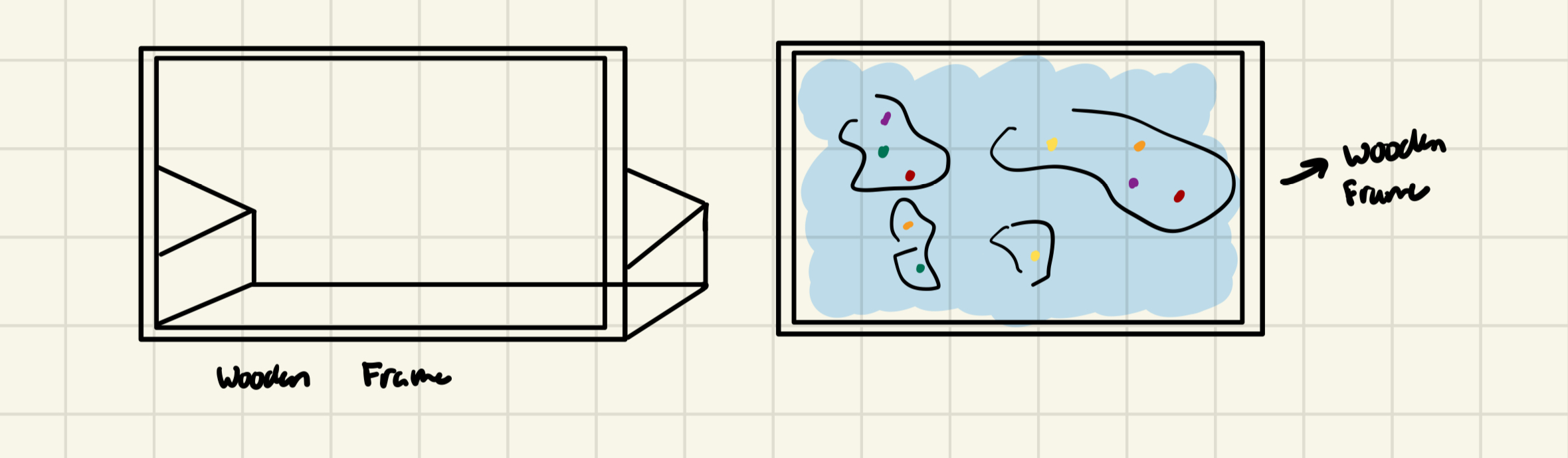
I don’t think my ideas will be too difficult to implement, so in keeping it simple I hope to truly perfect each aspect of it. However, I do still have some concerns going into it. I have yet to make any final decisions on what the software side will look like, I want it to be simple yet playful but am not exactly sure how I’d like to implement that aesthetic yet. Additionally, I originally designed a frame that stands up for users to press the buttons but after further consideration I realized they might not be able to properly push the buttons in because there is no support behind the map. My possible solutions for this are either using light sensors instead of buttons so they basically just have to hover their finger over the location, or making a 2D frame of sorts that just lays flat along the table. I think the map laying flat will be easier to implement and design so I will probably go with that as a solution but am still hesitant because I think it sacrifices a bit of the aesthetic of the overall design.
On the left is the standing up version and what the support would look like and on the right is the ‘tabletop’ design.
As I move further into the implementation stage I also want to consider the possibility of users being able to add their own songs but don’t want to get too far ahead of myself before the foundation is established.
Arduino Component
For the most part the main thing the Arduino will be dealing with is receiving the information of what location the user selects. If time permits, I’d love to create some kind of LED visual to go along with the music but that is not my priority for now. Although I was originally leaning towards using the light sensors to detect the location a user selects, I am afraid of inconsistency in the data being read because their will be so much going on at the showcase so I think the buttons will be more reliable. With that being said, the Arduino program will signal P5 when a city is chosen and then P5 will handle the rest in terms of playing the song and whatnot. A small feature I am interested in implementing as well is using the LED board display that simply writes “Welcome to [country of song’s origin” to another component.
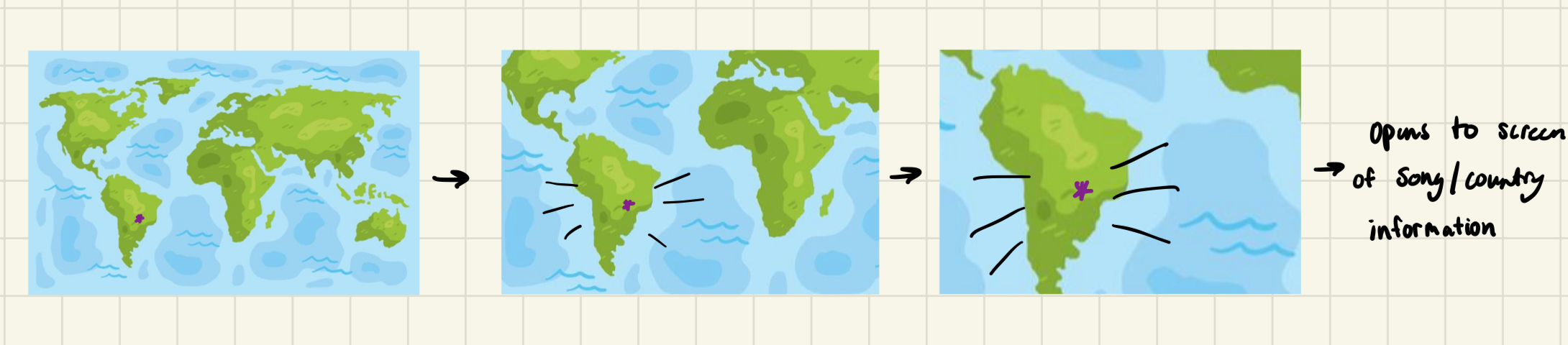
On the P5 side, I would really like to have an animation aspect of sorts that zooms in from a full map view to the specific city in order to play a song. I don’t think this will be too difficult to implement because I can just play a video, but I’m not exactly sure how I’d do it because I would need to create a different animation for each of the 10 cities which is a bit tedious. Here is a rough idea of what I mean by animation:
Once the animation plays a little information card about the song, it’s origins and the person who submitted it will play. Then, the user will be prompted to start the song/video via an on screen button and then can repeat and explore the map from there. I do not plan on playing the entire song for each video, I am thinking 20-30 seconds of the main chorus of the person who submitted it’s favorite part of the song.
P5 will be receiving the information about what button was selected from Arduino and will send a ‘current state’ flag to Arduino to prevent users from trying to select another location while a current one’s video is playing.
I have decided to work on the idea to use a box to control the platform for the hero. There will be 1 box that the user can move (physical part) that will control the platform in p5js. The project is inspired by the game “My Shadows are Bright” from GMTK game jam 2024.
For my game, the physical/arduino part will include a cardboard box that can be moved on the x, y axis by the user. Depends on the position of the box, it will be drawn on the screen in p5js in form of a platform. If the box is nearer to the front sensor (or user), it will be drawn bigger, and if it’s further away it will be smaller. This game is a puzzle game type, where the user have to move the box to get the correct size and position for the game character to move from the left side of the screen to the right side.
In terms of the story, I want to tell a story of how rejection is not always bad, sometimes it leads you to a path that is more suitable. It will be carried out using the character prince who is always rejected by the princess.
Implementation
Arduino
2 photoresistors/ultrasonic sensors: 1 in front and 1 on right hand side
1 LED to show game started
Resistors and wires
cardboards
P5js
Platform/box class
Hero class
Collision detection: detect when hero is standing on the platform and when not standing on the platform
Stages (introduction, game play, ending)
Progress
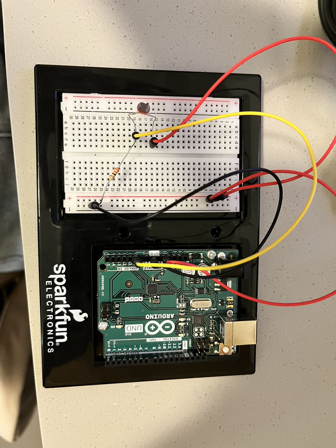
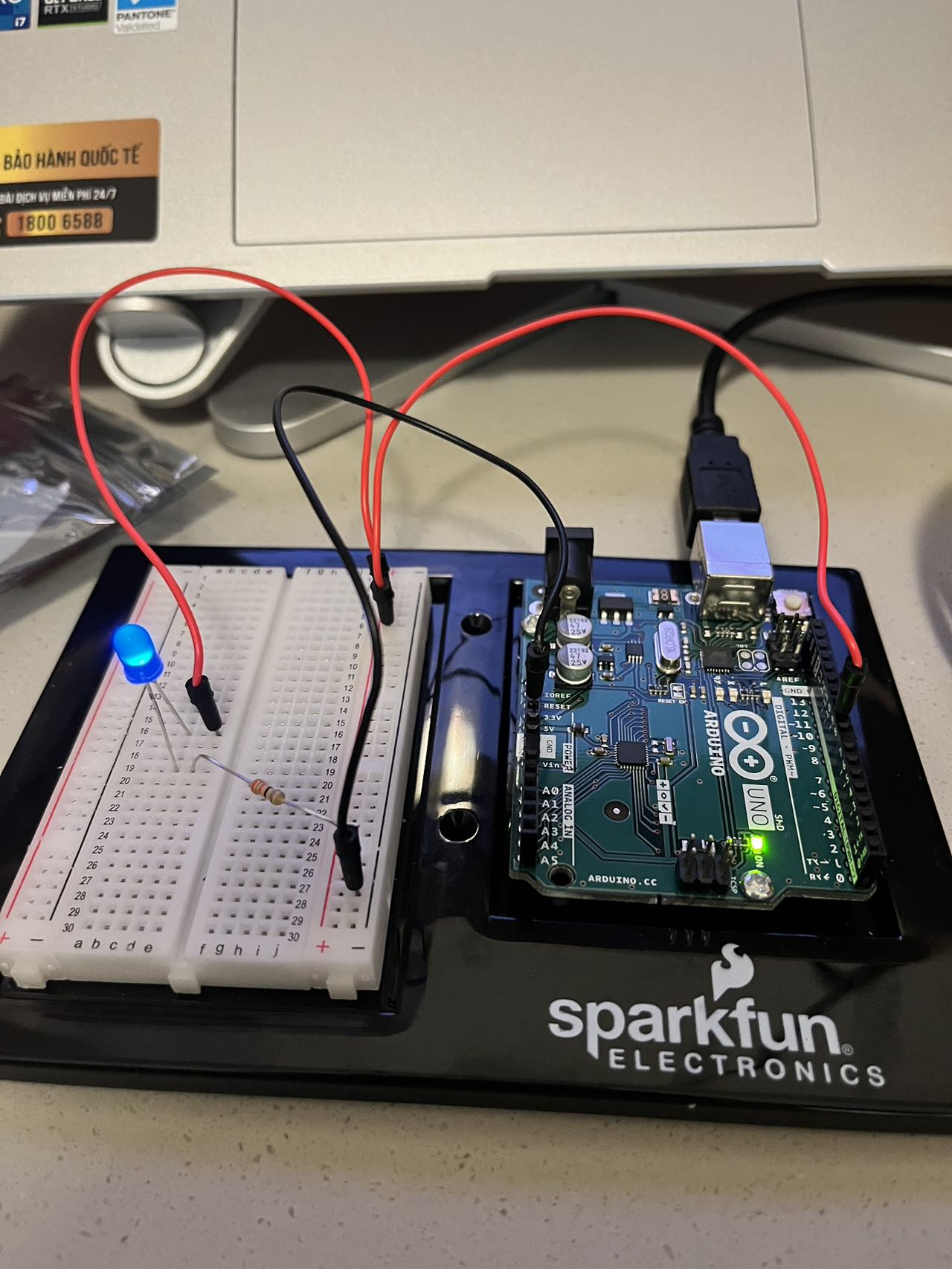
I am not sure if this project is feasible or not so I make a small prototype to see if I can use arduino to track the position of the box. In this code I get analog read value from photoresistor and draw a box based on how near or far it is from the sensor. It seems feasible so far.
For my final project, I decided to bring my midterm project to life and create controllers for the game characters that I designed. If it’s possible, I would like to make two game pads which two players will have to press physically with their feet, which then controls the two characters on the screen. The game pads would be inspired by the video game Dance Dance Revolution (DDR). In addition to the game pads, I was also thinking about adding sound effects using the beeper when the health decreases in the game, the LCD display to depict some artwork or health bar, or the LEDs to give some feedback to the players. I would like to make use of the woodshop, but if time doesn’t permit this idea, I wouldn’t mind scaling down to use the 3D printers or laser cutters.
Some Code Snippet for the Week
const int UP_BUTTON = 11;
const int DOWN_BUTTON = 10;
const int RIGHT_BUTTON = 6;
const int LEFT_BUTTON = 5;

void setup() {
  // Start serial communication at 9600 baud
  Serial.begin(9600);

  // Set button pins as input with internal pull-up resistors
  pinMode(UP_BUTTON, INPUT_PULLUP);
  pinMode(DOWN_BUTTON, INPUT_PULLUP);
  pinMode(RIGHT_BUTTON, INPUT_PULLUP);
  pinMode(LEFT_BUTTON, INPUT_PULLUP);
}

void loop() {
  // Read the state of the UP_BUTTON (HIGH = not pressed, LOW = pressed)
  int upButtonState = digitalRead(UP_BUTTON);
  int downButtonState = digitalRead(DOWN_BUTTON);
  int rightButtonState = digitalRead(RIGHT_BUTTON);
  int leftButtonState = digitalRead(LEFT_BUTTON);

  // Print the value (HIGH or LOW) to the Serial Monitor
  Serial.print(upButtonState);
  Serial.print(",");
  Serial.print(downButtonState);
  Serial.print(",");
  Serial.print(rightButtonState);
  Serial.print(",");
  Serial.println(leftButtonState);

}
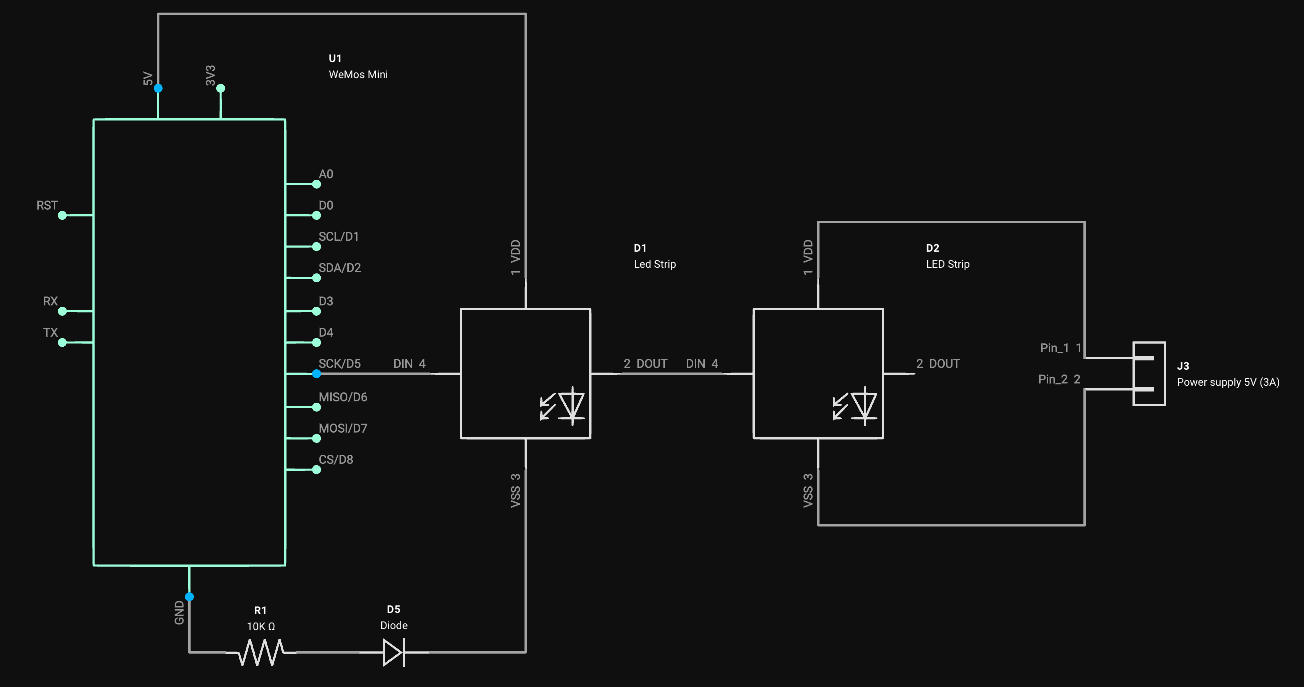
Final Concept I’m building an interactive clock that uses ping pong balls as display elements. The main feature is a hexagonal matrix made of 128 ping pong balls that will show the current time with different cool background effects which you can control from your phone. Each ball will have an addressable LED inside that can be individually controlled.
Wemos Mini (Arduino)
The Wemos Mini D1 will be the brain of the operation, handling way more than I initially planned.
Main Functions:
Connect to WiFi to get accurate time from pool.ntp.org
Control all 128 WS2812B LEDs
Handle all time calculations and display patterns
Store user settings in its memory
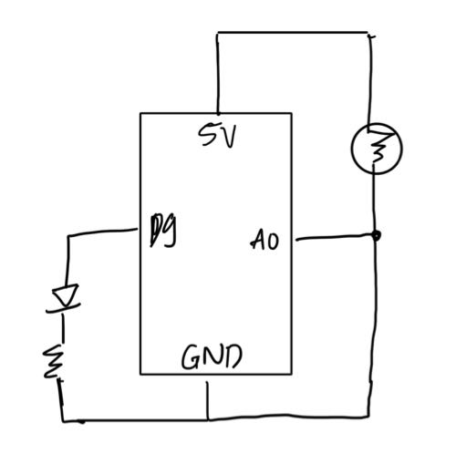
Schematic
P5.js
P5.js will serve as a configuration interface for the clock. It will only send the data entered as it is to the Wemos Mini.
Configuration options:
Font and font color
Background effect
Type (Perlin/Gradient)
Color palette
Brightness
Speed
Angle
Overall brightness of the clock
Night mode (ON/OFF)
Time server and timezone
WiFi settings
For this project I want to try hosting the P5.js sketch on the Wemos Mini, making it accessible through any web browser on the local network.This task sounds to me like it would be a very interesting one to explore.
Challenges Faced
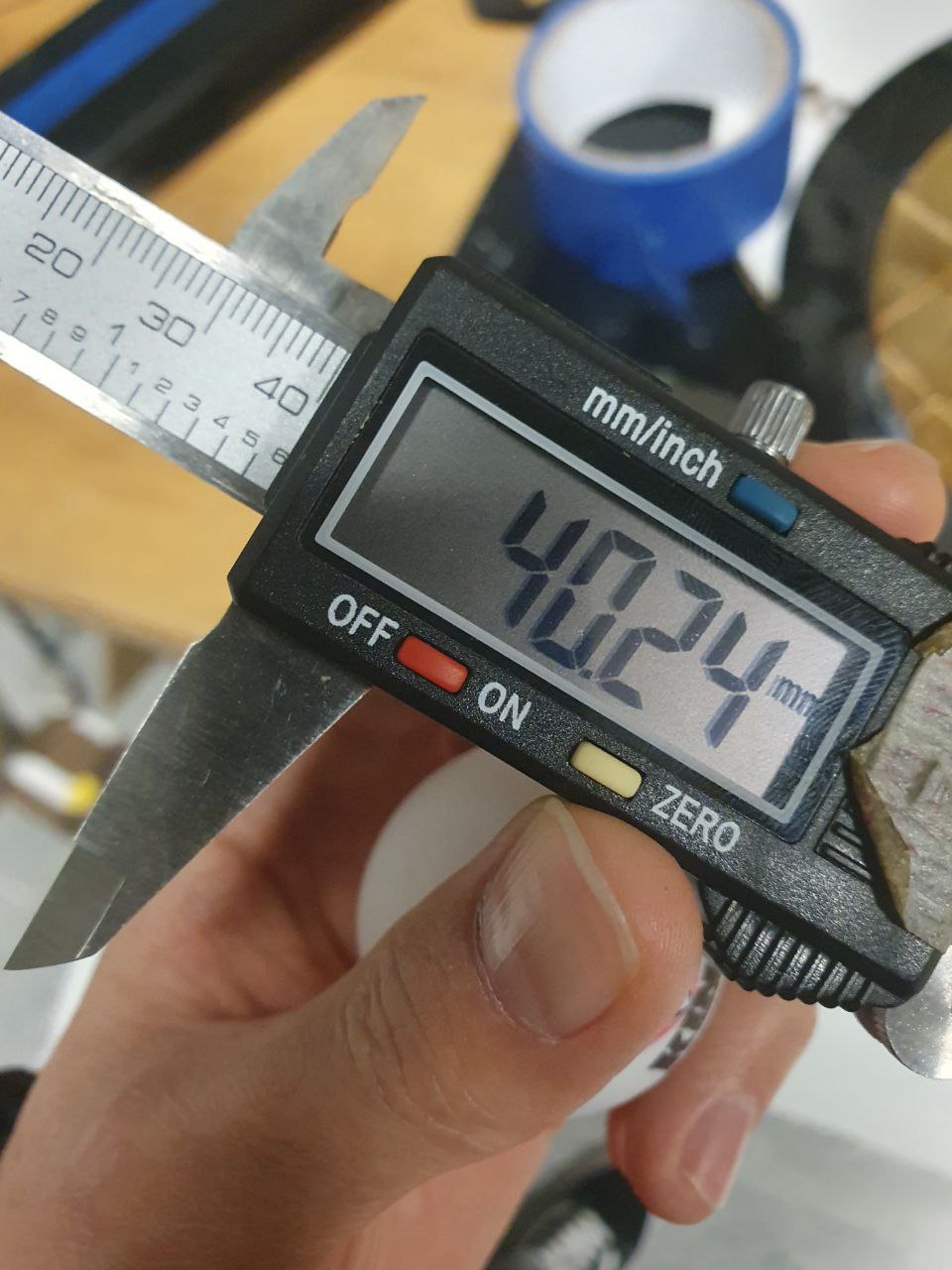
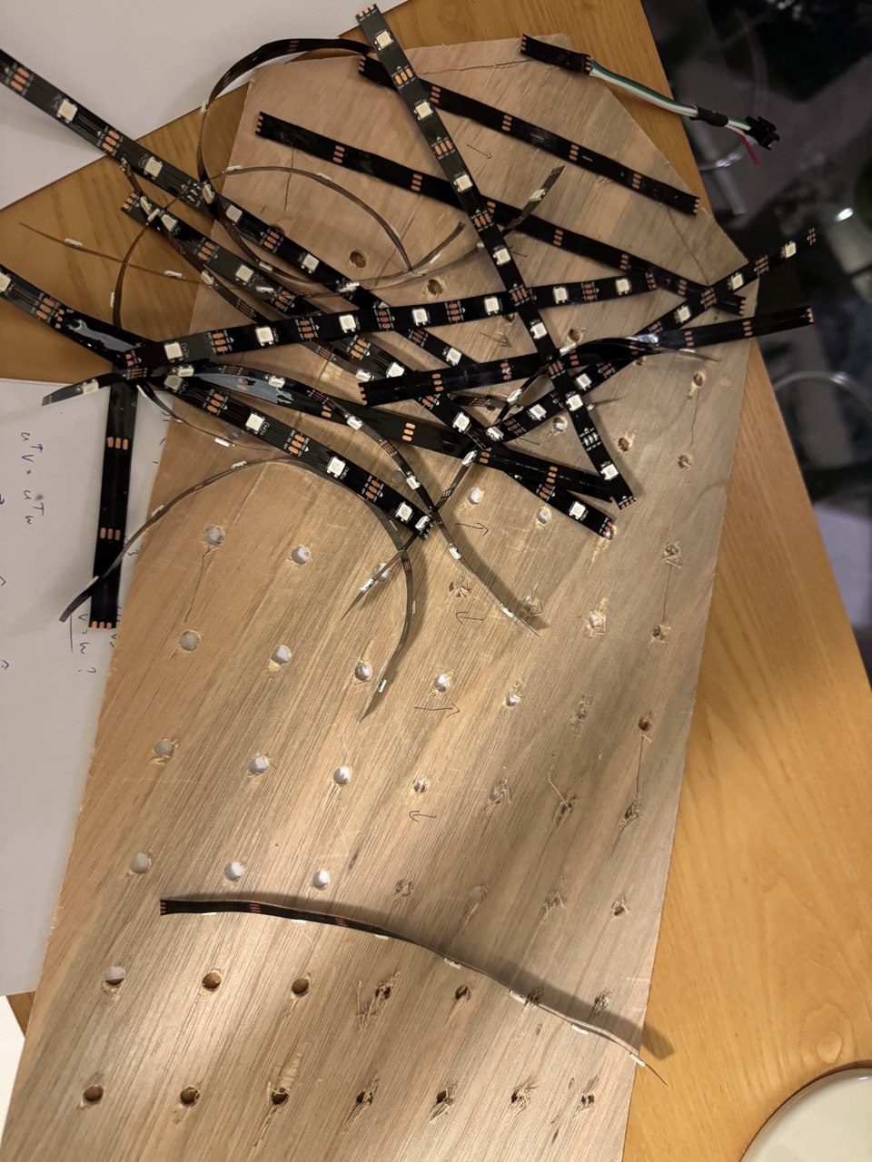
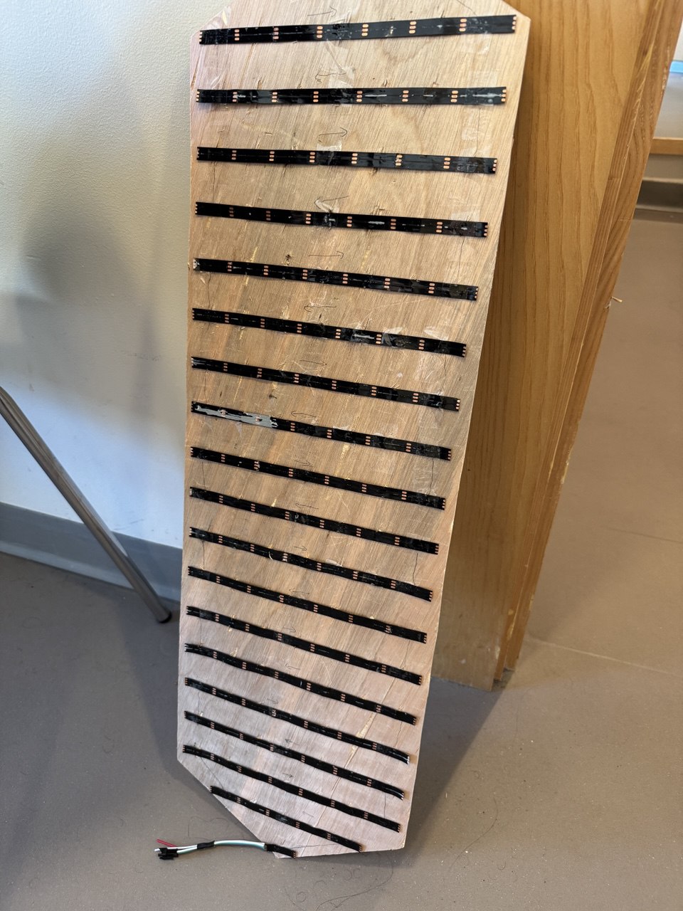
My first major hurdle came from the LED strip specifications. I got the WS2812B LED Strip rated at 30 LEDs per meter, but the actual spacing turned out to be 33.15mm instead of the expected 33.33mm per LED. This small 0.18mm difference created significant alignment issues over the full length of the strip.
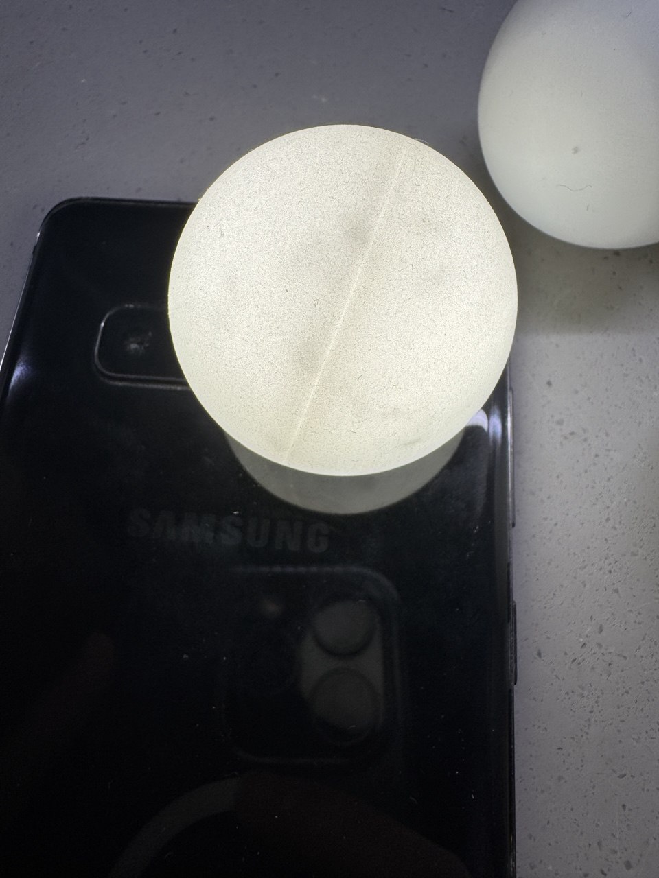
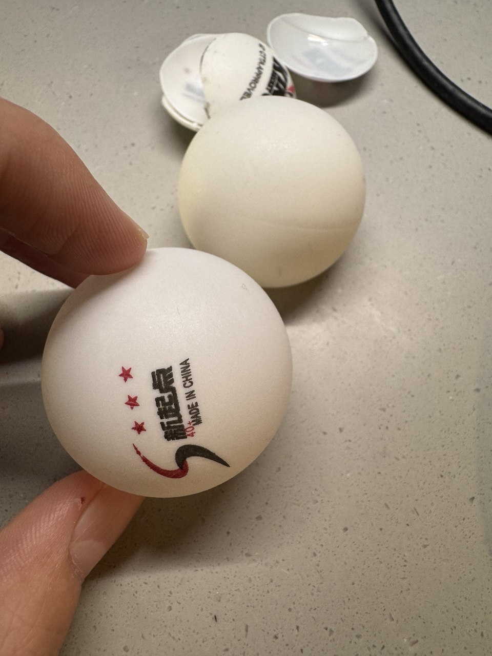
My second challenge was the ping pong balls, they weren’t quite what I expected either. Despite ordering balls without logos, each one came with a printed logo on them, which could not be rubbed off with anything, and using sandpaper would cause light diffusion. On top of that, I discovered that each ball wasn’t a single piece as I’d assumed, but actually two halves merged together. This created a visible seam when light shone through the ball.
I found myself at a crossroads: I could either align all the balls so the seams were positioned horizontally, which would make the logos unpossible to cut out because they were placed randomly on the ball, or I could prioritize hiding the logos, which would result in the seams being more visible. After some consideration, I decided to cut out the logos. They were more distracting than the seams, and I figured the uniform light would help mask the seam lines better than it would hide the printed logos.
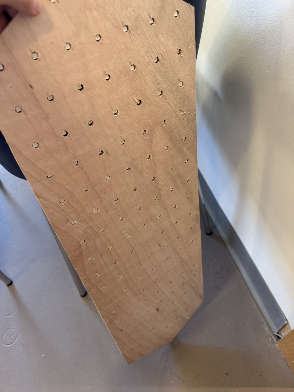
These unexpected issues with both the LEDs and the ping pong balls have forced me to rethink my entire mounting and display system. It’s been frustrating, but it’s also pushing me to come up with more creative solutions.
Next steps
Set up the Wemos Mini web server
Create the P5.js configuration interface
Design the LED patterns for numbers
Build a proper mounting system that accounts for actual LED spacing
Test WiFi connectivity and time synchronization
Despite these setbacks, I’m still excited about this project. Each challenge is teaching me something new, and I’m looking forward to seeing how the final product turns out.
I have a bit of a better idea now for my final project (though I’m not ruling out the possibility of doing something completely different 😅). I’m not really sure how best to describe it, but simply put, you have the power to manipulate objects with your hands, and you use to protect yourself and fight against a villain, who you must also chase down (a bit of a reference to my midterm).
# Design Description
Arduino:Inputs:
Pressure sensor (inside of a stress ball), for detecting when the player closes their hand.
Capacitive touch sensor strip, as a control for firing.
Some game state info (from p5)
Outputs:
Neopixel (addressable LED strip)
Send values of pressure sensor and touch sensor to p5.
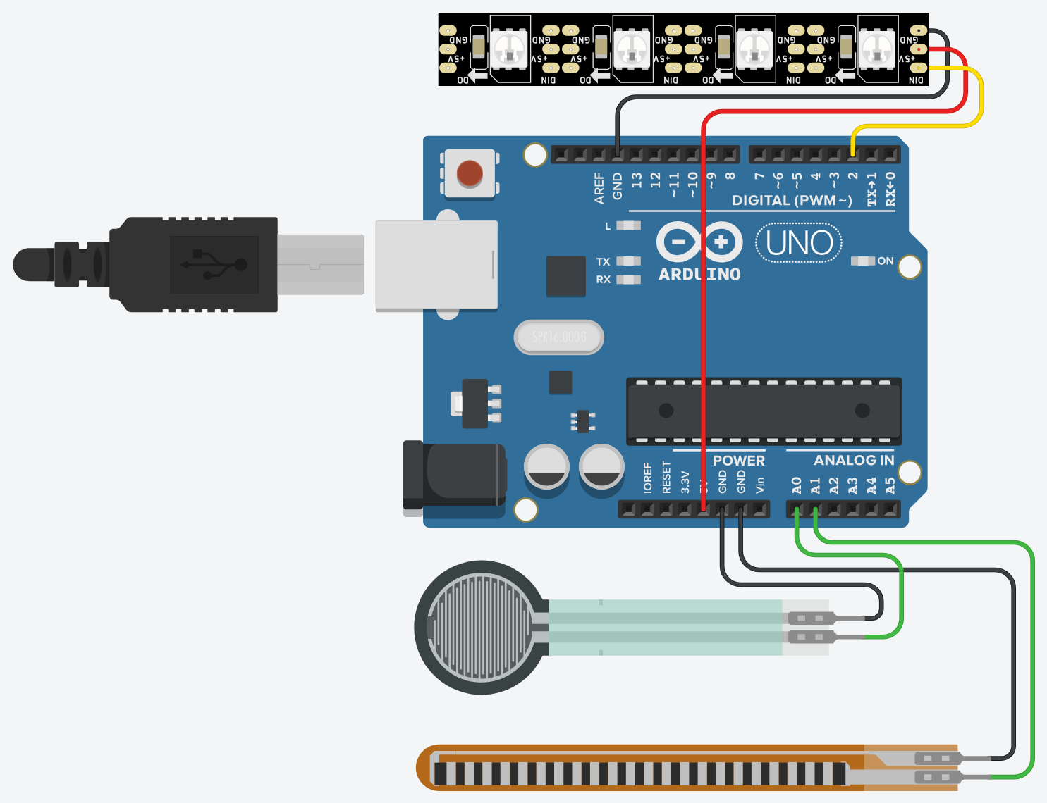
Circuit View:
Note: I used a flex sensor in place of the touch sensor as that wasn’t available right now.
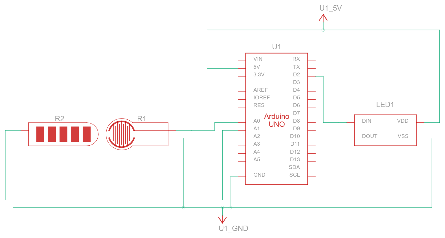
Schematic:
Note: I used a flex sensor in place of the touch sensor as that wasn’t available right now.
p5:Inputs:
MoveNet pose detection, to get angle of the player’s hand in relation with the screen.
Pressure sensor and touch sensor values from Arduino.
For my final project, I want to incorporate and showcase my interests. One of these interests of mines are penguins. Therefore, I have settled on making an interactive game called ‘Pingu Pounce’. Pingu Pounce is essentially an exhilarating game where players help a plucky penguin fly through icy platforms. With simple physical controls, players will use them to make their penguin leap from one slippery platform to the next, aiming to climb as high as possible while avoiding obstacles like sharp platforms.
“make something that uses only one sensor on Arduino and makes the ellipse in p5 move on the horizontal axis, in the middle of the screen, and nothing on Arduino is controlled by p5”
The following code was utilized for this particular exercise:
let sensorValue = 0; // To store the sensor value from Arduino

function setup() {
  createCanvas(640, 480);
  textSize(18);
}

function draw() {
  background(220);

  if (!serialActive) {
    text("Press Space Bar to select Serial Port", 20, 30);
  } else {
    text("Connected", 20, 30);

    // Display the sensor value
    text('Sensor Value: ' + sensorValue, 20, 50);

    // Map the sensor value to the horizontal position of the ellipse
    let ellipseX = map(sensorValue, 0, 1023, 0, width);

    // Draw the ellipse in the middle of the canvas vertically
    fill(255, 0, 0);
    ellipse(ellipseX, height / 2, 50, 50);
  }
}

function keyPressed() {
  if (key == " ") {
    setUpSerial(); // Start the serial connection
  }
}

// This function is called by the web-serial library
function readSerial(data) {
  if (data != null) {
    let fromArduino = trim(data); // Trim any whitespace
    if (fromArduino !== "") {
      sensorValue = int(fromArduino); // Convert the sensor value to an integer
    }
  }
}
The following code was used in the Arduino IDE for this exercise:
// make something that uses only one sensor  on Arduino and makes the ellipse in p5 move on the horizontal axis,
// in the middle of the screen, and nothing on arduino is controlled by p5

int sensorPin = A0; // Single sensor connected to A0

void setup() {
  Serial.begin(9600);
}

void loop() {
  int sensorValue = analogRead(sensorPin); // Read sensor value
  Serial.println(sensorValue); // Send sensor value to p5.js
  delay(50); // Short delay for stability
}
Exercise 2:
“make something that controls the LED brightness from p5”
The following code was used to make this exercise come to fruition:
let brightness = 0; // Brightness value to send to Arduino

function setup() {
  createCanvas(640, 480);
  textSize(18);

  // Create a slider to control brightness
  slider = createSlider(0, 255, 0);
  slider.position(20, 50);
}

function draw() {
  background(220);

  if (!serialActive) {
    text("Press Space Bar to select Serial Port", 20, 30);
  } else {
    text("Connected", 20, 30);

    // Display brightness value
    text("Brightness: " + brightness, 20, 90);

    // Update brightness from the slider
    brightness = slider.value();

    // Send brightness to Arduino
    writeSerial(brightness + "\n");

  }
}

function keyPressed() {
  if (key == " ") {
    setUpSerial(); // Start the serial connection
  }
}

function readSerial(data) {
  if (data != null) {
    let fromArduino = trim(data); // Trim whitespace
    brightness = int(fromArduino); // Parse data into an integer
  }
}
The following Arduino code was used for this particular exercise:
//make something that controls the LED brightness from p5

int ledPin = 3;

void setup() {
  Serial.begin(9600);
  pinMode(ledPin, OUTPUT);
}

void loop() {
  if (Serial.available()) {
    int brightness = Serial.parseInt();
    if (Serial.read() == '\n') {
      brightness = constrain(brightness, 0, 255);
      analogWrite(ledPin, brightness);
      Serial.println(brightness); // Send brightness to p5.js
    }
  }
}
Exercise 3:
The following code is an alteration of professor Aaron Sherwood’s code which was used for this exercise:
let velocity;
let gravity;
let position;
let acceleration;
let wind;
let drag = 0.99;
let mass = 50;

let windSensorValue = 0; // Value from the wind sensor
let connectButton; // Button for connecting to the serial port

function setup() {
  createCanvas(640, 360);
  noFill();

  position = createVector(width / 2, 0); // Initial position of the ball
  velocity = createVector(0, 0); // Initial velocity
  acceleration = createVector(0, 0); // Initial acceleration
  gravity = createVector(0, 0.5 * mass); // Gravity force
  wind = createVector(0, 0); // Initial wind force

  // Create a button to initiate the serial connection
  connectButton = createButton("Connect to Serial");
  connectButton.position(10, 10);
  connectButton.mousePressed(setUpSerial); // Trigger serial connection on button press
}

function draw() {
  background(255);

  if (!serialActive) {
    text("Click 'Connect to Serial' to start", 20, 50);
    return; // Exit the draw loop until the serial connection is established
  }

  // Map wind sensor value to wind force (affects horizontal movement)
  wind.x = map(windSensorValue, 0, 1023, -1.5, 1.5); // Adjust force range as needed

  // Apply forces
  applyForce(wind); // Apply wind force
  applyForce(gravity); // Apply gravity force

  // Update velocity and position
  velocity.add(acceleration);
  velocity.mult(drag); // Apply drag (friction)
  position.add(velocity);
  acceleration.mult(0); // Reset acceleration

  // Ball bounce logic (vertical boundary)
  if (position.y > height - mass / 2) {
    position.y = height - mass / 2; // Place the ball on the ground
    velocity.y *= -0.9; // Reverse and dampen vertical velocity

    // Notify Arduino to toggle the LED when the ball touches the ground
    writeSerial("1\n"); // Send '1' to Arduino
  } else {
    // Ensure the LED is off when the ball is not touching the ground
    writeSerial("0\n"); // Send '0' to Arduino
  }

  // Draw the ball
  ellipse(position.x, position.y, mass, mass);
}

function applyForce(force) {
  // Newton's 2nd law: F = M * A -> A = F / M
  let f = p5.Vector.div(force, mass); // Scale force by mass
  acceleration.add(f); // Add force to acceleration
}

// Reset the ball to the top of the screen when the space key is pressed
function keyPressed() {
  if (key === " ") {
    position.set(width / 2, 0); // Reset position to top center
    velocity.set(0, 0); // Reset velocity to zero
    mass = random(15, 80); // Randomize mass
    gravity.set(0, 0.5 * mass); // Adjust gravity based on new mass
  }
}

// Serial communication: Read sensor value from Arduino
function readSerial(data) {
  if (data != null) {
    let trimmedData = trim(data);
    if (trimmedData !== "") {
      windSensorValue = int(trimmedData); // Read wind sensor value
    }
  }
}
The following code was used in the Arduino IDE to bring this to life:
//gravity wind example
int ledPin = 2;     // Pin connected to the LED
int windPin = A0;   // Analog pin for the potentiometer (A0)

void setup() {
  Serial.begin(9600);        // Start serial communication
  pinMode(ledPin, OUTPUT);   // Set the LED pin as an output
  digitalWrite(ledPin, LOW); // Turn the LED off initially
}

void loop() {
  // Read the analog value from the potentiometer
  int windValue = analogRead(windPin);

  // Send the wind value to p5.js over serial
  Serial.println(windValue);

  // Check if a signal is received from p5.js for the LED
  if (Serial.available()) {
    char command = Serial.read(); // Read the signal from p5.js
    if (command == '1') {
      digitalWrite(ledPin, HIGH); // Turn on the LED when the ball touches the ground
    } else if (command == '0') {
      digitalWrite(ledPin, LOW);  // Turn off the LED
    }
  }

  delay(5); // Small delay for stability
}
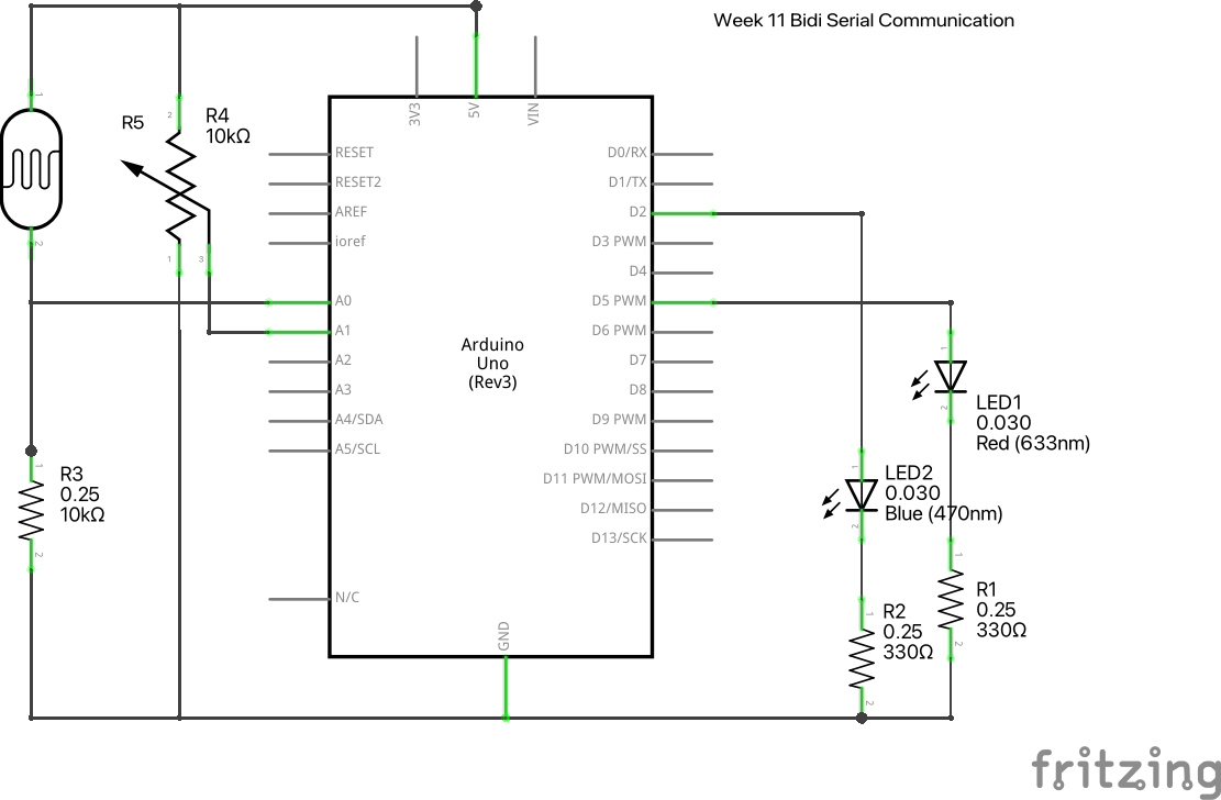
The following schematic was used for all 3 of the exercises with slight moderations, provided in class:
Drawing an ellipse and making it move horizontally based on photoresistor
Code:
let x=0;

function setup() {
  createCanvas(400,400);
  textSize(18);
}

function draw() {
  if (serialActive){
    background("white");
    ellipse(map(x,0,1023,0,400),height/2,50,50);
  }else{
    background("white");
    console.log("not connected");
  }
}

function keyPressed() {
  if (key == " ") {
    // important to have in order to start the serial connection!!
    setUpSerial();
  }
}

function readSerial(data) {

  if (data != null) {
    x = int(data);
  }else{
    x = 0;
  }
}

//Arduino code
// void setup() {
//     Serial.begin(9600);
//     pinMode(A0, INPUT);
// }

// void loop() {
//   Serial.println(analogRead(A0));
// }
Exercise 2
Increase the brightness of the LED with mouse click
Code:
let bright=0;

function setup() {
  createCanvas(400,400);
  textSize(18);
}

function draw() {
  if (serialActive){
    background("white");
    text(bright,10,10);
  }else{
    background("white");
    console.log("not connected");
  }
}

function keyPressed() {
  if (key == " ") {
    // important to have in order to start the serial connection!!
    setUpSerial();
  }
}

function mousePressed(){
  if(serialActive){
    bright+=1;
    writeSerial(bright);
  }

}
function readSerial(data) {

}

//Arduino code
// int brightness;
// void setup() {
//     Serial.begin(9600);
//     pinMode(9, OUTPUT);
// }

// void loop() {
//   brightness = Serial.parseInt();
//   analogWrite(9,brightness);
// }
Exercise 3
Turning on LED when the ball bounces and use photoresistor to control wind movement
Circuit
Video:
Code:
let velocity;
let gravity;
let position;
let acceleration;
let wind;
let drag = 0.99;
let mass = 50;
let bounce = 0;

function setup() {
  createCanvas(640, 360);
  noFill();
  position = createVector(width/2, 0);
  velocity = createVector(0,0);
  acceleration = createVector(0,0);
  gravity = createVector(0, 0.5*mass);
  wind = createVector(0,0);
}

function draw() {
  background(255);
  if(!serialActive){
    console.log("PRESS a TO CONNECT");
  }
   else{
    applyForce(wind);
    applyForce(gravity);
    velocity.add(acceleration);
    velocity.mult(drag);
    position.add(velocity);
    acceleration.mult(0);
    ellipse(position.x,position.y,mass,mass);
    if (position.y > height-mass/2) {
        velocity.y *= -0.9;  // A little dampening when hitting the bottom
        position.y = height-mass/2;
        bounce = 1;
      }else{
        bounce = 0;
      }

  }
}

function applyForce(force){
  // Newton's 2nd law: F = M * A
  // or A = F / M
  let f = p5.Vector.div(force, mass);
  acceleration.add(f);
}

function keyPressed(){
  if (keyCode==LEFT_ARROW){
    wind.x=-1;
  }
  if (keyCode==RIGHT_ARROW){
    wind.x=1;
  }
  if (key==' '){
    mass=random(15,80);
    position.y=-mass;
    velocity.mult(0);
  }
   if (key == "a") {
    // important to have in order to start the serial connection!!
    setUpSerial();
  }
}
function readSerial(data) {
  if (data != null) {
        console.log(data);
        wind.x = map(int(data), 0, 1023, -2, 2);
        writeSerial(bounce + '\n');
  }
}

//Arduino code
// int bounce;
// void setup() {
//   Serial.begin(9600);
//   pinMode(9,OUTPUT);
//   while (Serial.available() <= 0) {
//     Serial.println("0"); // send a starting message
//   }
// }

// void loop() {
//   while(Serial.available()){

//     bounce = Serial.parseInt();
//     if (Serial.read() == '\n') {
//       digitalWrite(9,bounce);

//     }

//   }
//   int sensor = analogRead(A1);
//   Serial.println(sensor);
//   // Serial.println(analogRead(A0));

// }
1. Make an ellipse in p5 move on the horizontal axis using only one sensor. Video Link
int leftLedPin = 4;
int rightLedPin = 6;
const int trigPin = 10;
const int echoPin = 9;

void setup() {
  // Start serial communication at 9600 baud
  Serial.begin(9600);

  // Set up the LED and ultrasonic sensor pins
  pinMode(LED_BUILTIN, OUTPUT);
  pinMode(leftLedPin, OUTPUT);
  pinMode(rightLedPin, OUTPUT);
  pinMode(trigPin, OUTPUT);
  pinMode(echoPin, INPUT);

  // Blink LEDs to check wiring
  digitalWrite(leftLedPin, HIGH);
  digitalWrite(rightLedPin, HIGH);
  delay(200);
  digitalWrite(leftLedPin, LOW);
  digitalWrite(rightLedPin, LOW);
}

void loop() {
  // Check if there is data available from p5.js
  if (Serial.available()) {
    int left = Serial.parseInt();   // Get the left LED value
    int right = Serial.parseInt();  // Get the right LED value

    // Update LEDs based on values from p5.js
    digitalWrite(leftLedPin, left);
    digitalWrite(rightLedPin, right);

    // Clear any remaining characters in the serial buffer (such as '\n')
    Serial.read();
  }

  // Trigger the ultrasonic sensor
  digitalWrite(trigPin, LOW);
  delayMicroseconds(2);
  digitalWrite(trigPin, HIGH);
  delayMicroseconds(10);
  digitalWrite(trigPin, LOW);

  // determine the time for the echo
  long timeTraveled = pulseIn(echoPin, HIGH);

  // the distance in centimeters
  int distance = timeTraveled * 3.4/2;

  int sensor = analogRead(A1);

  // Send the distance value to p5.js
  Serial.print(sensor);
  Serial.print(",");
  Serial.println(distance);

  delay(100);
}
const int blue_LED = 4;
const int red_LED = 6;

void setup() {
  // put your setup code here, to run once:
  Serial.begin(9600);

  // Initalization of LED pins
  pinMode(blue_LED, OUTPUT);
  pinMode(red_LED, OUTPUT);

  // Blink LEDs to check wiring
  digitalWrite(blue_LED, HIGH);
  digitalWrite(red_LED, HIGH);
  delay(200);
  digitalWrite(blue_LED, LOW);
  digitalWrite(red_LED, LOW);

}

void loop() {
  // put your main code here, to run repeatedly:
  Serial.println(0);
  if (Serial.available()) {
    int left = Serial.parseInt();   // Get the left LED value
    int right = Serial.parseInt();  // Get the right LED value

    // Update LEDs based on values from p5.js
    digitalWrite(blue_LED, left);
    digitalWrite(red_LED, right);

    // removes remaining characters in the serial buffer
  }
  Serial.read();
  delay(100);
}
const int LED_pin = 6;

void setup() {
  // put your setup code here, to run once:
  Serial.begin(9600);
  pinMode (LED_pin, OUTPUT);

  // digitalWrite(LED_pin, HIGH);
  // delay(200);
  // digitalWrite(LED_pin, LOW);

}

void loop() {
  // put your main code here, to run repeatedly:
  if (Serial.available()) {
    int LED_value = Serial.parseInt();   // Get the LED value

    // Update LEDs based on values from p5.js
    digitalWrite(LED_pin, LED_value);

    // Clear any remaining characters in the serial buffer (such as '\n')
    Serial.read();
  }

  int sensor = analogRead(A0);
  Serial.println(sensor);
}

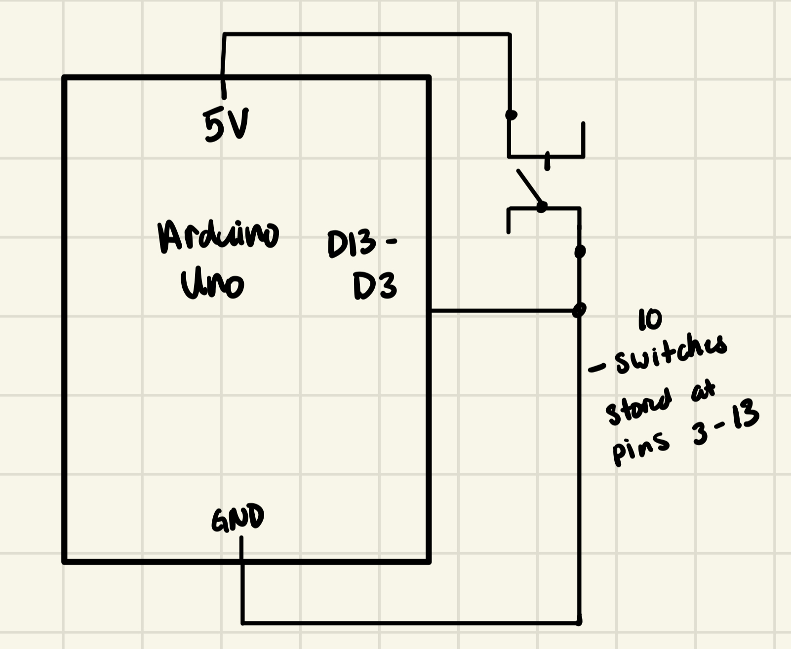 I did not include the LCD display in this schematic because I’m not sure how I’d balance those pins with what I need for the switches so I am temporarily pausing that idea. I will see if I can split half of the switched on analog and the other half on digital since LCD needs to be on digital pins.