Week 10 – Echoes of Light

Concept

Our project, Ibrahim and I, “Echoes of Light,” emerged from a shared interest in using technology to create expressive, interactive experiences. Inspired by the way sound changes with distance, we aimed to build a musical instrument that would react naturally to light and proximity. By combining a photoresistor and distance sensor, we crafted an instrument that lets users shape sound through simple gestures, turning basic interactions into an engaging sound experience. This project was not only a creative exploration but also a chance for us to refine our Arduino skills together.

Materials Used

  • Arduino Uno R3
  • Photoresistor: Adjusts volume based on light levels.
  • Ultrasonic Distance Sensor (HC-SR04): Modifies pitch according to distance from an object.
  • Piezo Buzzer/Speaker: Outputs the sound with controlled pitch and volume.
  • LED: Provides an adjustable light source for the photoresistor.
  • Switch: Toggles the LED light on and off.
  • Resistors: For the photoresistor and LED setup.
  • Breadboard and Jumper Wires

    Code

The code was designed to control volume and pitch through the analog and digital inputs from the photoresistor and ultrasonic sensor. The complete code, as documented in the previous sections, includes clear mappings and debugging lines for easy tracking.

// Define pins for the components
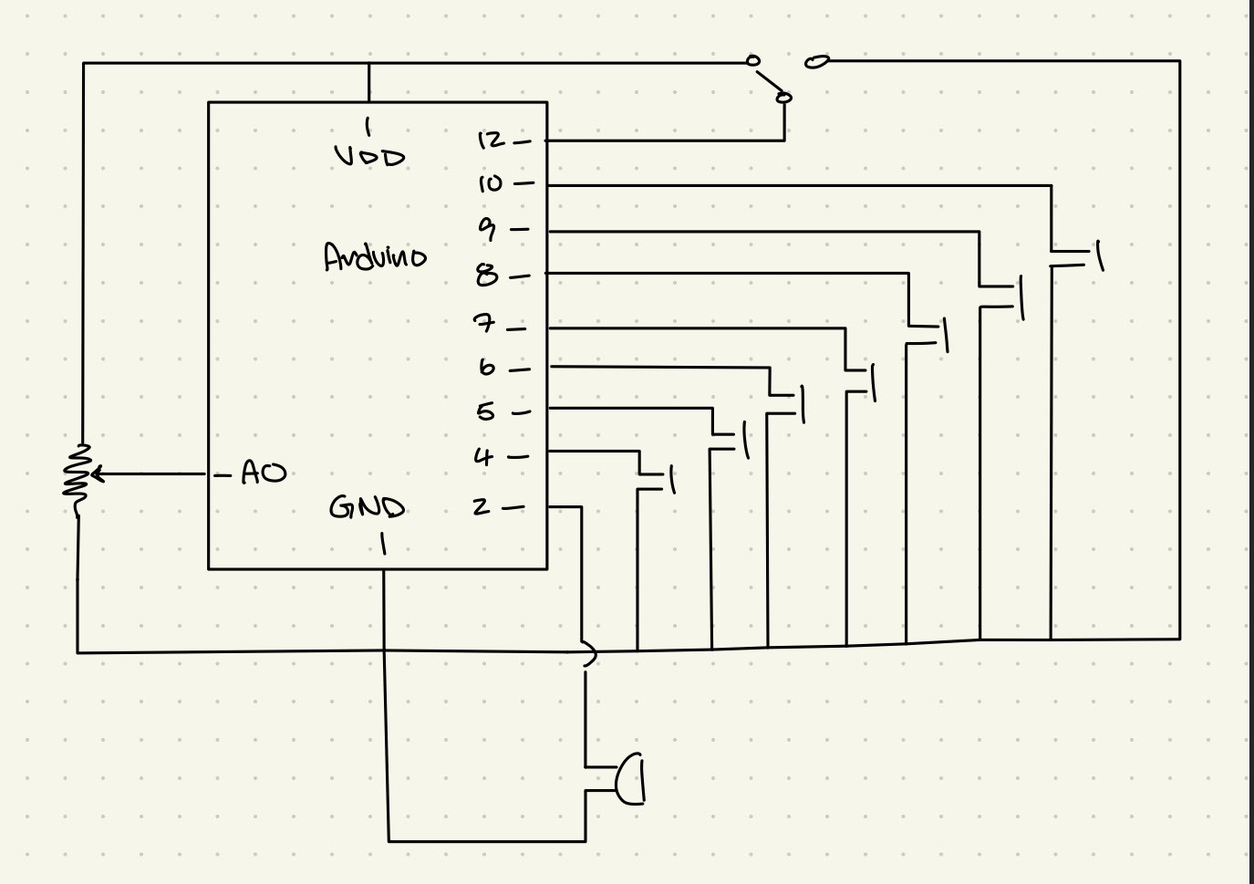
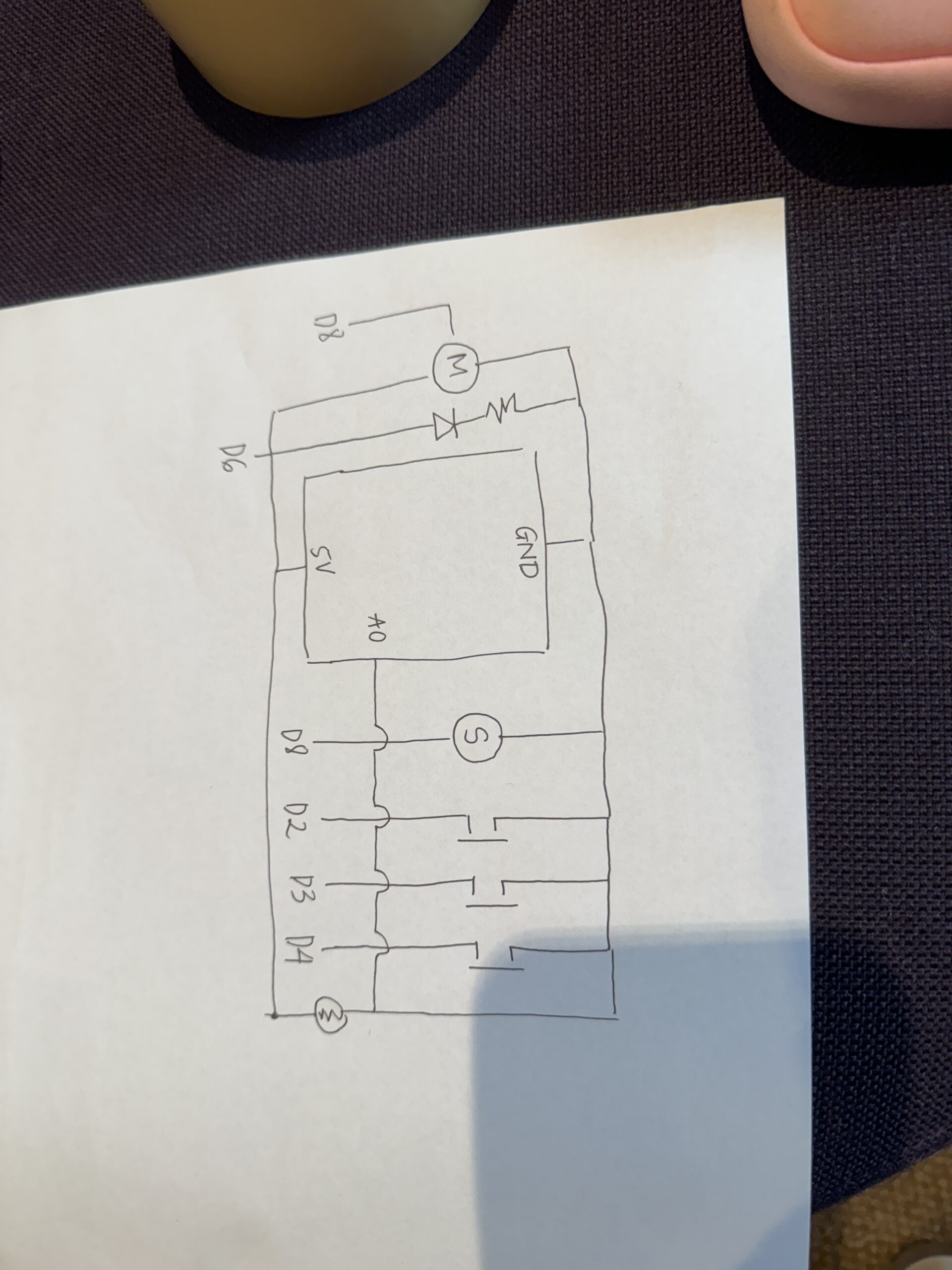
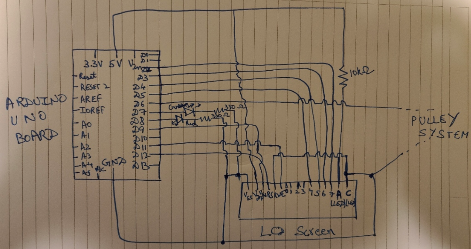
const int trigPin = 5;               // Trigger pin for distance sensor
const int echoPin = 6;              // Echo pin for distance sensor
const int speakerPin = 10;           // Speaker PWM pin (must be a PWM pin for volume control)
const int ledPin = 2;                // LED pin
const int switchPin = 3;             // Switch pin
const int photoResistorPin = A0;     // Photoresistor analog pin

// Variables for storing sensor values
int photoResistorValue = 0;
long duration;
int distance;

void setup() {
  Serial.begin(9600);                // Initialize serial communication for debugging
  pinMode(trigPin, OUTPUT);          // Set trigger pin as output
  pinMode(echoPin, INPUT);           // Set echo pin as input
  pinMode(speakerPin, OUTPUT);       // Set speaker pin as output (PWM)
  pinMode(ledPin, OUTPUT);           // Set LED pin as output
  pinMode(switchPin, INPUT_PULLUP);  // Set switch pin as input with pull-up resistor
}

void loop() {
  // Check if switch is pressed to toggle LED
  if (digitalRead(switchPin) == LOW) {
    digitalWrite(ledPin, HIGH);      // Turn LED on
  } else {
    digitalWrite(ledPin, LOW);       // Turn LED off
  }

  // Read photoresistor value to adjust volume
  photoResistorValue = analogRead(photoResistorPin);
  
  // Map photoresistor value to a range for volume control (0-255 for PWM)
  // Higher light level (LED on) -> lower photoresistor reading -> higher volume
  int volume = map(photoResistorValue, 1023, 0, 0, 255); // Adjust mapping for your setup

  // Measure distance using the ultrasonic sensor
  digitalWrite(trigPin, LOW);
  delayMicroseconds(2);
  digitalWrite(trigPin, HIGH);
  delayMicroseconds(10);
  digitalWrite(trigPin, LOW);
  
  duration = pulseIn(echoPin, HIGH);
  
  // Calculate distance in cm
  distance = duration * 0.034 / 2;

  // Set frequency based on distance in the range of 2-30 cm
  int frequency = 0;
  if (distance >= 2 && distance <= 30) {
    frequency = map(distance, 1, 100, 20000, 2000); // Closer = higher pitch, farther = lower pitch
    tone(speakerPin, frequency);
    analogWrite(speakerPin, volume);  // Apply the volume based on photoresistor reading
  } else {
    noTone(speakerPin);  // Silence the speaker if the distance is out of range
  }

  // Debugging output
  Serial.print("Photoresistor: ");
  Serial.print(photoResistorValue);
  Serial.print("\tVolume: ");
  Serial.print(volume);
  Serial.print("\tDistance: ");
  Serial.print(distance);
  Serial.print(" cm\tFrequency: ");
  Serial.println(frequency);

  delay(100); // Short delay for sensor readings
}

Video Demonstration

In our video demonstration, we showcase how the instrument responds to changes in light and proximity. We toggle the LED to adjust volume and move a hand closer or farther from the ultrasonic sensor to change pitch, demonstrating the instrument’s sensitivity and interactive potential.

Week10

Reflections

The project successfully combines multiple sensors to create a reactive sound device. The integration of volume and pitch control allows for intuitive, responsive sound modulation, achieving our goal of designing an engaging, interactive instrument.

Improvements:
To improve this instrument, we would enhance the melody range, creating a more refined and versatile sound experience. This could involve using additional sensors or more sophisticated sound generation methods to provide a broader tonal range and a richer melody.

Week 10: Musical Instrument

Concept

For this week’s assignment we spent a lot of time brainstorming ideas and developing different components of the instrument. Originally, we considered a light sensor activated lullaby machine (at night it plays a lullaby and an alarm in the morning) but weren’t sure if that actually constituted an instrument. Therefore, we decided to keep it more straightforward with an electric keyboard design that you can adjust the speed or “consistency” of the notes playing.

Materials
  • Arduino Uno
  • Jumper wires
  • 7 button switches
  • Speaker
  • SPST Switch
  • Potentiometer
Schematic

Design

This project’s two main components are 7 buttons to play the notes and a potentiometer to control the speed of the notes playing. The green button to the left (closest to our potentiometer) represents middle C and then each button plays the consecutive note going up that scale. In our design, we also implemented a an SPST switch to control whether or not you could play anything on it, with the intention of mimicking an electric keyboard’s power button. A unique component to our design is the fact that we used both of our Arduino breadboards in order to better organize and manage the aesthetics of the design. Additionally, by still using one actual Arduino Uno we were able to avoid any complications with synching the information which was convenient in terms of time efficiency.

On the implementation side our biggest challenge was getting the volume to change with the adjustments of the potentiometer. After a bit of troubleshooting and heading back to the drawing board we decided to switch our original play and allow the potentiometer to control the speed of the notes. We intended to recycle as much code as we could from class and ultimately ended up use components from both Arduino’s tone() and button example codes that were reviewed in class. After switching between trying to change the pitch, speed, and volume of the notes with the potentiometer we decided on speed simply because we felt that the other adjustments weren’t noticeable enough for our intended purpose.

Code
#include "pitches.h"
 
// button pins
const int B_key = 4; 
const int A_key = 5;
const int G_key = 6; 
const int F_key = 7;
const int E_key = 8;
const int D_key = 9; 
const int C_key = 10; 
 
const int SWITCH_PIN = 12;  // switch pin
const int BUZZER_PIN = 2; // buzzer pin
const int POT_PIN = A0; // potentiometer pin 
 
// notes
int melody[] = {
  NOTE_B5, NOTE_A5, NOTE_G4, NOTE_F4, NOTE_E4, NOTE_D4, NOTE_C4
};
 
// Array for button pins
int buttonPins[] = { A_key, B_key, C_key, D_key, E_key, F_key, G_key };
 
void setup() { // initalization of the buttons, buzzer, and switch pins 
  for (int i = 0; i < 7; i++) {
    pinMode(buttonPins[i], INPUT_PULLUP); // sets button pins as inputs with internal pull-up resistors
  }
 
  pinMode(BUZZER_PIN, OUTPUT); // sets the buzzer pin as an output
  pinMode(SWITCH_PIN, INPUT_PULLUP);  // sets switch as inputs with internatinoal pull-up resistors
}
 
void loop() {
  int switchState = digitalRead(SWITCH_PIN);    // reads the state of the switch
  int potValue = analogRead(POT_PIN);   // reads the potentiometer value (0-1023)
 
  int speedDelay = map(potValue, 0, 1023, 50, 500);  // maps potentiometer value to speed delay range (50-500 ms)
 
  // if the switch is HIGH the button functionality is enabled
  if (switchState == HIGH) {
    // continously checks each button state
    for (int i = 0; i < 7; i++) {
      int buttonState = digitalRead(buttonPins[i]);
        
      // if the button is pressed,  play the corresponding note
      if (buttonState == LOW) {
        tone(BUZZER_PIN, melody[i], 200); // play note for 200ms
        delay(speedDelay); // speed delay based on the position/ value of the potentiometer 
      }
    }
  }
  delay(50);
}


Final Project music.mov – Google Drive

Conclusion and Reflection

All in all, we are both rather pleased with the outcome of this weeks assignment. With it being our first assignment working with another person, it was an interesting opportunity to compare techniques in regards to simpler things like breadboard organization or schematic design preferences. We were able to use both of our strengths in different ways and support each other in areas that we were weaker. In terms of future developments we had a few smaller ideas such as adding LEDs to correspond with the keys, or allowing the user to control the pitch of the notes. Looking at the bigger picture, we even discussed what it would look like to allow the user to choose what kind of electric keyboard sounds they wanted to play (going beyond the use of the speakers we have). Although our project is rather simple, we were truly tested when it came to debugging our code but really appreciated the experience of going at it together.

Week 10 Reading Response

In the article A Brief Rant on the Future of Interaction Design, Bret Victor critiques the current state of interactive design by highlighting our reliance on “pictures under glass” aka electronic technology using screens. He argues that they over usage of them limits the way we interact with the digital world. Victor argues that by only using our fingers to complete so many different tasks, we lack the tactile experience. An ultimately cut ourselves short of the full potential of our hands, which are intended for so much more complex and creative things. Furthermore, he envisions a future where technology engages all of our senses and thus, feels more real, bridging the gap between our physical existence and digital experience. His perspective is interesting to me because it sheds light on how we as a society are not reaching our full potential, making us creatively lazy.  I also really enjoyed his argument because it made me think of the show Black mirror, which critiques society in a similar manner and provides dystopian snapshots of what we may be on track to become.

The second article is an additional piece providing reflection on what the audience thought and Victor’s responses to that. I particularly enjoyed this section because it posed a lot of interesting opinions and arguments that I, myself thought of and agreed with while reading both articles. All in all, I think this gave an unique look at how we must balance the present of technology in interactive media and design. It is a tool with endless capabilities but we cannot let the excitement of the unknown limit us from the potential of what we still can grow. I hope to apply these principals in my design process as I find ways to combine modern and innovative technology with traditional and reliable physical experiences.

Week 10: Musical Instrument

Concept 

For this week’s assignment we spent a lot of time brainstorming ideas and developing different components of the instrument. Originally, we considered a light sensor activated lullaby machine (at night it plays a lullaby and an alarm in the morning) but weren’t sure if that actually constituted an instrument. Therefore, we decided to keep it more straightforward with an electric keyboard design that you can adjust the speed or “consistency” of the notes playing.

Materials

  • Arduino Uno
  • Jumper wires
  • 7 button switches
  • Speaker
  • SPST Switch
  • Potentiometer

Schematic

Design 

This project’s two main components are 7 buttons to play the notes and a potentiometer to control the speed of the notes playing. The green button to the left (closest to our potentiometer) represents middle C and then each button plays the consecutive note going up that scale. In our design, we also implemented a an SPST switch to control whether or not you could play anything on it, with the intention of mimicking an electric keyboard’s power button. A unique component to our design is the fact that we used both of our Arduino breadboards in order to better organize and manage the aesthetics of the design. Additionally, by still using one actual Arduino Uno we were able to avoid any complications with synching the information which was convenient in terms of time efficiency.

On the implementation side our biggest challenge was getting the volume to change with the adjustments of the potentiometer. After a bit of troubleshooting and heading back to the drawing board we decided to switch our original play and allow the potentiometer to control the speed of the notes. We intended to recycle as much code as we could from class and ultimately ended up use components from both Arduino’s tone() and button example codes that were reviewed in class. After switching between trying to change the pitch, speed, and volume of the notes with the potentiometer we decided on speed simply because we felt that the other adjustments weren’t noticeable enough for our intended purpose.

Code

#include "pitches.h"
 
// button pins
const int B_key = 4; 
const int A_key = 5;
const int G_key = 6; 
const int F_key = 7;
const int E_key = 8;
const int D_key = 9; 
const int C_key = 10; 
 
const int SWITCH_PIN = 12;  // switch pin
const int BUZZER_PIN = 2; // buzzer pin
const int POT_PIN = A0; // potentiometer pin 
 
// notes
int melody[] = {
  NOTE_B5, NOTE_A5, NOTE_G4, NOTE_F4, NOTE_E4, NOTE_D4, NOTE_C4
};
 
// Array for button pins
int buttonPins[] = { A_key, B_key, C_key, D_key, E_key, F_key, G_key };
 
void setup() { // initalization of the buttons, buzzer, and switch pins 
  for (int i = 0; i < 7; i++) {
    pinMode(buttonPins[i], INPUT_PULLUP); // sets button pins as inputs with internal pull-up resistors
  }
 
  pinMode(BUZZER_PIN, OUTPUT); // sets the buzzer pin as an output
  pinMode(SWITCH_PIN, INPUT_PULLUP);  // sets switch as inputs with internatinoal pull-up resistors
}
 
void loop() {
  int switchState = digitalRead(SWITCH_PIN);    // reads the state of the switch
  int potValue = analogRead(POT_PIN);   // reads the potentiometer value (0-1023)
 
  int speedDelay = map(potValue, 0, 1023, 50, 500);  // maps potentiometer value to speed delay range (50-500 ms)
 
  // if the switch is HIGH the button functionality is enabled
  if (switchState == HIGH) {
    // continously checks each button state
    for (int i = 0; i < 7; i++) {
      int buttonState = digitalRead(buttonPins[i]);
        
      // if the button is pressed,  play the corresponding note
      if (buttonState == LOW) {
        tone(BUZZER_PIN, melody[i], 200); // play note for 200ms
        delay(speedDelay); // speed delay based on the position/ value of the potentiometer 
      }
    }
  }
  delay(50);
}

Final Project 

Conclusion and Reflection

All in all, we are both rather pleased with the outcome of this weeks assignment. With it being our first assignment working with another person, it was an interesting opportunity to compare techniques in regards to simpler things like breadboard organization or schematic design preferences. We were able to use both of our strengths in different ways and support each other in areas that we were weaker. In terms of future developments we had a few smaller ideas such as adding LEDs to correspond with the keys, or allowing the user to control the pitch of the notes. Looking at the bigger picture, we even discussed what it would look like to allow the user to choose what kind of electric keyboard sounds they wanted to play (going beyond the use of the speakers we have). Although our project is rather simple, we were truly tested when it came to debugging our code but really appreciated the experience of going at it together.

Reading Reflection – Week 10

I really enjoyed reading this article and the Q&A based on it. Watching the video from Microsoft, reminded me of watching the Iron Man movie when I was a kid. The moments of Tony Stark working on armor using super advanced 3D technologies always impressed me, and I imagined how, perhaps, I could do the same when I grew up. It is quite common to see widely published fiction movies, books, articles, etc. as an inspiration for future technologies. The other day I was watching the video of how some things depicted by authors or artists in the previous centuries were actually implemented in real life. Moreover, many of them are used every single day – take a plane, for example. At the same time, other products of our predecessors’ imagination have not yet been feasible. Time machines, teleports, and other stuff that we often consider out of our current range of scientific skills. I made this long introductory statement to come to the idea that not all the things that we foresee and, in many cases, ‘make up’ based on our perception of what could happen in the future, actually become true.

Going back to the video from Microsoft and the article by Bret Victor on it, I, personally, mostly agree with the main statements made by the author. First, while I would be highly impressed if one showed me this video when I was 10 years old, watching from the current perspective of the experienced technology user, I can surely say I would not like to live in such a world. I feel that it is incredibly over-interactive. Excess of a technology can often hurt the technology, and this is exactly the case. As Bret Victor mentioned, we already spend too much time using electronic devices (btw his article was published in 2011, and now we use gadgets much much more). If we create the whole world around us based on augmented reality, it will mess up our initial perception of life, as how I see it. I am currently kind of skeptical about augmented reality as a whole, but who knows, maybe in 20 years I will change my mind. Anyway, I resonate with the author on the part that the future described in the video is pretty far from ideal. We should not abandon our core activities and ‘natural’ interactions. Otherwise, it will not only distort our lifestyle but also, as scientifically proven, will make our brains less developed.

The only remark I would make is that as of now, I feel like neither voice control nor, as I have mentioned above, augmented reality can be perceived as an adequate substitute for the fingers and mouse control. Yes, thinking about the future of interactive technologies being solely dependent on our finger clicking and primitive hand movements is quite sad, but I guess we got so used to them that any quick transition would be extremely difficult and inconvenient. At the same time, innovations are happening extremely fast, and who knows, maybe a couple of decades from now we will adopt another method and will be using it every 5-10 minutes of our lives as we do with our phones.

Music Box; Penguin edition

Tinh and I going into this were slightly stuck on the creative idea first. However, during a brainstorm session, we came across a video of a ballerina music box – inspiring us to create something similar to this whilst sticking to the ‘instrument’ concept of the assignments. As we did not have a mini ballerina, I had a mini figurine nonetheless – a small penguin rubber (Basil Jr). Now that we had a figurine, we had to figure out how to implement the ‘instrument’ concept into this, as we did not want to make it into a passive music box.

Therefore, we decided we wanted to control the movement of the penguin with the instrument. We ended up deciding that buttons could be used as the method to control movement — we decided that each button would correspond to a note, and each note has a specific rotation. Originally, we wanted to use 8 buttons to correspond to the 8 notes, however, due to the limited space on our breadboard, we chose to stick with three – C,D,E.

This is our code:

#include <Servo.h>
#include "pitches.h"


const int photoPin = A0;        // Photoresistor analog pin
const int ledPin = 6;           // LED pin
const int buttonPins[] = {2, 3, 4};  // Button pins for sound triggers
const int photoThreshold = 100; // Threshold for photoresistor reading
const int speakerPin = 8;

Servo penguinServo;             // Create servo object
const int servoPin = 9;         // Servo pin

void setup() {
    // Initialize the photoresistor, LED, and buttons
    pinMode(ledPin, OUTPUT);
    for (int i = 0; i < 3; i++) {
        pinMode(buttonPins[i], INPUT_PULLUP);  // Using internal pull-up resistor
    }

    // Attach servo to pin
    penguinServo.attach(servoPin);

    Serial.begin(9600);  // For debugging if needed
}

void loop() {
    // Read the photoresistor value
    int photoValue = analogRead(photoPin);
    Serial.println(photoValue);

    // Control the LED based on photoresistor value
    if (photoValue < photoThreshold) {
        digitalWrite(ledPin, HIGH);  // Turn on LED if it's dark
    } else {
        digitalWrite(ledPin, LOW);   // Turn off LED otherwise
    }

    // Check each button 
    for (int i = 0; i < 3; i++) {
        if (digitalRead(buttonPins[i]) == LOW) { // Button pressed
            playPitch(i);
            movePenguin(i);  // Move penguin based on button pressed
        }
    }
}

// Function to move the penguin based on the button pressed
void movePenguin(int buttonIndex) {
    switch (buttonIndex) {
        case 0:
            penguinServo.write(0);   // Move penguin in one direction
            break;
        case 1:
            penguinServo.write(90);  // Move penguin to center
            break;
        case 2:
            penguinServo.write(180); // Move penguin in the other direction
            break;
    }
    delay(1000);  // Hold position for 1 second
    penguinServo.write(90);  // Return to center
}


void playPitch(int buttonIndex) {
    switch (buttonIndex) {
        case 0:
            tone(speakerPin, NOTE_C4, 300); // Play note C4
            break;
        case 1:
            tone(speakerPin, NOTE_D4, 300); // Play note D4
            break;
        case 2:
            tone(speakerPin, NOTE_E4, 300); // Play note E4
            break;
    }
    delay(300);
    noTone(speakerPin);
}


Week 9: Reading Reflection of “Physical Computing’s Greatest Hits…” and “Making Interactive Art: …”

Hey there! 👋

Tom Tigeo’s article “Physical Computing’s Greatest Hits (and misses)“, mentions many of the physical interaction systems commonly found in interactive projects. While this was published in mid 2008, and there have been numerous advances since then, I don’t think we’ve unlocked any revolutionarily new (or sufficiently different) input interfaces (with the exception of VR & AR), so this is still a pretty good list of possible interaction elements someone could include in their project (though obviously heed his warning and suggestions). I also really liked the 2nd paragraph. Though all of these have clearly already been done (and likely several more ideas, even ones that you might think are totally brand new), it’s still worth pursuing them, as there is still a lot of room for originality and creativity, with your unique variations on them.


Moving on to another one of his articles, “Making Interactive Art: Set the Stage, Then Shut Up and Listen“, I find that it’s a good reminder of the difference between classic artwork and interactive art. While traditional art is your expression or a statement, interactive art is a conversation, between (you through) the artwork, and those interacting with it, so don’t prescript or prime people into one way of thinking, but rather design the system well, so they can explore it themselves, and also come up with creatives uses of it. Luckily this is something we’ve been reminded quite often in this class, especially during user testing, so I’m now more often thinking about the affordances and signifiers, and the system of play and interactive between people and my work.

Week 8: Unusual Switch: The Gravity Switch

Concept

This assignment is the most unique one as at the most basic level, we had to utilize the physical systems around us to make or break a circuit. That’s why I decided to use an everyday tool- the pulley to control the flow of electricity. Rather than pressing a button or flipping a switch, the user plays a more active role in balancing forces. The switch itself is a rotating beam with a conducting end, which is lifted or dropped through a pulley mechanism onto a conductive plate. By carefully adding or removing weights, the user must balance or offset gravity to either make or break the connection. A simple two dimensional diagram of the same looks like this:


And the circuit schematic is:

Circuit Schematic

The Physics behind it

When the weight of the external weights added create enough torque to lift the heavy end of the beam, the lighter end of the beam (the one having the conducting pin), moves down to touch the conducting plate, completing the circuit and prompting the “LOW” state (because of the Pullup Input).

This state is pivotal, as it is needed to switch which LED lights up in the Arduino. Simply put, we use the red LED for stopping the user to add weight in the pan (which is associated to the “HIGH” state of the switch) and green LED to continue adding the weights (which is associated to the “LOW” state of the switch).

Thus, the Gravity Switch, which uses a Simple Pulley mechanism, Physics and Arduino actualy behaves as a “Toggle Switch,” but we don’t user our hands in a direct way. We simply rely on Gravity to do the connecting part for us.

Code Implementation

The only library imported was the LCD Library “Liquid Crystal.h”.

Now, according to the code:

// Including the required libraries
# include <LiquidCrystal.h>

// Initialize the library with the numbers of the interface pins
LiquidCrystal lcd(12, 11, 5, 4, 3, 2);
const int contrast = 90;
const int contrastPin = 9;

// Defining the Global Variables
// Defining the LED pins
const int redLEDPin = 8;     // Pin used for reading the state of the switch of Red LED
const int greenLEDPin = 7;   // Pin used for reading the state of the switch of Green LED

// Defining the switch pin 
const int switchPin = 6;     // Pin used for reading the switch state to decide which LED lights up
int switchState;
int previousSwitchState = -1;

// Setup Function
void setup() {
  // Setting the Pin to Input to read its state
  pinMode(redLEDPin, OUTPUT);
  pinMode(greenLEDPin, OUTPUT);
  pinMode(switchPin, INPUT_PULLUP);

  // Initialize the LCD and set up the columns and rows
  lcd.begin(16, 2);
  delay(500);

  // Setting up the contrast for LCD Display as not using Potentiommeter
  analogWrite(contrastPin, contrast);
  Serial.begin(9600);
}

// Loop Function
void loop() {
  switchState = digitalRead(switchPin);

  // Only clear and update the LCD when the switch state changes
  if (switchState != previousSwitchState) {
    lcd.clear();  // Clear the screen only when the state changes

    if (switchState == LOW) {
      lcd.setCursor(0, 0);
      lcd.print("Switch is ON.");
      lcd.setCursor(0, 1);
      lcd.print("Add more weight!");

      Serial.println("SWITCH STATE IS HIGH ");
      digitalWrite(greenLEDPin, HIGH);
      digitalWrite(redLEDPin, LOW);
    }
    
    else {
      lcd.setCursor(0, 0);
      lcd.print("Switch is OFF.");
      lcd.setCursor(0, 1);
      lcd.print("HALT THE WEIGHTS");

      Serial.println("SWITCH STATE IS LOW");
      digitalWrite(redLEDPin, HIGH);
      digitalWrite(greenLEDPin, LOW);
    }

    previousSwitchState = switchState;  // Update the previous state
  }

  delay(100);
}

In the code, I have used the pins 2, 3, 4, 5, 11 and 12 for the D4, D5, D6, D7, Enable, and RS pin on the LCD Display. I have used a fixed 10k Ohm resistor instead of the potentiometer for the contrast level (As we don’t want to use our hands directly in any part of the project).

Also, Pin 6 is the main switch pin which is responsible for reading the state, and the entire circuit (+ LCD) behaves according to the state.

Head Scracthing Software Problems faced

In communicating with the LCD Screen, some problems were faced, notably the random toggling of the switch input when it was not connected. This was caused by a floating input pin – a common issue in digital electronics. A floating pin picks up electrical noise, resulting in irregular behavior. The solution involved enabling the internal pull-up resistor using “INPUT_PULLUP” on the switch pin. This ensures that the switch pin has a default state of HIGH when not pressed, making the input stable and reliable. (I got to know about this from the Arduino Forum: https://forum.arduino.cc/t/arduino-input-seems-to-be-randomly-toggling/448151)

Another issue was the LCD displaying random characters in a flow instead of the expected text. This issue had multiple causes: frequent clearing of the display, incorrect contrast settings, and potential timing issues during initialization. The frequent use of lcd.clear() in every loop iteration was causing the screen to flicker and show inconsistent outputs. By refactoring the code to only clear the LCD when the switch state changed, the display became stable and only updated when necessary, improving both performance and readability.

Demonstration Video

Problems associated

  • If the user puts too weight, the beam or the conducting pin can bend or break, which will make the circuit useless.
  • One can also lift the beam by themselves to make the pin touch the conducting plate, but that defeats the purpose of the assignment.
  • I also wanted a smaller more heavier block which has the Pin 6 installed as the main weight, but the closest I could get was that block in the demonstration video.
  • I wanted to use the Slot weights like these:

which are typically used in Physics experiments (but I could not find them anywhere *sad noises*)

Week 9

Project: Dual-Control LED System with LDR Night Light and Button-Controlled LED

 Concept

This project explores the integration of analog and digital controls using an LDR (Light Dependent Resistor) and a button to control two LEDs. The first LED functions as an automatic night light, turning on in low-light conditions as detected by the LDR. The second LED is controlled by a button, which allows the user to toggle it on and off. This setup demonstrates the use of both analog and digital inputs to create interactive light control.

Design and Execution

Components
– LDR: Senses ambient light and provides analog input for the night light.
– Button: Serves as a digital switch for the second LED.
– LED 1: Acts as a night light that responds to light levels.
– LED 2: Controlled by the button for manual on/off functionality.
– 220Ω Resistors: Limit current to protect the LEDs.

Schematic Diagram

The circuit is designed on a breadboard, with the LDR setup on one side and the button on the other. Power and ground rails connect both sides to the Arduino.

1. LDR Circuit: Creates a voltage divider with a 10kΩ resistor connected to analog pin A0.
2. Button Circuit: Connected to digital pin 7 with an internal pull-up resistor enabled in the code.
3. LEDs: LED 1 is controlled by the LDR (analog), and LED 2 by the button (digital).

Code

// Dual-Control LED System: LDR and Button

// Pin definitions
const int led1 = 8;            // LED for night light (LDR-based)
const int sensorPin = A0;      // LDR sensor pin
const int buttonPin = 7;       // Button pin for second LED control
const int led2 = 9;            // Second LED pin (button-controlled)

// Threshold for LDR to turn on the night light
const int threshold = 500;     // Adjust based on ambient light

// Variables
int sensorValue;               // LDR sensor reading
int buttonState;               // Button state

void setup() {
  pinMode(led1, OUTPUT);             // Set LED1 as output
  pinMode(buttonPin, INPUT_PULLUP);  // Set button as input with pull-up
  pinMode(led2, OUTPUT);             // Set LED2 as output
  Serial.begin(9600);                // Initialize serial communication
}

void loop() {
  // LDR-controlled LED (Night Light)
  sensorValue = analogRead(sensorPin);  // Read LDR value
  Serial.println(sensorValue);          // Print for debugging
  
  if(sensorValue < threshold) {         // If below threshold, turn on LED1
    digitalWrite(led1, HIGH);
  } else {                              // Otherwise, turn off LED1
    digitalWrite(led1, LOW);
  }

  // Button-controlled LED
  buttonState = digitalRead(buttonPin); // Read button state
  if (buttonState == LOW) {             // If button is pressed
    digitalWrite(led2, HIGH);           // Turn on LED2
  } else {
    digitalWrite(led2, LOW);            // Turn off LED2
  }
  delay(100); // Small delay for stability
}


Observations

– Night Light Sensitivity: The LDR-based LED responds to ambient light, offering a basic “automatic night light” functionality. The threshold value can be adjusted to suit different lighting conditions.
– Button Responsiveness: The button controls the second LED reliably, allowing manual toggling.

Video Demonstration

https://drive.google.com/file/d/1wugSSY6orAYq02qOQg9335lDeIQAwCms/view?usp=drive_link

Reflection and Future Improvements

This project demonstrates the integration of analog and digital inputs for LED control, offering insights into how sensors can drive interactive behavior. Future improvements could include adding adjustable sensitivity for the night light or introducing more complex patterns for the button-controlled LED.

This project enhanced my understanding of basic sensor interactions, providing a foundation for more advanced input/output controls in Arduino projects.

Week 9 Reading Response

Reading about classic physical computing projects, I was struck by how these interactive experiences allowed creative personalization. I was greatly inspired by how simply notions of time space and senses could be creatively challenged and it is a task that I intend to do in my phyiscal computing projects going forward.

The theremin-like instruments idea resonated greatly with me. I’d love to explore creating music through hand gestures, adding subtle layers that shift tone and pitch, channeling emotions through motion. Similarly, the glove-based instruments brought to mind using gloves to play sounds with a touch or pinch, bridging the digital and physical in a poetic way. Hands are the way we interact most closely with the world, and having them be the bridge that transcends the physical and virtual is inherently poetic.

The video mirror section made me think about my interest in using computer vision thoughtfully in art. I’d love to create a mirror that captures shadows or movements subtly, making it feel like a shared, non-intrusive moment.

The yell-activated projects felt liberating, inspiring thoughts on using sound to create splashes of color, encouraging expressive, even chaotic, engagement with tech. The passion involved in a scream or a loud sound, uncaring for your environment and showing vulnerability, are all themes that I wish to explore further.

Reading about these timeless projects has me excited to experiment with ways to make them my own. Physical computing offers an amazing canvas, and I would love to take a deeper dive into these topics so that I can hopefully inspire someone too like I was inspired reading about these projects.

Tom Igoe’s article, “Making Interactive Art: Set the Stage, Then Shut Up and Listen,” emphasized that artists should let their interactive artwork speak for itself, rather than over-explaining it. According to Igoe, artists often script or interpret every part of their work, potentially limiting participants’ personal engagement. Instead, Igoe argues that interactive art should initiate a dialogue, allowing the audience to explore, interpret, and react in their own way. He compares this to a director’s approach with actors, guiding without dictating emotions, letting authentic responses emerge. For interactive art, setting up the experience thoughtfully, then stepping back, creates a collaborative process where the audience completes the piece through interaction. I realised that often in my own work, I do not allow the space for that creativity which hinders how interactive they can be. If the observer is first faced with my viewpoint and then the art itself, they will only be able to see it from my eye. This reading gives me motivation to learn to separate the art from the artist in my own and other’s art and let my work flourish and have a voice of its own.