Concept
In this assignment, I collaborated with @Nelson and we both love Christmas. The famous song Jingle Bells brings memories of the the times. So we explored various possibilities and decided to come up with speed variation of the Jingle Bells melody with respect to distance.
Here is the demonstration Video:
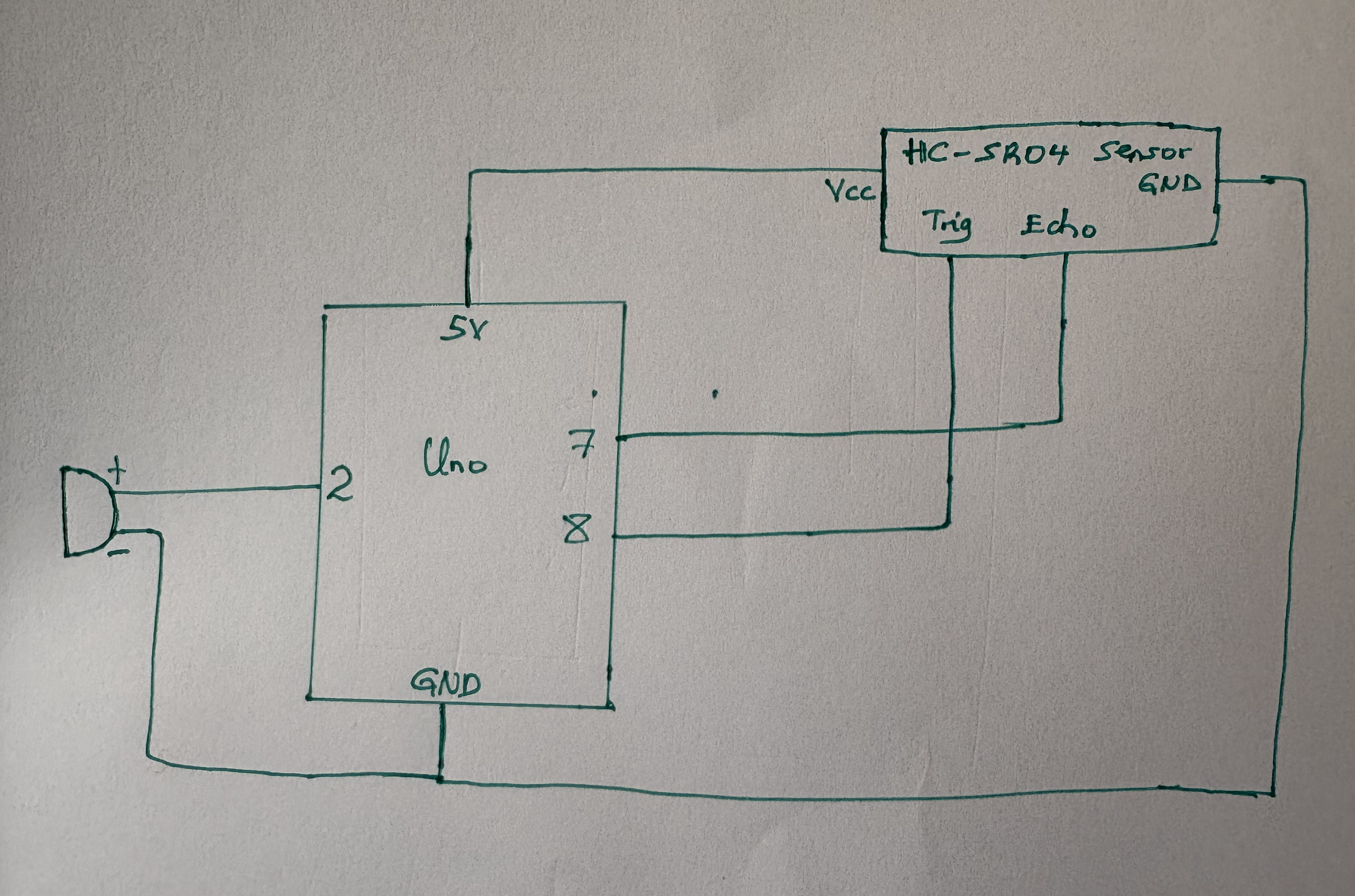
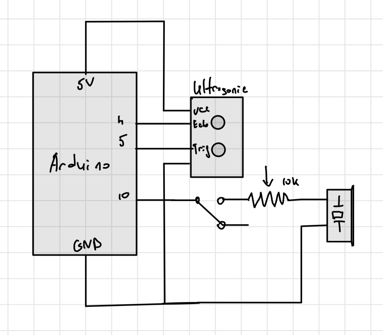
Schematic
Here is the Schematic for our Arduino connections:

Code:
In the implementation of our our idea, we searched for possible combinations of the notes and durations to match the Jingle Bells melody and stored them in an array. We then implemented the code mapping distance with durations. The variations in durations for each note make it seem playing faster or slower. Here is the code:
#include "pitches.h"
#define ARRAY_LENGTH(array) (sizeof(array) / sizeof(array[0]))

// Notes and Durations to match the Jingle Bells
int JingleBells[] =
{
  NOTE_E4, NOTE_E4, NOTE_E4, NOTE_E4, NOTE_E4, NOTE_E4, NOTE_E4, NOTE_G4,
  NOTE_C4, NOTE_D4, NOTE_E4, NOTE_F4, NOTE_F4, NOTE_F4, NOTE_F4, NOTE_F4,
  NOTE_E4, NOTE_E4, NOTE_E4, NOTE_E4, NOTE_E4, NOTE_D4, NOTE_D4, NOTE_E4,
  NOTE_D4, NOTE_G4, NOTE_E4, NOTE_E4, NOTE_E4, NOTE_E4, NOTE_E4, NOTE_E4, NOTE_E4, NOTE_G4,
  NOTE_C4, NOTE_D4, NOTE_E4, NOTE_F4, NOTE_F4, NOTE_F4, NOTE_F4, NOTE_F4,
  NOTE_E4, NOTE_E4, NOTE_E4, NOTE_E4, NOTE_E4, NOTE_D4, NOTE_D4, NOTE_E4,
  NOTE_D4, NOTE_G4,
};

int JingleBellsDurations[] = {
  4, 4, 4, 4, 4, 4, 4, 4,
  4, 4, 4, 4, 4, 4, 4, 4,
  4, 4, 4, 4, 4, 4, 4, 4,
  4, 4, 4, 4, 4, 4, 4, 4, 4, 4,
  4, 4, 4, 4, 4, 4, 4, 4,
  4, 4, 4, 4, 4, 4, 4, 4,
  4, 4
};

const int echoPin = 7;
const int trigPin = 8;;
const int Speaker1 = 2;
const int Speaker2 = 3;
int volume;

void setup()
{
// Initialize serial communication:
  Serial.begin(9600);
  pinMode(echoPin, INPUT);
  pinMode(trigPin, OUTPUT);
  pinMode(Speaker1,OUTPUT);
}

void loop()
{
  long duration,Distance;

// Distance Sensor reading
  digitalWrite(trigPin, LOW);
  delayMicroseconds(2);
  digitalWrite(trigPin, HIGH);
  delayMicroseconds(5);
  digitalWrite(trigPin, LOW);
  duration = pulseIn(echoPin, HIGH);
  Distance = microsecondsToCentimeters(duration);

// Map Distance to volume range (0 to 255)
  volume = map(Distance, 0, 100, 0, 255);
  volume = constrain(volume, 0, 255);

// Play melody with adjusted volume


 playMelody(Speaker1 , JingleBells, JingleBellsDurations, ARRAY_LENGTH(JingleBells), volume);

// Debug output to Serial Monitor
  Serial.print("Distance: ");
  Serial.print(Distance);
  Serial.print("    Volume: ");
  Serial.print(volume);
  Serial.println();
}
// Get Centimeters from microseconds of Sensor
long microsecondsToCentimeters(long microseconds)
{
  return microseconds / 29 / 2;
}
// PlayMelody function to accept volume and adjust note duration
void playMelody(int pin, int notes[], int durations[], int length, int volume)
{
  for (int i = 0; i < length; i++)
  {
// Adjust the note Duration based on the volume
    int noteDuration = (1000 / durations[i]) * (volume / 255.0);

// Play the note with adjusted Durations
    tone(pin, notes[i], noteDuration);
// Delay to separate the notes
    delay(noteDuration * 1.3);
    noTone(pin);
  }
}
Reflection
This week’s assignment was especially interesting because we had a chance to collaborate on the project and combine our imagination and skills to create something original. I really enjoyed working with @Nelson. We worked great as a team by first coming up with an idea and then adjusting the concept to choose the ideal balance between randomness and something ordinary to achieve the final result.
I believe that this project has a lot of potential for future improvements, and perhaps I will use some parts of this week’s assignment for my future ideas and projects. Looking forward to the next weeks of the course!


