Reading Reflection Week 10

A  Brief Rant on the Future of Interaction Design

Bret Victor’s article was both frustrating and inspiring to me. I had not realised how number I’d become to the limitations of  “Pictures Under Glass” which he argues that it is a compromised way to interact with technology. His words made me think of how I have often felt detached from my daily devices like my phone. The smooth, untouchable screens which might seem convenient deny me any real physical feedback making interactions feel shallow.

The article also made me think about what “innovation” really means. To me progress meant having the devices faster and sleeker but now I wonder whether this progress is moving us further from natural, embodied ways of knowing. It leaves me wondering how we can design technology that will genuinely respect and use our physicality. Technology that will feel like extensions of ourself than barriers. Another weird realisation is the fact that the more advanced our devices become, the less they seem to engage with what makes us fundamentally human.

Reading Reflection – Week #10

A Brief Rant on the Future of Interaction Design by Bret Victor

I usually feel very skeptical about videos, such as one that was presented by Microsoft on Productivity Future Vision. But, here are couple of points that I made on it:

  • I really liked how gamification in education was presented in the video, as it feels less daunting to study for children and they feel more integrated in real life.
  • It’s interesting that in all this digitalization, people still have to carry their suitcases physically, they have to wait in lines waiting for train and do other not so productive stuff. So, the video shows a reform in terms of digital devices solely. It’s a shallow vision of the future and our interaction.
  • In the video, I saw future life, which lost its colors, because the main color that you can see are blue, green, white and black. There is no vividness.
  • I didn’t recognize that so many devices convert what we can do to what we want to do.
  • Also, you don’t really think about hands being central point of interaction. Hands our main sensors.
  • Feedback from the objects that we are using usually is not verbal, but we can unconsciously feel things, especially if we remember or extensively use things. For example, I’m using a keyboard with arabic characters for writing in english, kazakh and russian languages, because my hands basically remember the location of each letter, which I’m not really aware of.
  • The Pictures Under Glass concept can be applied to kids games applications, where they play being a hairdresser and cutting someone’s hair.
  • After author of the article said it, I understood that the thing that seemed very strange to me about interactions shown in the video – they felt numb and senseless.
  • I found pictures with hands and objects they carry kind of powerful.
  • It occurred to me that dance as an activity can bring so much understanding about our daily interactions with our body, since we become more conscious about them.
  • I strongly resonated with Bret’s saying that most artistic and engineering projects can’t just be described.
  • I didn’t agree with one of the author’s points that if physical interactions should always be very informative and communicative, since I feel like in today’s interactions there is a lot of imagination employed by the users, hence physical may not be the only priority.
  • I liked that the author addressed comments in separate article, where he also discussed concept of finger blindness, which is really fascinating.

Assignment #7: Moving Closer

Concept & Inspiration.

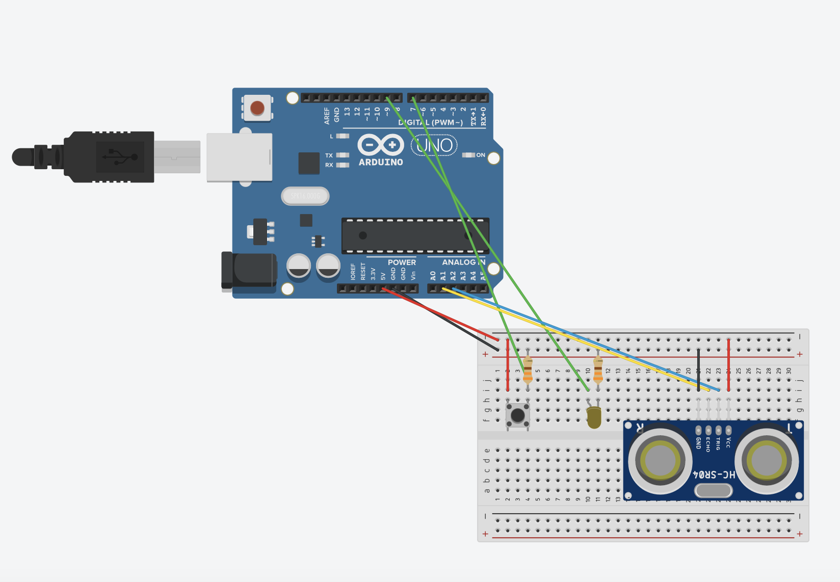
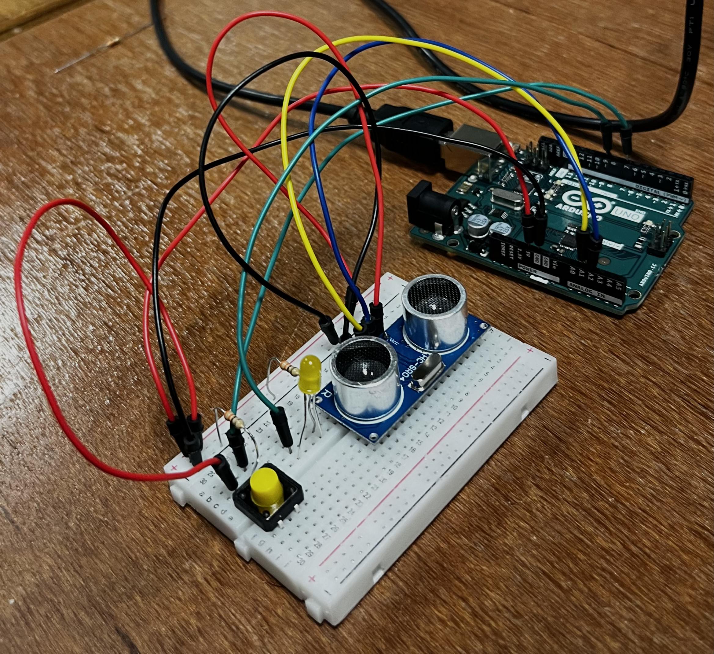
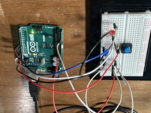
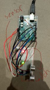
For this project, I decided to practice what has been covered in the class so far but also try to implement a new sensor. My choice fell upon the most bulky of all sensors in our kit – the ultrasonic distance sensor.  By following the tutorial on YouTube, I built my Arduino with a yellow LED light and a button switch.

I got inspiration from final scene of the animated film Inside Out 2, when the emotions gathered together to hug the tree of the Self and “calm down” Riley.

When an object is close to the sensor for at least 10 centimetres, the LED lights up and becomes brighter as the object moves closer. However, when the button is pressed and released, the LED is turned off and it will not react to the object until the button is pressed again.


Highlights.

According to the guidelines of the task, I got information from two sensors – digital (the button switch) and analogue (the ultrasonic sensor). In order to make the button turn on and off, and the LED change the intensity according to the distance from the object, I implemented Boolean functions into my code. I also had to manipulate with delay() function to make the brightness change a bit smoother.

void loop() {
int currentButtonState = digitalRead(buttonPin);

if (currentButtonState == LOW && previousButtonState == HIGH) {
ledState = !ledState; 
delay(50); 
}
previousButtonState = currentButtonState;

digitalWrite(trigPin, LOW);
delay(20);
digitalWrite(trigPin, HIGH);
delay(20);
digitalWrite(trigPin, LOW);

duration = pulseIn(echoPin, HIGH);
distance = duration * 0.034 / 2;

int brightness = 0;

if (ledState) { 
if (distance <= 10) {
brightness = map(distance, 0, 10, 255, 0);
} else {
brightness = 0;
}
} else {
brightness = 0; 
}

analogWrite(ledPin, brightness);
delay(10);
}

Embedded Sketch.

GitHub


Assignment 7 | Close your eyes when the flash is on

Concept

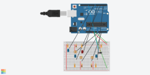
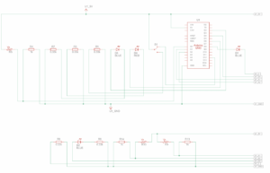
For this assignment, I am imitating the interaction between a camera’s shutter release and the human eye’s reaction to a camera flash. The button represents the shutter release, while the LDR simulates ambient light or flash. The LEDs mimic how the human eye might react to sudden changes in light.

When the button (shutter release) is pressed, it activates the LEDs: the digital LED turns on fully, and the analog LED adjusts its brightness based on the light level detected by the LDR. If the surrounding light level is high, the LED immediately dims, simulating the eye’s reaction to bright flashes.

Implementation

Code

https://github.com/LindaD1234/Intro-To-IM/blob/039cec5b83542a4788a6a4ae24d2adfc22e446ca/Assignment%207

One new thing I discovered is the INPUT_PULLUP, which makes it easy to work with buttons and switches without needing an external resistor.

Reading Reflection – Week #9

Having read Physical Computing’s Greatest Hits (and Misses), I was struck by its relevance and abundance of crucial ideas. As an aspiring interactive media artist, it’s critical for me to understand the balance between creativity and repetition. It’s always a bit intimidating to search for an idea, only to find that it’s been done before. This often leads me to hesitate on projects that feel “too done” and hackneyed. How, then, can one avoid being constrained by the thought that everything has already been made, and still maintain creativity even when an idea isn’t entirely novel?

What’s compelling about this text is that the author offers a fresh perspective: we can harness familiar themes as frameworks for exploration, allowing each iteration to create room for personal interpretation. By illustrating common patterns across various physical computing projects, the author demonstrates that creativity arises not only from the novelty of ideas but also from how people interact with the artwork. The examples provided in the article are very illustrative and somewhat familiar to many of us, as we all encounter similar physical computing models in different forms throughout lives. What sets them apart is, possibly, the way people’s interactions shape each project in unique ways.

This was also the main takeaway from the article Making Interactive Art: Set the Stage, Then Shut Up and Listen, which challenged me to reconsider my approach to interactive art. I often overthink the explanations in my projects, whether they are films or interactive artworks, worrying that the audience might misunderstand or overlook important details. This text was a reminder that such explanations can limit interaction, turning the audience into passive viewers rather than active participants. I strongly agree with the idea that an artwork should invite the audience to “complete” it through their responses, making it less about conveying a single message and more about fostering a dialogue. Transitioning to a mindset where my work is an initial invitation, with the audience’s engagement shaping its evolution, feels both liberating and challenging but essential for impactful interactive art. In this way, recurring themes in my projects become flexible templates rather than restrictive molds, providing me with opportunities for personal expression.

Assignment 7 – Sensor – DJ Set

Concept

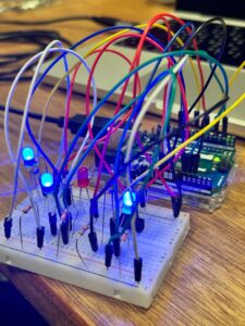
When thinking about concept of my project, I decided to use a light sensor for controlling LEDs in an analogue fashion. I thought initially about making it as an interactive artwork, where the brightness of many LEDs will be controlled by the lighting of the room and the way the users manage light sensors themselves. However that idea didn’t work, because I made a mistake of connecting wires to wrong digital inputs (without PWM~), which led to unsuccessful fading of the LEDs. I realized my mistake too late, and already had switched my idea to something more fun and engaging. As lights were just switching on and off when I covered the light sensor with my finger, it reminded me of DJ Set where you press specific buttons and different sounds occur. I decided to do the same, but replacing sounds with LEDs. I had three LEDs that would be lighted using light sensors. And I also included an LED that was switched on using slide switch, to add digital inputs to the circuit, since light sensors were connected to analog inputs.

Arduino Setup


As you can see, I just followed the rhythm of the song with my DJ Set.

Highlight of the code

GitHub Link

int sensorValue = analogRead (A0);
Serial.println (sensorValue);
sensorValue = constrain (sensorValue, 10,200);
brightness = map (sensorValue, 15, 140, 0, 255);
analogWrite (ledPin2, brightness);
delay (10);

int sensorValue2 = analogRead (A1);
sensorValue2 = constrain (sensorValue2, 10,200);
brightness1 = map (sensorValue2, 15, 140, 0, 255);
analogWrite (ledPin3, brightness1);
delay (10);

int sensorValue3 = analogRead (A2);
sensorValue3 = constrain (sensorValue3, 10,200);
brightness2 = map (sensorValue3, 15, 140, 0, 255);
analogWrite (ledPin4, brightness2);
delay (10);

I think the hardest part of the coding was just with assigning correct numbers and pins to each function. I decided to use “constrain” and “map” functions that we learned on our lesson, because when building my project in IM Lab I found the light sensor values on Serial Monitor vary only from 15 to 140, hence I mapped them to 255 range, so that brightness could be manipulated. As it can be seen from the Arduino setup and the video, there are a lot of wires on the breadboard, which was another challenge of connecting them just right and not fail the code.

Reflection

In my next improvements of the project, I wish to experiment with different types of sensors, such as temperature, ultrasonic and sound sensors. It would give my project higher difficulty and also interest. Also, I am very eager to learn and employ Piezo Speaker in my next projects, as a further development of the DJ set. Moreover, it would make sense if I would use bigger breadboard and make connections more clear, reducing unnecessary  wires. I would also want to connect RGB LED, as it gives higher flexibility and room for experimentation.


Assignment 6 – Fluttering Pulse

For this pr0ject, the task was to get information from at least one analog sensor and at least one digital sensor (switch), and use this information to control at least two LEDs, one in a digital fashion and the other in an analog fashion, in some creative way.

Inspiration

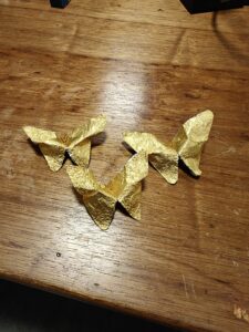
My project was inspired by a few of my favorite things. Firstly, I’ve always loved butterflies and origami, and I often find myself folding little origami butterflies from random bits of paper I find lying around. Adding on to that, my all time favorite chocolate is Ferrero Rocher, and sometimes, after enjoying one, I fold the shiny gold wrapper into a butterfly. They look beautiful, with the gold and shimmer giving them an extra touch.

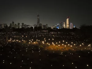
I wanted this project to feel personal, so I thought, why not bring these gold butterflies to life? It’s a fun “best out of waste” idea that lets me reuse something in a creative way. I was also inspired by the 2023 Abu Dhabi art installation Pulse Island by Rafael Lozano-Hemmer. It basically consists of an array of over 4,000 Edison lightbulbs that illuminate the plant life of Lulu Island. Each lightbulb glimmers to the rhythm of the heartbeat of a different participant. The way this piece interacts with people’s heartbeats was fascinating and sparked the idea of making something that reacts to simple sensor inputs.
Concept

For this project, I created three butterflies from Ferrero Rocher wrappers. I placed a yellow LED on each butterfly, intending to bring them to life in a way that responds to a person’s heartbeat. Using a pulse sensor, the setup detects the person’s heart rate, sending analog input to the LEDs. This means the yellow lights on each butterfly will pulse in sync with the person’s heartbeat, with the intensity of the lights varying based on the heart rate’s intensity (BPM value). Also, a blue LED is used to indicate when the setup is active, turning on and off with a button that acts as a digital switch. When the button is pressed, the blue LED lights up, showing that the butterflies are ready to respond to the heartbeat input.

The overall blinking effect of the LEDs  gives each butterfly a sense of “life,” as if they are fluttering gently in time with the person’s pulse.

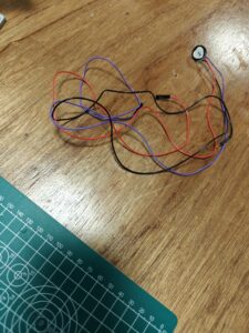
Here’s what the butterflies and pulse sensor looked like:


Implementation

For this project, I used an Arduino UNO board, a pulse sensor, three yellow LEDs (connected in parallel), one blue LED, one push button, two 330-ohm resistors, and one 10K-ohm resistor. The setup is designed to illuminate the yellow LEDs in sync with a person’s heartbeat and control the blue LED as an indicator of the system’s state.

The push button acts as a digital input, turning the setup on or off. When the button is pressed, the blue LED is activated (handled through digitalWrite) to indicate that the system is running. Meanwhile, the pulse sensor detects the user’s heart rate, sending the analog data to control the brightness of the yellow LEDs. The brightness/intensity is mapped to the person’s beats per minute (BPM). Also, the yellow LEDs pulse in sync with the heart rate (they glow every time a heartbeat is detected), creating a visual heartbeat effect. The code initializes and configures the pulse sensor to read the heartbeat, and then it uses a map function to translate the BPM into a suitable brightness level for the LEDs.  The analogWrite function is used to control the intensity of the yellow LEDs based on the BPM.

For the pulse sensor, I used the PulseSensorPlayground library, which simplifies the integration of heart rate monitoring by providing functions to read and interpret heartbeat data easily.

I also created a custom delay function to avoid the blocking nature of the regular delay() function. Normally, delay() pauses all processes in the Arduino, which would prevent the button presses from being detected during the delay period. My custom delay function allows for non-blocking delays, so the button state can still be read while waiting.

GitHub URL

Here’s some of the code (which controls the mapping of pulse rate to LED brightness and makes the LEDs beat in sync with the person’s heartbeat) that I am proud of:

// Checks if the setup is active
  if (flag == true){ 
    digitalWrite(digitalLED, HIGH); // Turns on the blue LED to indicate active state
    if (pulseSensor.sawStartOfBeat()) {            // Constantly test to see if "a beat happened".
      int myBPM = pulseSensor.getBeatsPerMinute();  // Calls function on our pulseSensor object that returns BPM as an "int".
                                                    // "myBPM" hold this BPM value now. 
      Serial.println("♥  A HeartBeat Happened ! "); // If test is "true", print a message "a heartbeat happened".
      Serial.print("BPM: ");                        // Print phrase "BPM: " 
      Serial.println(myBPM);                        // Print the value inside of myBPM. 
      int val = map(myBPM, 0, 180,0, 255);          // Maps the BPM value to an LED brightness level
      Serial.print("val:");
      Serial.println(val);                          // Prints the mapped brightness value
      analogWrite(LED, val);                        // Sets the brightness of the yellow LED based on the BPM
      myDelay(100);                                 // Waits for 100 milliseconds
      analogWrite(LED, 0);                          // Turns off the yellow LED to create a pulsing effect
    }
  }

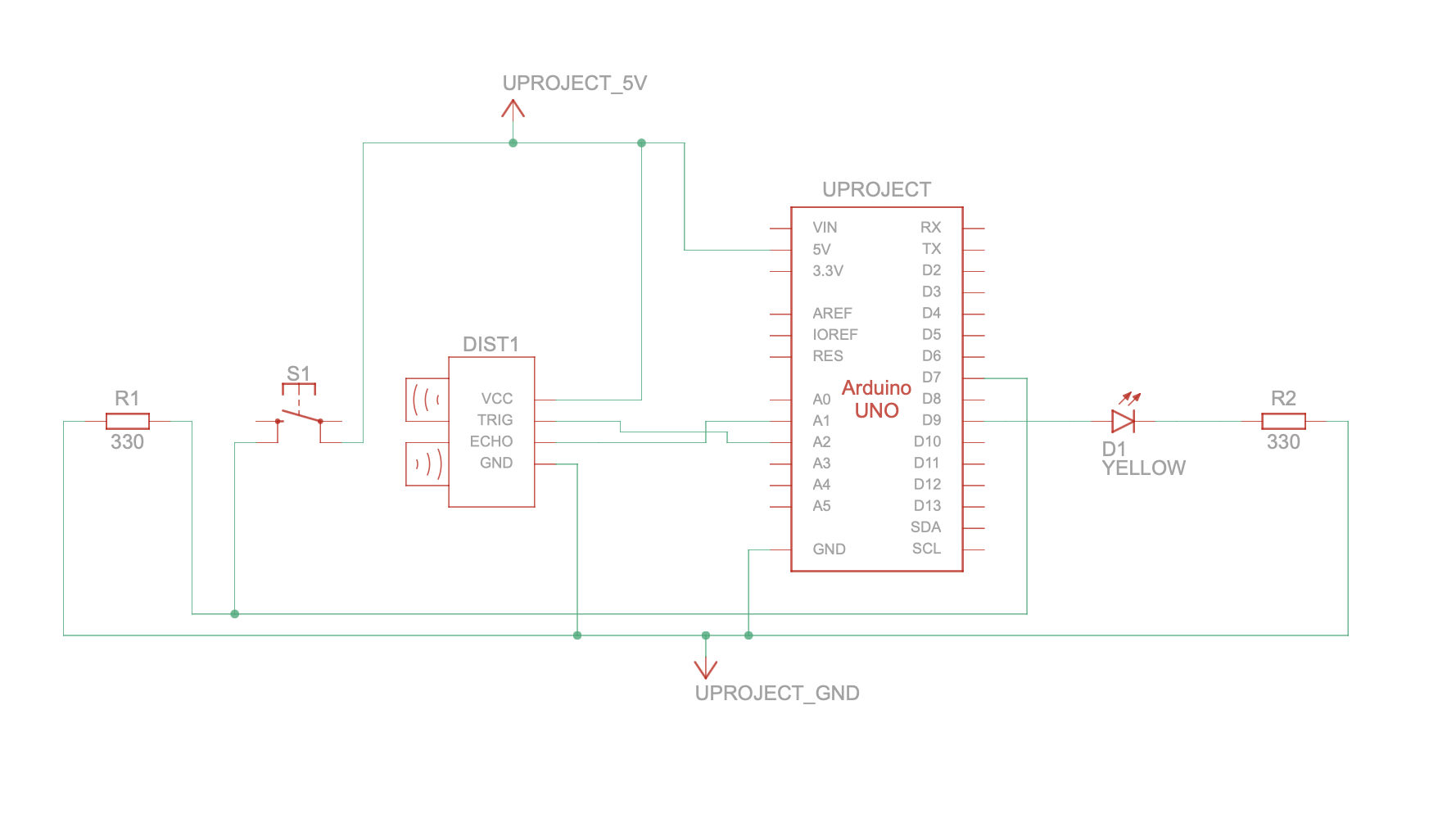
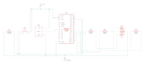
Schematic Circuit Diagram

Reflections and Further Improvements

I’m really happy with how this project turned out and how the concept came to life. It was really rewarding to incorporate elements that are personally meaningful to me, like the origami butterflies, and also to successfully learn how to use a new type of sensor.

In the future, I’d love to add sound to enhance the interactive aspect, maybe syncing gentle tones with the heartbeat to make the experience more immersive. I’d also like to expand the setup visually, adding more butterflies and refining the aesthetics to make the project even more captivating.

Resources

Pulse Island

PulseSensorPlayGround

Temperature Sensor

Concept

Using both digital and analog switches, I came up with a scheme that allows to change the colour and intensity of the RGB LED depending on the state of the button and values captured by the temperature sensor.

When the button is pressed, the RGB LED turns off, otherwise it is on – this is an example of working with digital switch, which works with high-low states. When the temperature sensor captures a value higher than 25C, the RGB LED lights up with red, and the light becomes more intense the higher the temperature increases. When the sensor captures a value lower than 25C, the RGB lights up with blue, and the light becomes more intense the lower the temperature decreases – this is an example of working with an analog switch, which allows to manipulate a spectrum of values.

Highlight of the code

It took me a long time to come up with the baseline temperature that would make the switch from red to blue light in room temperature conditions possible. In the end, I could use my own hands to make the sensor feel warmth, and then I used a frozen thermos wrapped in tissues to make the value decrease below 25 degrees.

if (switchState == LOW) {

  if (temperature > baselineTemp) {
   
    int redBrightness = map(temperature, baselineTemp, 30, 0, 255);
    redBrightness = constrain(redBrightness, 0, 0);
    analogWrite(redPin, redBrightness);
    analogWrite(greenPin, 0);
    analogWrite(bluePin, 0);
  } 
  
  else {
    
    int blueBrightness = map(temperature, baselineTemp, 25, 0, 255);
    blueBrightness = constrain(blueBrightness, 0, 0);
    analogWrite(redPin, 0);
    analogWrite(greenPin, 0);
    analogWrite(bluePin, blueBrightness);
  }
}


Demonstration

Amina_Temperature

Reflection

For future improvements of this idea, I could play with more shades of RGB LED light that would be associated with different values on the spectrum, since this electrical component allows to work with almost any colour of the light.

WEEK 9 – traffic light

CONCEPT:

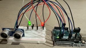
For my project, I’ll be creating a traffic light system. I got the idea for this project while driving, and I thought it would be interesting to implement this concept in my work by creating a sensor that reacts like a traffic light. My goal is to create a system that changes based on a car’s distance from the light, just like real traffic signals. I’ll use an ultrasonic sensor to detect the car’s proximity and control two LEDs: one red and one green.

In my code, I’ll program the red LED to start dim and gradually get brighter as the car gets closer, signaling the car to slow down and stop. When the car reaches a specific point, I’ll use a switch in the code to light up the green LED, showing that it’s safe for the car to proceed. This setup uses the sensor data to adjust the brightness of the red LED, while the switch allows for an easy transition to the green light, creating a basic but effective interactive traffic light system.

SETUP:

VIDEO DEMONSTARTION:

IMG_1442

HIGHLIGHT:

The part of my code I was really proud of was when I filled out the mapping and measuring distance while setting the LED brightness and figuring out a way to debug the code as it kept getting corrupted. This code snippet measures distance using an ultrasonic sensor and adjusts an LED’s brightness based on how close an object is. First, ‘pulseIn(echoPin, HIGH);’ measures the time for a sound wave to travel to an object and return, which I convert to centimeters using ‘int distance = duration * 0.034 / 2;’. I then map this distance to an LED brightness range (0-255): ‘int brightness = map(distance, 0, 100, 255, 0);’, making the LED brighter as the object gets closer. I use ‘Constrain()’ to keep the brightness within the allowed range. Finally, ‘analogWrite sets the LED brightness based on distance, and’ Serial.print() outputs the values in the serial monitor for easy debugging. This part of the code was a struggle as it was something new; however, with a couple of tries, i got it

// Measure the time it takes for the echo to return
long duration = pulseIn(echoPin, HIGH);

// Calculate the distance in centimeters
int distance = duration * 0.034 / 2; // Speed of sound is ~0.034 cm/us

// Map the distance to LED brightness
int brightness = map(distance, 0, 100, 255, 0); // Closer = brighter, max distance = dim
brightness = constrain(brightness, 0, 255);     // Keep brightness within 0-255

// Set the brightness of the distance LED
analogWrite(distanceLedPin, brightness);

// Print switch state, distance, and brightness to the Serial Monitor for debugging
Serial.print("Distance: ");
Serial.print(distance);
Serial.print(" cm, LED Brightness: ");
Serial.println(brightness);

CODE:

arduino file

REFLECTION:

For future improvements, I would like to add a yellow LED to create a full traffic light sequence, transitioning smoothly from red to green, with a yellow warning light in between. I also noticed that the brightness adjustment could be more gradual, so tuning the mapping range would improve the overall responsiveness.

RESOURCES:

https://projecthub.arduino.cc/Isaac100/getting-started-with-the-hc-sr04-ultrasonic-sensor-7cabe1


Reading Reflection – Week #9

Physical Computing’s Greatest Hits (and misses)

As I was scrolling through the article by Tigoe before reading it, I immediately recognised several works I have read about or saw before. As I started reading it in depth, I understood why – these categories of physical computing projects are indeed very popular. Nonetheless, some of them were still unexpected, for example, I have never thought that a popular Dance Revolution arcade game is in fact an example of physical computing. This illustrates how many systems we interact with actually belong to one or several of the outlined types of projects, but we tend to overlook this. I plan to experiment with these categories further, possibly creating something on the edge of several ideas.

Making Interactive Art: Set the Stage, Then Shut Up and Listen

Coming from Visual Arts background, I am used to providing a description for each of my works, explaining what was the idea behind the piece and sometimes how to look at it. After reading the article by Tigoe, my perception on the explanatory part had been changed – I have not thought about the importance of open interpretation for interactive works before. From perspective of the creator, I often feel that I have to define the ways audience should observe my art, otherwise they might overlook something. As a viewer, I do feel that sometimes installations and other immersive works in museums and galleries can seem too predefined. As the author mentions, the basics should be outlined and the rest of the job should be left for the interactor – and I agree with this balance.