Concept
When we first started working with the Arduino, I was intrigued by learning about how certain sensors work. Last year, I used an Ultrasonic Sensor for an experiment for my physics class, and once I discovered a similar but less advanced sensor in our Sparkfun kit, I was eager to understand how it functions. Additionally, since the assignment required us to use LED, I came up with an interesting idea. Similar to how a park-assist sensor works to determine the distance between the car’s bumper and a wall, I decided to use the sensor to determine how close an object is and consequently alternate the brightness of an LED based on how far away the object is. Since we hadn’t learned about the HC-SR04 distance sensor, I looked through Sparkfun’s guide, where every element of our kit was explained. There, I found a good example of how the sensor functions.
Implementation
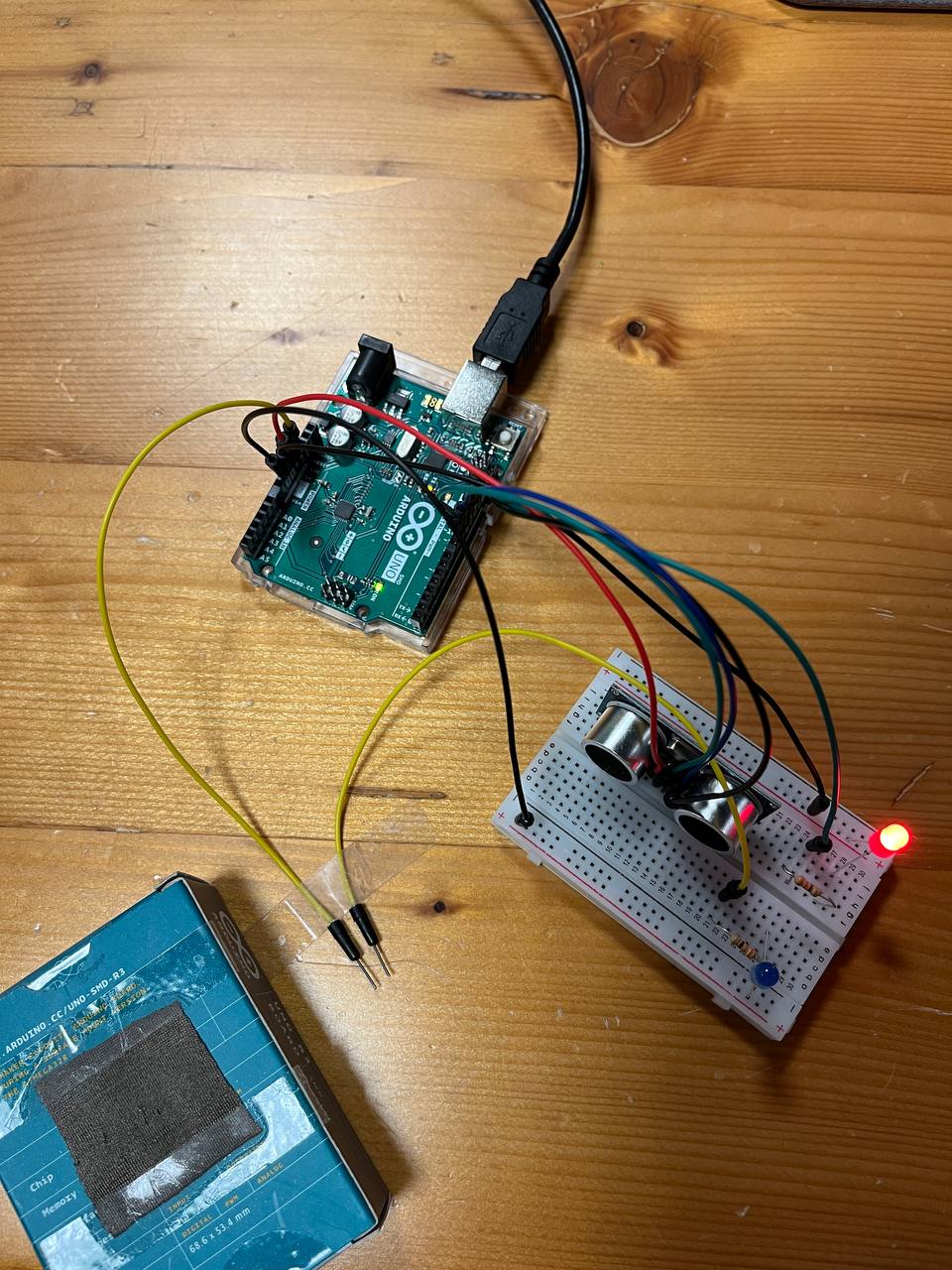
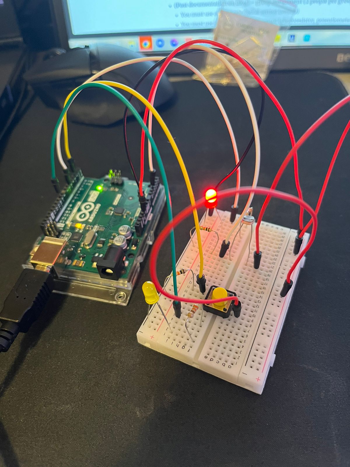
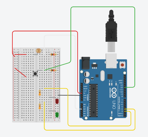
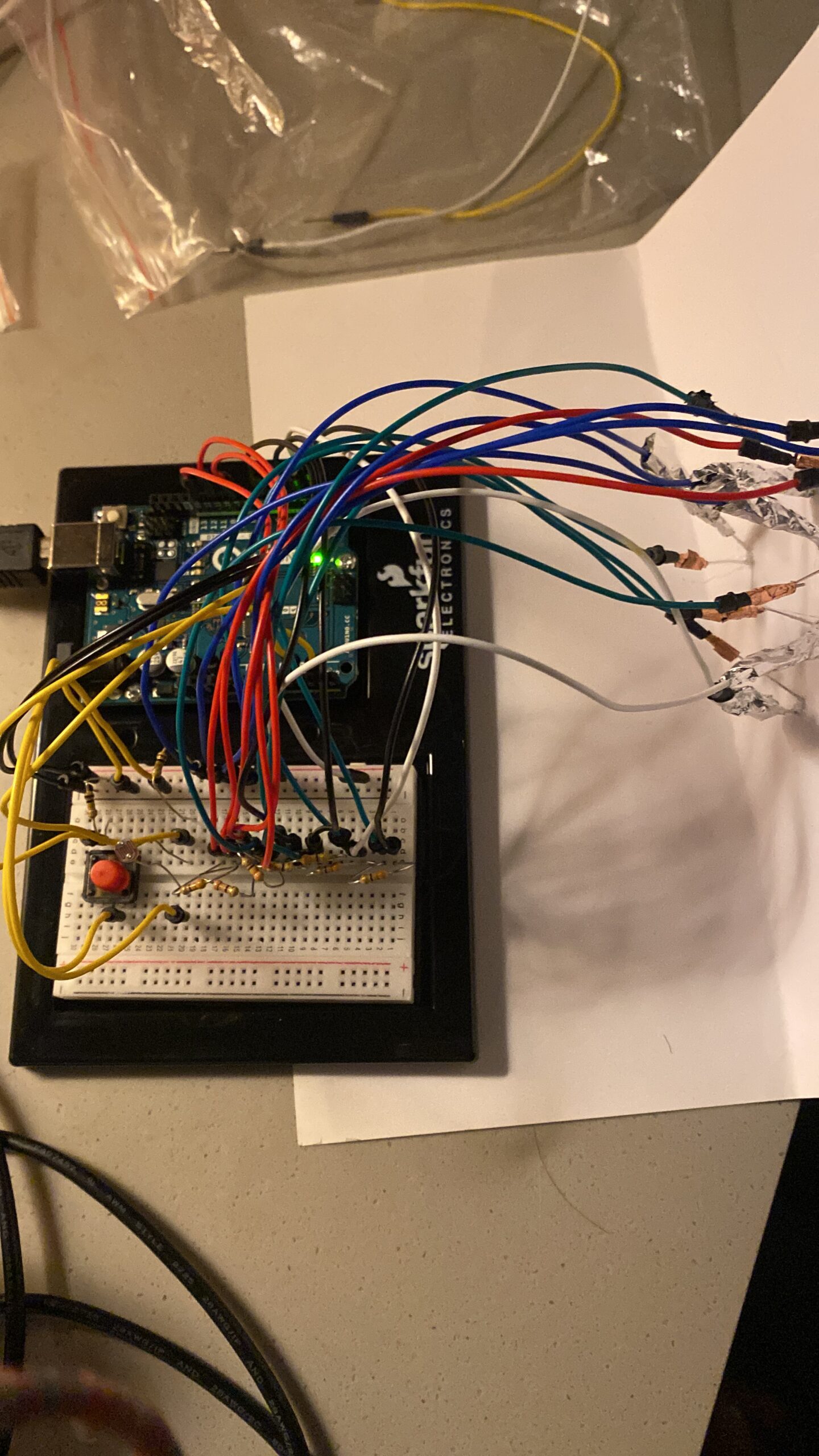
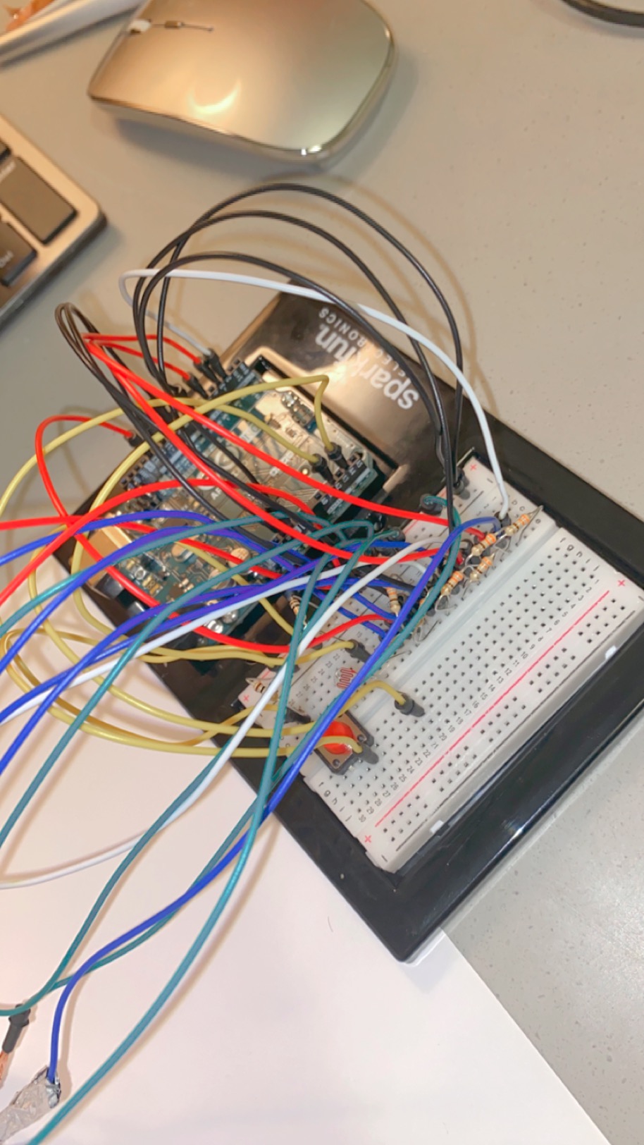
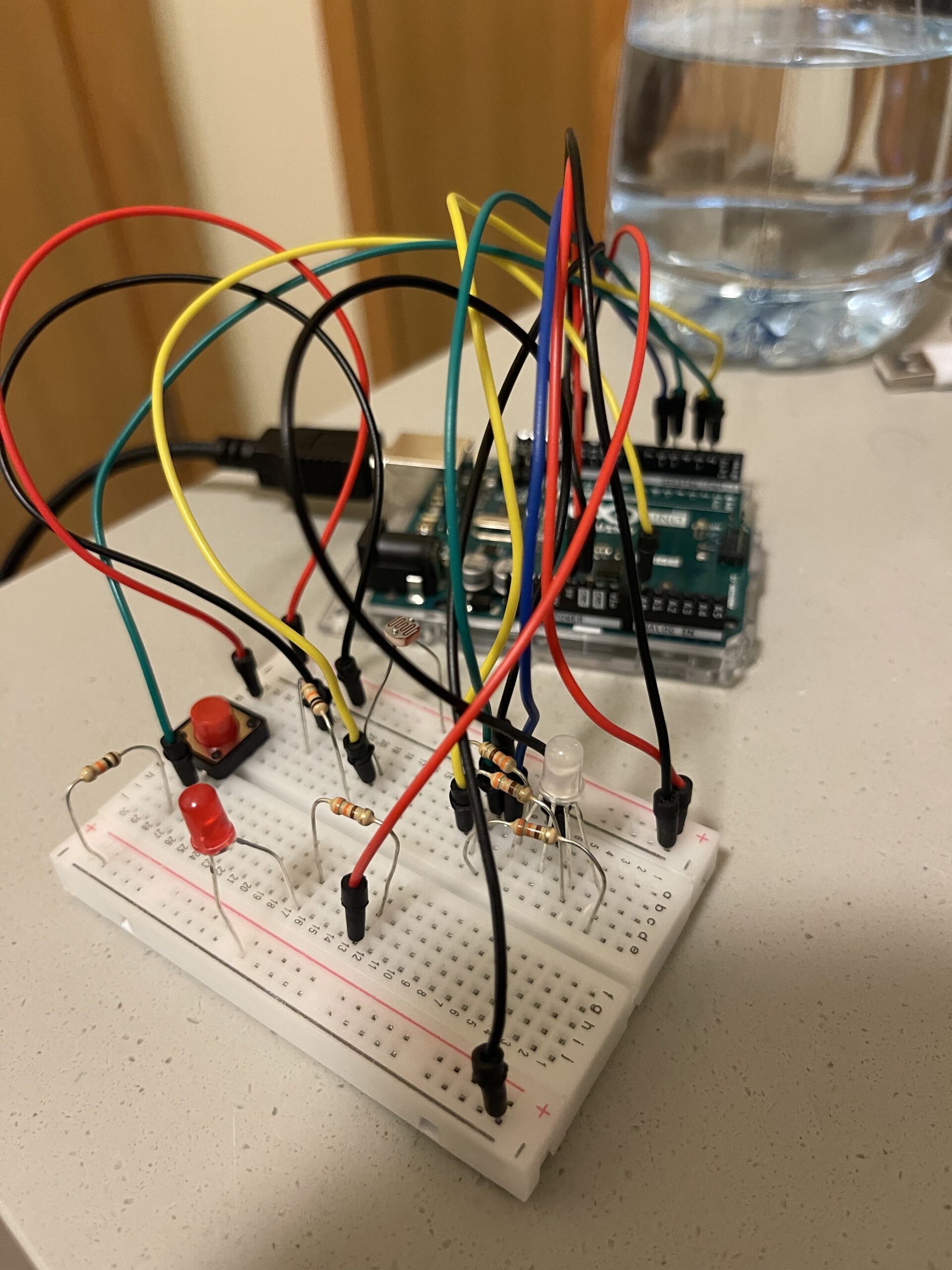
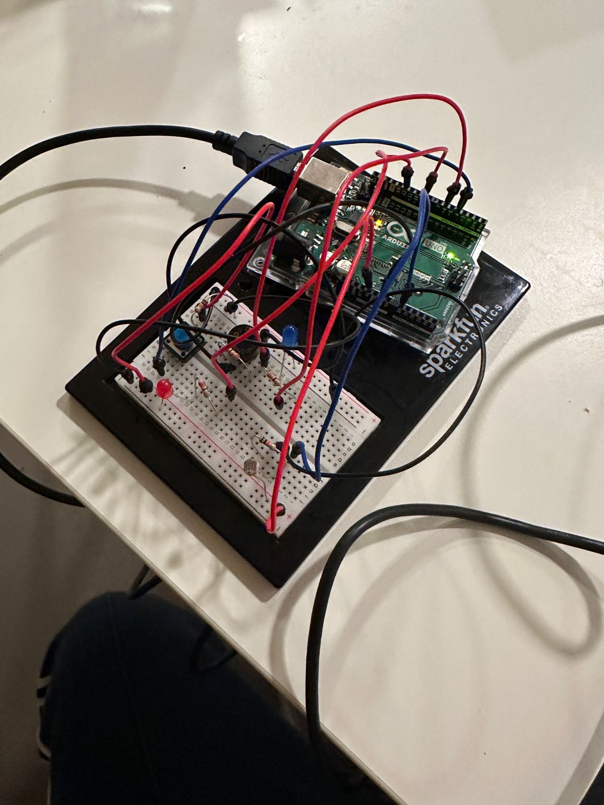
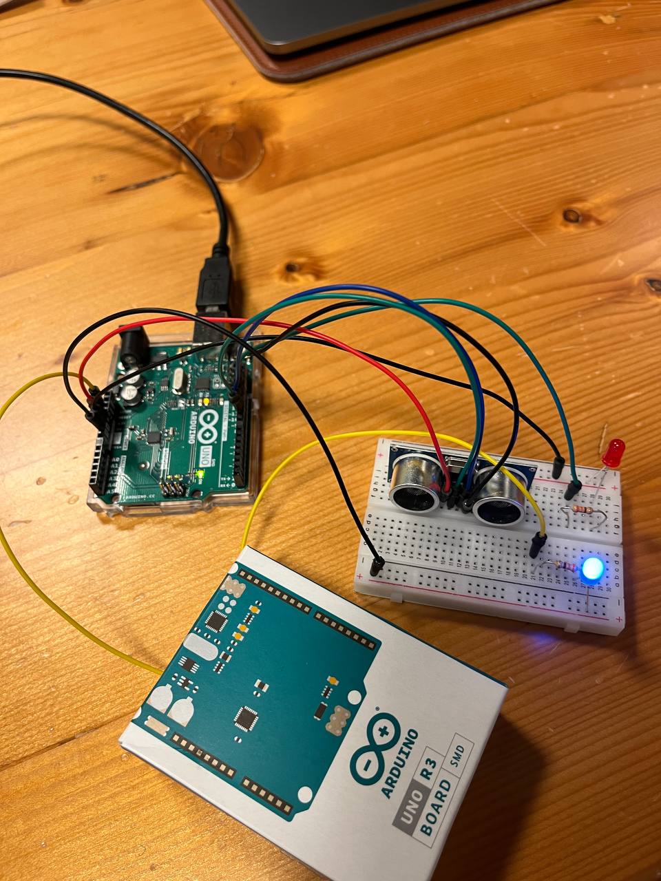
Initially, the process seemed quite simple: connect the sensor to the breadboard, use the jumper wires to connect it to the Arduino, and use the information gathered by the sensor to manipulate an LED connected to a PWM pin, which would allow me to use analogWrite. However, as I quickly discovered, it is vital to be precise in every component of the circuit. Accidentally, I managed to overload one of the LEDs I was using, consequently burning it. I am still unsure where the issue was; however, I suspect it could’ve been the cathode of the LED which was very close to the resistor. If it had accidentally touched the starting part of the resistor, the current would jump straight into the LED before it went through the resistor and thus burnt the LED. Nevertheless, apart from this minor issue, everything else worked well and after tinkering around with the code, I was able to produce exactly what I had envisioned. One of the two LEDs was multipurpose. It can be turned on using the button (digital switch) and controlled in a digital fashion. Additionally, that same LED circuit is also connected to a different pin, which allows it to turn on once the distance sensor value exceeds a certain threshold. One other issue I encountered was with converting the data from the analog sensor into understandable units. The example provided by Sparkfun used inches as their units; however, I decided to use a ruler and experiment with the math to adjust the sensor to be accurate using centimeters. Two videos of the working project and the code are below:
const int ECHO_PIN = 12;       //input, collects data from waves
const int TRIG_PIN = 11;       //output, sends out the waves

const int RED_LED = 8;         // red to light up when objects close
const int YELLOW_LED = 6;      // yellow to fade if object getting further

float distance = 0;            // variable to store distance

void setup() {
  Serial.begin (9600);         // set up a serial connection with the computer

  pinMode(ECHO_PIN, INPUT);    // echo pin measure the duration of pulses coming back from the distance sensor
  pinMode(TRIG_PIN, OUTPUT);   // trigger pin output pulses of electricity

  //set LED pins to output
  pinMode(RED_LED, OUTPUT);
  pinMode(YELLOW_LED, OUTPUT);
  pinMode(PUSH_BUTTON, INPUT_PULLUP);
}

void loop() {
  distance = getDistance();   //variable to store distance measured by the sensor in cm

  Serial.print(distance);     //print the distance that was measured
  Serial.println(" cm");      //print units after the distance

// if conditional to control LED's depending on distance.
  if (5 <= distance && distance <= 30) {
    int brightness = map(distance, 5, 30, 255, 0);
    analogWrite(YELLOW_LED, brightness);
    digitalWrite(RED_LED, LOW);
    Serial.println(brightness);
  } else if (distance < 5) {
    digitalWrite(RED_LED, HIGH);
  } else {
    analogWrite(YELLOW_LED, 0);
    digitalWrite(RED_LED, LOW);
  }
}

float getDistance() {
  float echoTime;                   //variable to store the time it takes for a ping to bounce off an object
  float calculatedDistance;         //variable to store the distance calculated from the echo time

  //send out an ultrasonic pulse that's 10ms long
  digitalWrite(TRIG_PIN, HIGH);
  delayMicroseconds(10);
  digitalWrite(TRIG_PIN, LOW);

  echoTime = pulseIn(ECHO_PIN, HIGH);      //pulsein command to see how long it takes for pulse to bounce back to sensor

  calculatedDistance = echoTime / 55.2;    //calculate  distance of object that reflected the pulse in cm

  return calculatedDistance;               //send back calculated distance
}
Reflection
Overall, I found this experience to be extremely useful and crucial in understanding how to find information about new sensors and objects I could use for future projects, as well as understanding how to structure the code for the collection of sensor data. I also found it extremely helpful to print out the values of the sensor to help me adjust the math calculations, which is common practice I used in P5JS to determine if everything was working well, and it translates well into the physical computing environment.


 .
.